 Ir al contenido

- Metal insert molding bonds a pre-formed metal component inside plastic during injection for a permanent, load-bearing assembly.
- Mechanical retention from knurls, grooves, and undercuts dominates the bond strength; adhesive contribution is secondary.
- Brass is the most common insert material because it machines easily, resists corrosion, and handles thread-forming loads.
- Insert shift, sink marks, and poor bonding are the top three defects—each preventable through gate placement, wall thickness, and surface preparation.
- This process beats ultrasonic welding and press-fitting when you need high torque resistance and hermetic sealing in one cycle.
What Is Metal Insert Injection Molding?
La moldura por inyección de insertos metálicos se define por la función, las restricciones y los compromisos explicados en esta sección. Si está comparando proveedores o planificando la procuración, nuestra guía de selección de proveedores de moldura por inyección cubre la preparación de RFQ, la cualificación y las verificaciones de riesgo comercial.
dispara un segundo material plástico sobre un primer sustrato plástico. El moldeo por inserción implica específicamente colocar un componente prefabricado—casi siempre metálico, a veces cerámico u otra pieza premoldeada—en la cavidad antes de que comience el ciclo. La inserción metálica normalmente se carga manualmente, mediante un brazo robótico o a través de un alimentador vibratorio automatizado en forma de tazón. moldeo por inyección es un proceso de fabricación que coloca un componente metálico preformado en la cavidad del molde antes de inyectar plástico fundido a su alrededor. El resultado es un ensamblaje único y permanentemente unido que combina la conductividad, la resistencia de las roscas y la rigidez del metal con la libertad de diseño y el bajo peso del plástico.
The distinction from sobremoldeo1 importa. El sobremoldeo dispara un segundo material plástico sobre un primer sustrato plástico. moldeo por inserción2 específicamente implica colocar un componente prefabricado—casi siempre metálico, en ocasiones cerámico o otra pieza pre-moldeada—en la cavidad antes de que comience el ciclo. El inserto metálico normalmente se carga manualmente, mediante un brazo robótico o mediante un alimentador vibratorio automatizado. Una vez que el inserto está correctamente posicionado, el molde se cierra y el plástico fundido fluye alrededor, encajando el componente metálico en la geometría final de la pieza. Este proceso de una sola etapa elimina pasos de ensamblaje secundarios como prensado, soldadura ultrasónica o adhesión, lo cual reduce tanto el costo como el riesgo de fallos.

En nuestra fábrica de Shanghai, operamos 47 máquinas de moldeo por inyección desde 90T hasta 1850T, lo que nos da la flexibilidad para manejar trabajos de moldeo por inserción desde delicadas inserciones electrónicas M1.0 hasta bujes automotrices de servicio pesado.
“Insert-molded threads can withstand 5–10× more assembly cycles than self-tapping screws in plastic bosses.”Verdadero
Self-tapping screws cut threads into plastic during each insertion, progressively degrading the boss material. Insert-molded brass threads distribute load across full metal thread engagement, maintaining clamping force across hundreds of assembly cycles without strip-out.
“Insert molding cycle times are always much longer than standard injection molding cycles.”Falso
With automated insert loading, the added time is often only 3–5 seconds per cycle. The injection, packing, and cooling phases are nearly identical to standard molding. On high-volume automotive connector jobs, cycle times of 18–22 seconds including insert placement are achievable.
How Does the Metal Insert Molding Process Work?
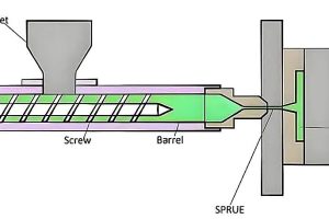
En proceso de moldeo por inyección3 for insert molding follows the same fundamental cycle as standard molding, but with a critical pre-step: loading the metal component into the cavity. Here is the complete sequence, broken down step by step.
Step 1: Insert Preparation
Before any plastic flows, the metal inserts must be clean, dry, and free of machining oils or surface contaminants. Many shops run inserts through an ultrasonic cleaning bath or a solvent dip followed by hot-air drying. Contaminants on the insert surface act as release agents, destroying the mechanical bond between metal and plastic.
Some applications call for preheating the inserts to 80–120 °C. Preheating reduces the temperature differential between the molten plastic and the cold metal, which minimizes residual stress at the interface and prevents premature freeze-off that would otherwise create a weak bond line. Preheating is especially important with high-shrink materials like nylon and polypropylene.
Step 2: Insert Placement
The mold opens, and the insert is placed into its designated location in the cavity side of the mold. For low-volume production, operators load inserts by hand using tweezers or vacuum wands. For high-volume runs, robotic arms or automated feed systems (vibratory bowl feeders, escapement mechanisms) place inserts with positional accuracy of ±0.05 mm or better.
En diseño de moldes Debe incluir características de retención positiva—pines con resorte, bolsillos magnéticos o soportes cónicos—que mantengan la inserción en posición durante el cierre del molde y la inyección. Sin retención, el flujo de material fundido a alta presión (normalmente 50–150 MPa) desplazará la inserción, resultando en piezas defectuosas.
Step 3: Mold Closing, Injection, and Packing
Once the insert is seated, the mold closes and the injection unit fills the cavity with molten plastic at temperatures ranging from 200 °C (for polypropylene) to 380 °C (for PEEK). The melt flows around the insert, conforming to every surface feature. Packing pressure holds the plastic against the cavity and insert surfaces as the material cools and shrinks.
Packing pressure and time are more critical in insert molding than in standard molding. The plastic must remain under pressure long enough to compensate for volumetric shrinkage around the insert. Insufficient packing causes sink marks on the outer surface opposite the insert and voids at the metal-plastic interface.
Step 4: Cooling and Ejection
Cooling accounts for 60–70% of the total cycle time. The mold’s cooling channels must extract heat from both the plastic and the metal insert, which acts as a thermal mass. In some designs, the insert’s thermal conductivity works in your favor—brass inserts, for example, help cool the surrounding plastic faster.
After cooling, the mold opens and the finished part is ejected. Ejector pins must be positioned to avoid contact with the insert itself, which could damage surface features or push the insert partially out. For delicate parts, air-blow ejection or robotic extraction is preferred.
Which Materials Work Best for Metal Insert Molding?
Material selection in insert molding involves two independent decisions: the metal insert material and the plastic substrate. The interface between them—the bond line—depends on the interaction of both.
Metal Insert Materials
Brass (C36000 or C37700) dominates insert molding for one reason: it is the best all-around compromise. It machines easily into complex knurled and threaded shapes, resists corrosion without plating, conducts heat well (which helps during molding), and costs significantly less than stainless steel. For threaded inserts, brass handles repeated assembly torque without galling or thread deformation.
Stainless steel inserts (303, 304, or 316 grades) appear in medical devices, food-contact applications, and corrosive environments where brass would fail. The trade-off is higher material cost, harder machining (which increases insert price by 2–3×), and lower thermal conductivity, which extends cooling time.
El moldeo por inserción introduce defectos que el moldeo por inyección estándar nunca ve. Estos son los cuatro problemas más frecuentes y sus causas raíz.
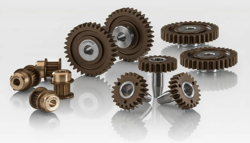
Plastic Substrate Selection
The plastic must be chosen for both the application requirements and its compatibility with the insert molding process. High-shrink-rate materials like polypropylene (PP) and nylon (PA6, PA66) create strong compressive grip on inserts as they cool—but they also generate higher residual stress at the interface. If the wall section around the insert is too thin, this stress can cause cracking.
Engineering thermoplastics like polycarbonate (PC), PBT, and PPS are popular insert molding substrates because they offer lower shrinkage (0.4–0.7% vs. 1.5–2.5% for PP), better dimensional stability, and higher operating temperatures. PEEK is used in aerospace and medical applications where the finished part must survive autoclave sterilization or continuous temperatures above 250 °C.
Glass-filled grades (PA66-GF30, PBT-GF30) are common in structural applications because the glass fiber reduces shrinkage and increases stiffness around the insert. However, glass-filled materials are more abrasive to the mold and may require hardened steel cavities.
Interface Bond Mechanism
The bond between metal and plastic in insert molding is almost entirely mechanical. Unlike overmolding, where chemical compatibility between two plastics can create a molecular bond, metal and thermoplastic do not form covalent bonds. The retention comes from three sources: shrink-fit compression from plastic cooling, mechanical interlocking with surface features (knurls, grooves, undercuts), and friction from the normal force exerted by the compressed plastic.
“Mold flow simulation before cutting steel can prevent 90% of insert-shift and weld-line problems.”Verdadero
Simulation predicts how the melt front will interact with the insert, showing pressure differentials that cause shift and identifying weld line positions before the mold is built. Correcting gate location or insert position in software costs a fraction of modifying a finished mold.
“Adhesive bonding between metal and plastic provides the primary retention force in insert molding.”Falso
The bond in insert molding is overwhelmingly mechanical. Shrink-fit compression, knurl interlock, and groove engagement account for 95%+ of retention. Adhesive bonding contributes negligibly because thermoplastic melts do not form covalent bonds with metal surfaces.
| Material | Coste | Thread Life | Resistencia a la corrosión | Conductividad térmica |
|---|---|---|---|---|
| Brass (C36000) | Bajo | Excelente | Bien | High (120 W/m·K) |
| Stainless Steel (303/304) | Medio-Alto | Bien | Excelente | Low (16 W/m·K) |
| Aluminum (6061) | Medio | Feria | Feria | Very High (167 W/m·K) |
| Copper (C11000) | Medio | Feria | Feria | Highest (390 W/m·K) |
| Steel (1018) | Bajo | Bien | Poor (needs plating) | Medium (50 W/m·K) |
What Are the Critical Mold Design Considerations?
Las consideraciones críticas de diseño de moldes son las principales categorías u opciones explicadas en esta sección. El diseño del molde para moldeo con insertos requiere más atención que un molde estándar porque no solo se gestiona el flujo de plástico, sino también el posicionamiento preciso de un componente metálico rígido dentro de un entorno de alta presión y alta temperatura.
Insert Positioning and Retention
The cavity must include features that locate the insert with repeatability better than ±0.05 mm. Common approaches include tapered seats (which self-center the insert), spring-loaded retaining pins (which grip the insert and release during ejection), and magnetic pockets (for ferromagnetic inserts). The choice depends on insert geometry, production volume, and whether loading is manual or automated.
For multi-cavity molds, each cavity must have identical insert retention features. Even small differences in insert seating depth between cavities create inconsistent bond strength and part dimensions. Mold maintenance schedules should include regular measurement of insert seat dimensions.
Gate Placement and Melt Flow
Gate location determines how the melt front approaches and flows around the insert. The gate should direct flow so that the melt wraps symmetrically around the insert, filling both sides at approximately the same rate. Asymmetric filling creates unbalanced pressure on the insert, causing it to shift during injection.
Avoid placing the gate directly opposite the insert. The high-velocity melt jet hitting the insert surface can cause two problems: it can push the insert out of position, and it can create a flow line or weld line on the far side where the split melt stream reunites. A tangential or edge gate that directs flow along one side of the insert is usually more reliable.
Cooling Channel Layout
The metal insert acts as a heat sink during cooling, which can be either helpful or problematic depending on the design. Brass inserts cool the surrounding plastic quickly, but they also create uneven cooling if the cooling channels are not balanced around the insert. Uneven cooling causes warpage and differential shrinkage.
Vent Placement
Trapped air around insert features (knurls, undercuts) creates burn marks and weak bond lines. Vents must be ground at the parting line and near any dead-end flow paths created by the insert geometry. Vent depth should be 0.01–0.02 mm—deep enough to let air escape, shallow enough to prevent flash.
What Design Guidelines Ensure Reliable Insert-Molded Parts?
Good insert-molded parts start at the DFM stage. The following guidelines come from production experience across thousands of insert-molded part designs.
Wall Thickness Around Inserts
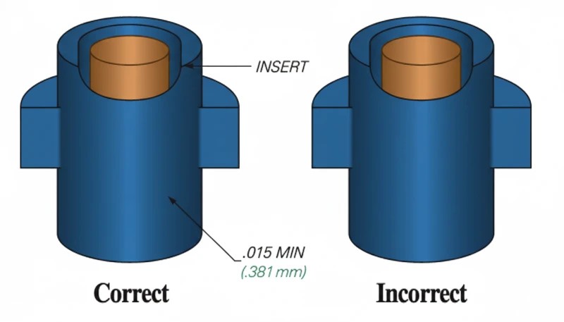
Maintain a minimum wall thickness of 1.5× the insert diameter between the insert outer surface and the part exterior. For a 6 mm diameter insert, that means at least 9 mm of outer diameter on the plastic boss. Going thinner risks sink marks on the outer surface and cracking from shrinkage stress. Going thicker wastes material and extends cooling time.
The wall should be uniform around the insert. Variable wall thickness creates uneven shrinkage, which pulls the insert off-center. If the design requires a non-circular boss shape, use a constant thickness between the insert and the outer wall rather than a constant outer profile.
Insert Shape and Surface Features
Knurling is the most common surface treatment for round inserts. Diamond knurling provides good axial and rotational retention. Straight knurling resists pull-out but not rotation. For maximum retention in both directions, use a combination of diamond knurling and one or more circumferential grooves.
Undercuts on the insert (such as a T-head or flanged profile) provide the strongest retention because the plastic physically cannot pull past the undercut without failing. However, undercuts complicate both insert manufacturing and mold ejection—use them only when the application demands maximum pull-out strength.
Anti-Rotation and Anti-Pullout Design
For threaded inserts, anti-rotation is critical. The insert must not spin inside the plastic when a screw is driven or removed. Two design strategies work: hexagonal or square insert bodies that key into the plastic, and knurled surfaces that create mechanical interlock. Combining both is the most reliable approach for high-torque applications.
Anti-pullout design focuses on maximizing the shear area at the insert-plastic interface. Longer engagement length, wider grooves, and larger diameter flanges all increase pull-out force. A typical well-designed M3 brass insert in PA66-GF30 should achieve 500–800 N of pull-out force and 0.5–1.0 N·m of torque resistance.
Tolerance Stack-Up
Insert molding introduces an additional tolerance variable: the insert’s position relative to the mold cavity. The final positional accuracy of the insert in the finished part depends on the mold seat tolerance, the insert manufacturing tolerance, and the plastic shrinkage. Budget ±0.1–0.2 mm for insert positional accuracy in a well-designed, well-maintained mold.
What Are the Most Common Defects and How Do You Prevent Them?
Los defectos más comunes y cómo prevenirlos son las categorías principales o opciones explicadas en esta sección. El moldeo por inserción introduce defectos que el moldeo por inyección estándar nunca ve. Aquí están los cuatro problemas más frecuentes y sus causas principales.
Químico + Mecánico
Insert shift occurs when the melt flow pushes the metal component out of its intended position. The result is an off-center insert, uneven wall thickness, and potentially exposed metal on one side. Root causes include asymmetric gate placement, excessive injection speed, insufficient insert retention in the mold, and unbalanced multi-cavity flow.
Solutions: Use mold flow simulation to verify balanced fill around every insert. Reduce injection speed in the first stage to lower the dynamic pressure on the insert. Improve mold retention features—switch from gravity seats to spring-loaded pins or tapered interference fits. In multi-cavity tools, balance the runner system so all cavities fill at the same rate.
Sink Marks and Voids
Sink marks appear on the part surface opposite a thick insert because the large thermal mass cools slowly, and the plastic shrinks away from the cavity wall. Voids form internally when the outer skin freezes before the core has fully packed out.
Solutions: Increase packing pressure and extend packing time to compensate for volumetric shrinkage around the insert. Preheat inserts to reduce the temperature gradient. Maintain minimum wall thickness of 1.5× insert diameter. Consider using a foaming agent (microcellular molding) for very thick boss sections.
Poor Bond Strength
When pull-out force falls below specification, the usual culprits are surface contamination on the insert, insufficient packing pressure, and premature freeze-off. Oil, grease, or mold release agent on the insert surface prevents the plastic from conforming to the knurl or groove profile.
Solutions: Implement a cleaning protocol (ultrasonic bath or solvent wash) for all incoming inserts. Increase melt temperature by 10–20 °C to improve flow into surface features. Extend packing time. If using regrind material, limit the regrind percentage to 15% or less, as degraded material has poor flow characteristics.
Part Warpage and Cracking
Differential shrinkage between the insert area (constrained by metal) and the free-shrinking plastic walls causes warpage. In extreme cases, the residual stress around the insert exceeds the plastic’s tensile strength, causing radial cracks in the boss wall.
Solutions: Use a lower-shrink material or a glass-filled grade. Preheat the insert to reduce the temperature shock. Design the boss with uniform wall thickness and add gusset ribs for structural support. Annealing the finished part at a temperature below the plastic’s heat deflection temperature can relieve residual stress without deforming the part.
How Do You Test and Validate Insert-Molded Assemblies?
Quality validation for insert-molded parts goes beyond standard dimensional inspection. The metal-plastic interface requires dedicated mechanical testing to verify that the bond meets application requirements.
Pull-Out Testing
A universal testing machine grips the plastic part and applies axial force to extract the insert. The test measures peak pull-out force and records the failure mode—whether the plastic fractures, the insert pulls free from the knurl, or the plastic boss ruptures. A well-designed M3 brass insert in glass-filled nylon should consistently achieve 500–800 N pull-out force.
Pull-out testing should be performed on samples from each cavity at the start of production, then periodically during the run. A 10–15% drop in pull-out force from initial samples signals a process drift—typically increasing mold temperature, degrading material, or worn insert seats.
Torque Testing
For threaded inserts, a calibrated torque wrench drives a screw into the insert until either the specified installation torque is reached or the insert spins inside the plastic. The torque-to-failure value defines the maximum safe working torque—typically set at 50–60% of the failure torque for production specifications.
Torque testing catches problems that pull-out testing misses. An insert may have excellent axial retention from deep knurling but poor rotational resistance if the knurl pattern is too fine or the plastic did not fully pack into the grooves.
Cross-Section Analysis
Sectioning an insert-molded part and examining the cut face under magnification reveals the quality of the bond interface. Look for voids between the insert and plastic, incomplete fill of knurl grooves, and sink marks on the outer surface. Cross-section analysis is destructive and typically performed during initial process qualification and after any tool modifications.
Environmental and Life-Cycle Testing
Thermal cycling (typically -40 °C to +85 °C or higher, depending on the application) tests whether differential expansion between metal and plastic causes bond degradation over time. Thermal shock testing with rapid temperature transitions is especially aggressive—it exposes any weak bond line within 50–100 cycles.
Humidity exposure matters for hygroscopic materials like nylon. After 48 hours at 85% RH and 85 °C, nylon absorbs enough moisture to swell 0.5–1.0%, which can reduce the compressive grip on the insert by 15–25%. Always test under realistic end-use conditions.
Where Is Metal Insert Molding Used Across Industries?
Metal insert molding serves any industry that needs strong, reliable metal-to-plastic bonds. The four largest application sectors are automotive, electronics, medical devices, and consumer products.
In automotive, insert-molded threaded inserts appear in interior trim panels, instrument cluster housings, sensor bodies, and under-hood electrical connectors. A single mid-size car contains 50–100 insert-molded threaded bosses. Automotive suppliers specify pull-out and torque values for every insert, and production parts must pass statistical process control sampling to maintain PPAP documentation.
Electronics applications include PCB mounting bosses, RF shield retention posts, battery terminal blocks, and connector housings.
The trend toward miniaturization has driven demand for inserts as small as M1.0, which require precision molds with 0.01 mm tolerance insert seats and specialized loading automation.
Medical device manufacturers use insert molding for instrument handles, surgical tool components, and diagnostic equipment housings. Stainless steel inserts are standard in this sector because they survive autoclave sterilization and meet biocompatibility requirements. ISO 13485 quality systems require full traceability of every insert lot to the finished device.
Consumer products—power tool housings, kitchen appliances, sporting equipment, and toys—use insert molding for threaded assembly points that must survive repeated disassembly and reassembly. The cost premium of a brass insert (typically $0.02–$0.10 each in volume) is trivial compared to the warranty cost of a stripped plastic thread.
Beyond these four sectors, insert molding appears in telecommunications hardware (fiber optic connector ferrules, base station antenna brackets), industrial equipment (valve bodies, actuator housings, sensor mounts), and defense applications where threaded metal-to-plastic joints must withstand shock and vibration loads specified by MIL-STD standards. Emerging EV battery applications use insert-molded stainless steel mounting bosses for structural attachment and electrical grounding.
Engineers evaluating joining methods often compare insert molding against three alternatives. Each has distinct strengths and limitations.
Insert Molding vs. Overmolding
Insert molding encapsulates a rigid, pre-made component (usually metal) in plastic. Overmolding molds a second plastic material over a first plastic substrate, creating a soft-touch grip, a seal, or a multi-color part. Overmolding can create a chemical bond between the two plastics if they are compatible (for example, TPE over PP). Insert molding relies entirely on mechanical retention. Choose insert molding when you need metal properties; choose overmolding when you need multi-material plastic integration.
Outsert molding is the inverse of insert molding—it injects plastic features onto a flat metal substrate rather than placing metal inside plastic. Ultrasonic insertion drives a metal insert into a pre-molded plastic boss using high-frequency vibration as a secondary operation. Both avoid insert molding’s tool complexity but sacrifice bond consistency and strength.
The key trade-off: insert molding produces stronger, more consistent bonds because the plastic packs uniformly around the insert under controlled pressure and temperature. Ultrasonic insertion creates a bond that depends on vibration amplitude, insertion depth, and plastic melt during a brief 0.5–2 second cycle—more variables, more opportunity for inconsistency.
Frequently Asked Questions About Metal Insert Injection Molding
¿Cuál es el espesor mínimo de pared alrededor de un inserto metálico en el moldeo por inyección?
El punto de inicio habitual es al menos 1.5 veces el diámetro de la inserción como pared plástica alrededor de la inserción metálica, con más margen para resinas frágiles o con carga de vidrio. La pared también debe mantenerse uniforme alrededor del refuerzo. Si un lado es delgado y el opuesto es grueso, la contracción por refrigeración se vuelve desigual y aumenta el riesgo de fractura. Para roscas que soportan carga, confirme la pared con pruebas de extracción y torque, en lugar de depender solo de un valor de manual durante la toma de muestras. Confirme la elección con datos de muestras de producción.
¿Puedes usar insertos de aluminio en lugar de latón en el moldeo por inserción?
Sí, pero el aluminio no es un reemplazo directo del bronce en cada pieza moldeada por inserción. El aluminio reduce peso y mejora la transferencia de calor, pero es más blando, más fácil de deformar durante la carga, y generalmente ofrece menor durabilidad de rosca. Use it para carcasas livianas, dispositivos portátiles o piezas aeroespaciales donde la masa importa. Para ensamblaje repetido con tornillos, bronce o acero inoxidable es generalmente más seguro, excepto que pruebas prueben que la inserción de aluminio cumple la especificación de torque y extracción bajo carga real y temperatura. Confirme la elección con datos de muestras de producción.
¿Qué tan precisa es la posicionamiento de la inserción en piezas moldeadas por inserción?
El posicionamiento de inserción en producción típica puede mantener aproximadamente más o menos 0.05 a 0.10 mm cuando el molde tiene soportes positivos para la inserción, carga estable y control de cierre. Una precisión más estrecha es posible, pero depende de la tolerancia de la inserción, la repetibilidad del cargador, la presión del material fundido y el equilibrio de la cavidad. No juzgue la precisión solo desde CAD. Valídelo con verificaciones CMM de primera pieza y repita las verificaciones en cada cavidad, porque un localizador débil puede crear desviación que solo aparece después que la herramienta se calienta. Confirme la elección con datos de muestras de producción.
¿Funciona el moldeo por inserción con plásticos de alta temperatura como el PEEK?
Sí, el moldeo por inserción puede funcionar con plásticos de alta temperatura como PEEK, PPS, PEI y nylon de alta temperatura, pero el diseño de la inserción y del molde debe manejar temperaturas de procesamiento mucho más altas. La inserción metálica puede requerir precalentamiento para que el material fundido no se solidifique demasiado rápido alrededor del estriado o la ranura. El proveedor también necesita acero para herramientas, sistema de distribución de material caliente y controles de secado adecuados para la resina. Para piezas críticas, realice una prueba específica del material antes de comprometerse con la herramienta de producción y las dimensiones finales. Confirme la elección con datos de muestras de producción.
¿Qué causa que las piezas moldeadas por inserción se agrieten alrededor del refuerzo?
La fractura alrededor del refuerzo generalmente proviene de tensión residual, grosor desigual de pared, esquinas afiladas cerca de la inserción, o una gran diferencia de temperatura entre la inserción fría y el material plástico fundido caliente. Los materiales de alta contracción agravan el problema porque el plástico quiere contraerse mientras la inserción metálica restringe el movimiento. Las soluciones normales son grosor uniforme de pared, radios generosos, resina con carga de vidrio o de menor contracción, precalentamiento de la inserción, y validación con ciclos térmicos, no solo inspección a temperatura ambiente antes del envío y aprobación. Confirme la elección con datos de muestras de producción.
¿Cuántas inserciones se pueden moldear en una sola pieza?
Una pieza puede contener un inserto o muchos insertos, pero el límite práctico lo establecen la precisión de carga, el tiempo de ciclo, el acceso a la cavidad y el riesgo de hardware mal cargado. La carga manual suele ser mejor para cantidades bajas o piezas simples con uno a tres insertos. La carga robótica se vuelve más atractiva cuando aumenta el número de insertos, la orientación debe ser repetible o la fatiga del trabajador genera errores. Cada inserto añadido debe tener un asiento positivo y una característica clara de poka-yoke en el diseño del molde. Confirme la elección con datos de muestreo de producción.
¿Es el moldeo por inserción adecuado para la producción de bajo volumen?
El moldeo por inserción puede ser adecuado para producción de bajo volumen cuando la pieza necesita fuerza confiable, integración sellada metal-plástico, o posicionamiento repetible que la inserción secundaria no puede entregar. Puede no ser económico para refuerzos roscados simples por debajo de unos cientos de piezas, porque el molde requiere soportes para la inserción y trabajo extra de muestreo. Para prototipos o corridas de transición, compare tres rutas: moldeo por inserción manual, inserción ultrasónica después del moldeo, y mecanizado más ensamblaje. Elija basándose en el riesgo total, no solo en el costo de la herramienta para el comprador. Confirme la elección con datos de muestras de producción.
-
overmolding: Overmolding is a two-shot injection molding process where a second plastic material is molded over a first substrate to create a multi-material or multi-color part. ↩
-
insert molding: Insert molding is a manufacturing process in which a pre-formed component is placed into an injection mold cavity and encapsulated by molten plastic to form a single integrated assembly. ↩
-
injection molding process: The injection molding process is a cyclic manufacturing method in which plastic pellets are melted, injected under pressure into a mold cavity, cooled, and ejected as a solid part. ↩


 EN
EN  ES
ES  FR
FR  DE
DE  PT
PT  AR
AR  RU
RU  JA
JA  KO
KO  IT
IT  NL
NL  TR
TR  PL
PL 