Ihre Produktion läuft wie geschmiert. Dann, bei Zyklus 60.000, schickt ein Kunde ein Foto von Gratbildung an Ihrem Teil – die Art, die um 2 Uhr morgens seine Montagevorrichtung blockiert. Sie gehen die letzten drei Monate durch und stellen fest: Niemand hat nach Zyklus 50.000 in dieses Werkzeug geschaut.
Werkzeuginspektion ist die systematische Untersuchung eines Spritzgießwerkzeugs, um Verschleiß, Verunreinigungen, Maßabweichungen und Schäden zu erkennen, bevor sie Ausschuss produzieren oder eine Produktionslinie stoppen. Richtig durchgeführt ist sie die Maßnahme mit der höchsten Kapitalrendite im Werkzeugmanagement. Schlecht gemacht – oder ausgelassen – verwandelt sie einen Reinigungstermin für $200 in eine Notfallreparatur für $20.000.
- Die Formeninspektion erkennt Verschleiß und Verunreinigungen, bevor sie Ausschuss oder ungeplanten Stillstand verursachen.
- Ein strukturierter Inspektionsplan – ausgelöst durch Schusszahl, nicht durch Kalender – ist zuverlässiger als intervallbasierte Pläne.
- Die Trennfläche, Entlüftungen und Auswerferstifte sind die drei am stärksten verschleißenden Bereiche in jedem Serienwerkzeug.
- Eine vorbeugende Inspektion alle 50.000 Zyklen kostet nur einen Bruchteil eines ungeplanten Produktionsstillstands.
- Die Kombination aus visuellen Kontrollen, Maßnahmen zur Dimensionsmessung und Funktionsprüfungen liefert das vollständigste Bild des Werkzeugzustands.
Was ist eine Werkzeuginspektion?
Eine Forminspektion ist eine strukturierte Prüfung aller Funktionsbereiche einer Spritzgießform — Kavitätsoberflächen, Trennebene1, Entlüftungen, Verteilerkanäle, Auswerfersystem, Kühlkanäle und Schließelemente —, um Verschleiß zu messen, Verunreinigungen zu erkennen und die Maßhaltigkeit gegenüber den ursprünglichen Spezifikationen zu bestätigen.
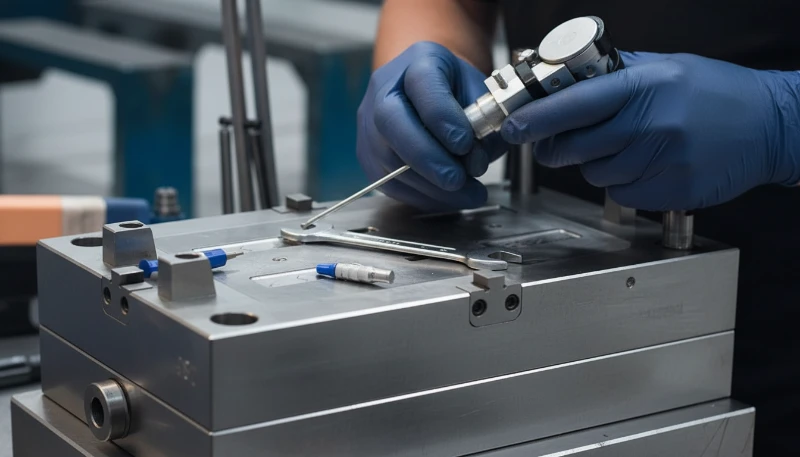
Es handelt sich nicht um einen oberflächlichen Sichtcheck. Eine ordnungsgemäße Inspektion verwendet eine definierte Checkliste, kalibrierte Messwerkzeuge (Messuhren, Luftmessgeräte, Endoskope für Kühlkanäle) und dokumentierte Ergebnisse, die mit den Basiswerten aus der Erstqualifizierung der Form verglichen werden. Das Ergebnis ist kein Pass/Fail-Stempel – es ist eine priorisierte Aktionsliste: jetzt reinigen, diese überwachen, vor dem nächsten Lauf ersetzen.
Der Unterschied zwischen Inspektion und Wartung ist wichtig. Inspektion ist diagnostisch: Sie ermitteln den aktuellen Zustand des Werkzeugs. Wartung ist korrigierend: Sie handeln aufgrund der Inspektionsergebnisse. Die Inspektion auszulassen und direkt zur geplanten Reinigung überzugehen, ist wie das Ölwechseln Ihres Autos nach festem Zeitplan, ohne die Motorkontrollleuchte zu prüfen – Sie reinigen vielleicht ein einwandfreies Werkzeug und ignorieren gleichzeitig einen gebrochenen Auswerferstift.
Warum die Formeninspektion wichtiger ist, als die meisten Teams denken
Gratbildung tritt in weniger als 3.000 Schüssen auf, sobald eine Trennlinie über 0,05mm abgenutzt ist – und beschleunigt sich dann. Wenn ein Qualitätsprüfer den Grat bei der Endkontrolle entdeckt, hat das Werkzeug typischerweise bereits 5.000–10.000 fehlerhafte Schüsse produziert. Das ist kein Defektproblem; es ist ein Inspektionslückenproblem.

Das eigentliche Kostenargument für die Inspektion lässt sich auf drei Kategorien reduzieren. Erstens, Ausschuss und Nacharbeit: Eine Form, die bei einem 16-fach-Werkzeug mit 1.000 Schüssen pro Stunde 2% Grat erzeugt, verschwendet 320 Teile pro Stunde. Bei 0,50 €/Teil sind das 160 €/Stunde an Ausschuss – 3.840 € in einer 24-Stunden-Schicht. Zweitens, Notfallreparatur: Ungeplante Formausbau erfordert beschledigte Bearbeitung, oft zum 2–3-fachen des Standardsatzes, plus Kosten für Linienstillstand. Drittens, reduzierte Werkzeuglebensdauer: Verunreinigungen in den Kühlkanälen erhöhen die Formtemperatur, beschleunigen die Stahlermüdung und können die Formlebensdauer um 30–40% verkürzen.
Eine Inspektion kostet dagegen Zeit und einen Techniker. Bei einem mittelgroßen Serienwerkzeug dauert eine gründliche Inspektion nach 50.000 Zyklen 4–8 Stunden plus Materialkosten. Die Rechnung ist einfach: Selbst eine verhinderte Stillstandszeit rechtfertigt ein ganzes Jahr mit geplanten Inspektionen.
Bei ZetarMold führen wir für Produktionswerkzeuge eine verpflichtende Formeninspektion alle 50.000 Schüsse durch. Werkzeuge, die geplante Inspektionen auslassen, entwickeln 3-mal schneller Grat – eine vorbeugende Reinigung bei 50.000 Schüssen kostet weniger als 1% eines ungeplanten Produktionsstillstands, der die Montagelinie eines Kunden lahmlegt.
Die sechs Zonen, die jede Formeninspektion abdecken muss
Sechs Bereiche sind für 90%+ aller Werkzeugausfälle verantwortlich; eine gründliche Inspektion deckt sie alle systematisch ab.
Zone 1 – Trennlinie und Formfläche: Die Trennlinie ist der primäre Verschleißpunkt jeder Form. Prüfen Sie auf Oberflächenschäden, Metallverformungen und Spalte, die zu Gratbildung führen könnten. Verwenden Sie eine Fühllehre entlang des gesamten Umfangs; jede Messung über 0,03 mm bei einer Präzisionsform ist ein Warnsignal. Untersuchen Sie die Formfläche auf Narben, Rost oder Ablagerungen durch Plastikabbau.
Zone 2 – Kavitäten- und Kernoberflächen: Untersuchen Sie die Kavitätenoberflächen mit hellem Licht und Lupe. Suchen Sie nach Kratzern, Erosion nahe den Angüssen, Ablagerungen von abgebautem Material und jeglichen Veränderungen der Oberflächenbeschaffenheit, die sich auf das Teil übertragen würden. Vergleichen Sie die Oberflächenrauheit mit dem ursprünglichen Finishprotokoll, falls vorhanden. Bei optischen oder Class-A Teilen ist jede sichtbare Markierung auf der Kavität ein Fehler, der zu Ausschuss führt.
Zone 3 – Entlüftung: Entlüftungen verstopfen mit jedem Schusszyklus, da sich flüchtige Stoffe aus dem Kunststoff auf der Entlüftungsfläche ablagern. Eine blockierte Entlüftung erhöht den Kavitätendruck, verbrennt den Kunststoff am letzten Füllpunkt und kann mit der Zeit den Stahl rissig machen. Entlüftungstiefe und -flächenbreite sollten mit der Spezifikation verglichen werden – typische Entlüftungstiefen liegen bei 0,015–0,025 mm für amorphe Harze und 0,025–0,038 mm für teilkristalline.
| Bereich | Wichtige Prüfung | Werkzeug | Eingreifschwelle |
|---|---|---|---|
| Trennungslinie | Spalt / Ebenheit | Fühlerlehre | > 0.03mm → kennzeichnen |
| Kavität / Kern | Oberflächenzustand | 10× Lupe, LED-Licht | Jede Anriss- oder Kratzerbildung → dokumentieren |
| Entlüftung | Entlüftungstiefe und Sauberkeit | Tiefenmessschraube | Verstopft oder außerhalb der Toleranz → reinigen |
| Auswerfersystem | Stiftdurchmesser, Bindung | Stiftlehre, manueller Hub | Festsitzend oder untermaßig → austauschen |
| Kühlungskanäle | Skalierung, Durchflussrate | Boreskop, Durchflussmesser | 15% Durchflussabfall → Entkalken |
| Läufer / Anguss | Erosionsmessung | Tiefenmessschraube | > 0.1mm Erosion → Einsatz ersetzen |
Zone 4 — Auswerfersystem: Prüfen Sie jeden Auswerferstift auf Grate, Verbiegungen und Schwergängigkeit. Ein einziger festsitzender Stift kann das Bauteil reißen lassen, die Oberfläche beschädigen oder dazu führen, dass das Werkzeug unter Schließdruck offen hängen bleibt. Prüfen Sie die Rückholfedern auf Ermüdung und stellen Sie sicher, dass sich die Auswerferplatte über ihren gesamten Hub frei bewegt. Wenn das Werkzeug mehr als 500,000 Schuss absolviert hat, sollten die Auswerferstiftbohrungen auf Rundheit gemessen werden.
Zone 5 — Kühlsystem: Die Kühlkanalprüfung ist der am häufigsten übersehene und zugleich einflussreichste Bereich. Bereits 0.25mm Ablagerung senken die Wärmeübertragungseffizienz um 40%. Prüfen Sie Kanalwände mit einem Endoskop; messen Sie die Wassertemperaturdifferenz zwischen Ein- und Auslass (Ziel: im Werkzeug innerhalb 3°C). Der Durchfluss ist mit dem Ausgangswert zu vergleichen — ein Rückgang um 15% weist auf eine teilweise Blockierung hin.
Zone 6 — Verteilerkanal und Anguss: Prüfen Sie die Geometrie von Verteilerkanal und Anguss auf Erosion, insbesondere bei Angüssen für glasfasergefüllte oder abrasive Kunststoffe. Angusserosion vergrößert den wirksamen Angussquerschnitt, erhöht die Scherung des Materials und kann durch veränderte Strömungsverhältnisse Bindenähte2 verursachen. Messen Sie Breite und Tiefe des Angusses anhand der Zeichnung; ersetzen Sie Einsätze, wenn die Erosion 0,1 mm überschreitet.
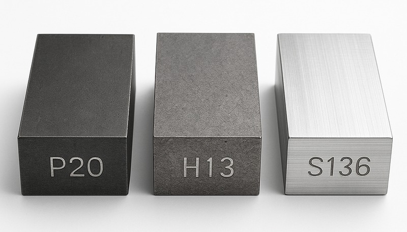
Nach Abschluss aller sechs Zonen sollte das Prüfprotokoll Folgendes dokumentieren: Zustand der Zone (gut/beobachten/Maßnahme erforderlich), Messwerte im Vergleich zu den Basiswerten, Fotos aller Auffälligkeiten und die empfohlene Maßnahme mit Dringlichkeit (vor dem nächsten Lauf / innerhalb von 10,000 Schuss / bei der nächsten planmäßigen PM).
Praktischer Hinweis: Liegt für Ihr Werkzeug keine Referenzdokumentation mit Messwerten aus der T1-Qualifizierung vor, wird die erste Inspektion zur Referenz. Beginnen Sie besser jetzt, statt auf einen idealen Ausgangspunkt zu warten, der möglicherweise nie eintritt.
Wie Sie einen Inspektionsplan erstellen, der tatsächlich funktioniert
Ein wirksamer Inspektionsplan richtet sich nach der Schusszahl und nicht nach der verstrichenen Kalenderzeit — denn eine rund um die Uhr laufende Form muss wesentlich früher geprüft werden als eine Form, die nur zwei Schichten pro Woche im Einsatz ist.
„Die Schusszahl ist ein zuverlässigerer Auslöser für eine Inspektion als die verstrichene Kalenderzeit.“True
Der Werkzeugverschleiß ist direkt proportional zur Anzahl der gefahrenen Zyklen und nicht zu den verstrichenen Tagen. Ein Werkzeug im Dreischichtbetrieb erreicht in etwa drei Wochen 50,000 Schuss; dasselbe Werkzeug benötigt im Einschichtbetrieb neun Wochen. Kalenderbasierte Wartungspläne führen entweder zu einer unzureichenden Prüfung stark ausgelasteter Werkzeuge oder verschwenden Zeit für stillstehende Werkzeuge.
„Alle Werkzeuge sollten unabhängig von Material oder Kavitätenzahl demselben Prüfintervall folgen.“False
Glasfaserverstärktes Polyamid verursacht in einem Werkzeug mit 32 Kavitäten pro Zeiteinheit wesentlich mehr abrasiven Verschleiß als unverstärktes ABS in einem Werkzeug mit 4 Kavitäten. Die Prüfintervalle müssen an die Abrasivität des Werkstoffs, die Kavitätenzahl und die Kritikalität des Bauteils angepasst werden. Ein einheitlicher Wartungsplan schützt entweder stark beanspruchte Werkzeuge unzureichend oder verschwendet Ressourcen für Werkzeuge mit geringem Risiko.
Ein praxisgerechter gestufter Wartungsplan für Spritzgussformen sieht wie folgt aus. Bei 10,000 Schuss: kurze Sichtprüfung — Grat an der Trennlinie, Erscheinungsbild des Teils, ungewöhnliche Geräusche oder Zyklusabweichungen. Bei 50,000 Schuss: vollständige Inspektion aller sechs Zonen, Reinigung der Entlüftungen, Schmierung der Auswerferstifte und Durchflussprüfung der Kühlkanäle. Bei 200,000 Schuss: Maßprüfung von Kavität und Kern, Messung des Anschnittverschleißes, Prüfung des Auswerferstiftdurchmessers und stichprobenartige Prüfung der Stahlhärte in Bereichen mit hohem Verschleiß. Bei 500,000+ Schuss: vollständige Maßvermessung, Entkalkung der Kühlkanäle und geführte Ultraschallwellenprüfung des Stahls auf Risse unter der Oberfläche.
Diese Intervalle verkürzen oder verlängern sich je nach Material. Bei der Verarbeitung von Nylon mit 30% Glasfaseranteil: Intervalle halbieren. Bei unverstärktem Standard-PP: um 30–50% verlängern. Bei korrosiven Materialien (PVC, halogenhaltige flammgeschützte Typen): monatliche pH-Prüfung des Kühlwassers und jährliche Spülung mit Korrosionsinhibitor ergänzen.
| Werkstoff | Abrasivität | Empfohlenes Prüfintervall | Prioritätszone |
|---|---|---|---|
| Ungefülltes PP / PE | Niedrig | Alle 75,000 Schuss | Entlüftungen, Kühlung |
| ABS / HIPS | Niedrig–mittel | Alle 50,000 Schüsse | Trennebene, Entlüftungen |
| PA6 / PA66 unverstärkt | Mittel | Alle 50,000 Schüsse | Anschnitt, Kühlung |
| PA66-GF30 | Hoch | Alle 25.000 Schuss | Anguss, Kavität, Auswerfer |
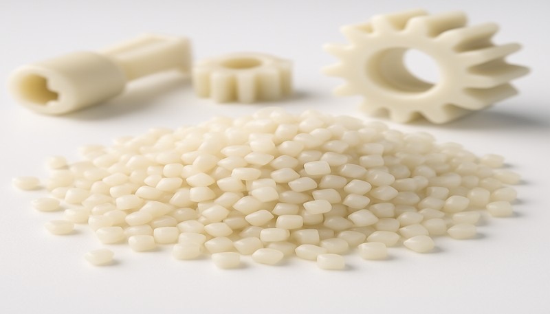
| POM (Polyacetal) | Mittel | Alle 40,000 Schuss | Entlüftungen, Kavitätsoberfläche |
| PVC / halogenhaltiges FR | Korrosiv | Alle 30,000 Schuss + pH-Prüfung | Kühlung, Trennfuge |
Dokumentieren Sie jede Inspektion in einem Formenprotokoll — entweder in einem physischen Ordner, der bei der Form aufbewahrt wird, oder als digitalen Datensatz in Ihrem ERP/MES. Das Protokoll sollte Folgendes enthalten: Formen-ID, Schusszahl zum Inspektionszeitpunkt, Name des Prüfers, Zustand nach Zonen, Fotos der Verschleißbereiche, durchgeführte Maßnahmen und Auslöser für die nächste Inspektion. Eine Form ohne vollständiges Protokoll stellt ein Risiko dar: Wenn etwas ausfällt, fehlen Ihnen die Daten, um festzustellen, ob die Ursache eine mangelhafte Wartung oder eine konstruktive Grenze war.
Häufige Schimmelpilzdefekte, die bei der Inspektion erkannt werden – und ihre Ursachen
Die Prüfung erkennt fünf Fehlerkategorien, die für über 80% der formbezogenen Produktionsausfälle verantwortlich sind.
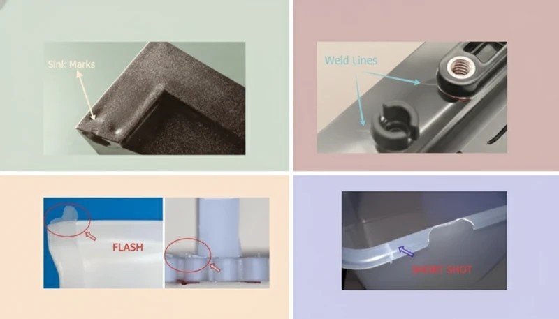
Grat ist der häufigste und sichtbarste Werkzeugfehler. Er tritt als dünne Kunststofffahne entlang der Trennebene, an Entlüftungsstellen oder um Auswerferstifte auf. Grundursache: verschlissene oder beschädigte Trennflächen, unzureichende Schließkraft für die Viskosität des Materials oder Entlüftungen, die auf eine falsche Tiefe gereinigt wurden und nun Material eindringen lassen. Prüfpunkt: Ebenheitsprüfung der Trennebene und Fühlerlehrentest.
Kurzschüsse — unvollständig gefüllte Bauteile — sind häufig auf blockierte Entlüftungen und nicht nur auf Prozessparameter zurückzuführen. Kann das Gas nicht schnell genug aus der Kavität entweichen, entsteht eine Gegendruckzone, die die Fließfront stoppt. Prüfpunkt bei der Inspektion: Messung von Tiefe und Zustand der Entlüftungen.
Einfallstellen und Bindenähte können sich mit zunehmender Verkalkung der Kühlkanäle schrittweise entwickeln. Eine 0.5mm starke Ablagerungsschicht kann die Kavitätsoberflächentemperatur um 8–12°C erhöhen, dadurch die Materialviskosität an der Fließfront verändern und die Festigkeit der Bindenaht verschlechtern. Prüfschwerpunkt: Endoskopische Inspektion der Kühlkanäle und Temperaturdifferenz zwischen Ein- und Auslass.
Auswerfer- und Oberflächenfehler
Abdrücke von Auswerferstiften und Bauteilverformung weisen auf verschlissene oder falsch ausgerichtete Auswerferkomponenten hin. Beginnende Klemmung der Stifte belastet das Teil beim Auswerfen ungleichmäßig und verursacht Verformungen, Oberflächenmarken oder Risse. Prüfpunkt: Kontrolle des Auswerferstiftdurchmessers und Klemmprüfung (manuelle Betätigung der Auswerferplatte).
Eine Verschlechterung der Oberflächenbeschaffenheit – bei optischen oder Class-A-Teilen als Schleier, Schleifspuren oder Texturverlust sichtbar – kann durch Korrosion der Kavität, Anschnittverschleiß mit Materialablagerungen an der Kavitätswand oder mikroskopische Oberflächenrisse im Stahl verursacht werden. Prüfschwerpunkt: Untersuchung der Kavitätsoberfläche und Vergleich mit dem ursprünglichen Standard der Oberflächenbeschaffenheit.
“Verstopfte Entlüftungen sind eine der wichtigsten verborgenen Ursachen für Kurzschüsse, unabhängig von den Einspritzparametern.”True
Wenn Entlüftungen durch Kunststoffausgasungen und Ablagerungen verstopfen, wirkt das in der Kavität eingeschlossene Gas der Fließfront entgegen. Die Spritzgießmaschine registriert einen steigenden Druck und der Bediener erhöht die Füllgeschwindigkeit – dadurch verschärft sich die Gaskompression. Die Grundursache liegt in der Wartung, nicht im Prozess. Inspektion und Reinigung der Entlüftungen beheben das Problem; eine Erhöhung des Einspritzdrucks nicht.
“Verschleiß der Entformungsschräge3 ist bei einer kurzen Sichtprüfung mit bloßem Auge erkennbar.”False
Eine Erosion des Entformungswinkels um 0.1–0.3° — ausreichend für konstanten Entformungswiderstand oder Schäden an der Teileoberfläche — ist ohne Maßprüfung nicht sichtbar. Eine Sichtprüfung zeigt Oberflächenspuren erst nachträglich; dann sind bereits Hunderte oder Tausende Teile betroffen. Nur die vorbeugende Messung der Flächen mit einem Profilometer oder Konturmessgerät erkennt dies zuverlässig.
Eine Faustregel aus der Fertigung: Wenn ein Fehler am fertigen Teil sichtbar ist und sich über Tausende Schüsse schrittweise entwickelt hat, gab es mit großer Wahrscheinlichkeit ein Zeitfenster für eine Werkzeugprüfung, in dem er kostengünstig hätte erkannt und behoben werden können. Das allmähliche Auftreten von Grat, unvollständigen Füllungen und Einfallstellen ist das Kennzeichen fortschreitenden Verschleißes — genau jene Art der Verschlechterung, die durch Prüfungen rechtzeitig erkannt werden soll.
Werkzeuge und Techniken für bessere Werkzeuginspektionen
Eine gut ausgestattete Werkzeugprüfstation nutzt sechs Werkzeugkategorien, die jeweils einem anderen Diagnosezweck dienen.
Werkzeuge für die Sichtprüfung: helle LED-Arbeitsleuchten (mindestens 5,000 lux), 10×- und 30×-Lupen sowie faseroptische Lichtleiter für tiefe Kavitäten. Diese Grundausstattung muss jeder Werkzeugbau besitzen. Sie erkennt Oberflächenschäden, Verunreinigungen, Rost und offensichtlichen Verschleiß.
Maßprüfung: Messuhren (Auflösung 0.001mm) für die Ebenheit der Trennlinie, Lehrdorne für Auswerferstiftbohrungen und Angussmaße, Tiefenmikrometer für die Entlüftungstiefe sowie optische Komparatoren oder CMM für vollständige Kavitätsprüfungen. Maßprüfungen machen aus einer qualitativen Beobachtung eine nachverfolgbare Kennzahl.
Diagnose des Kühlsystems: Industrie-Endoskope (5–8mm Durchmesser, 1m Länge) zur Prüfung der Kanalwände, aufsteckbare Durchflussmesser für den Wasserdurchfluss und digitale Thermometer für die Temperaturdifferenz zwischen Ein- und Auslass. Der Zustand des Kühlsystems lässt sich von außen am schwersten visuell prüfen — nur mit Endoskopen sind die Kanalwände ohne Demontage sichtbar.
Fortgeschrittene Prüfverfahren
Zerstörungsfreie Prüfung (NDT): Farbeindringprüfung (PT) zum Erkennen von Oberflächenrissen in Stahl, Ultraschallprüfung (UT) zum Erkennen unter der Oberfläche liegender Risse in Werkzeugen mit hohen Zykluszahlen und Wirbelstromprüfung zur Kontrolle der Härte in Verschleißzonen. NDT wird üblicherweise für Werkzeuge nach 500,000 Schuss oder für Werkzeuge eingesetzt, die einen Crash, eine Überlastung oder einen ungeklärten Ausfall erfahren haben.
Dokumentationsmittel: Kamera mit Makrofunktion zum Fotografieren von Verschleißbereichen, digitale Messschieber mit Datenausgang zur direkten Übertragung von Messwerten in eine Tabelle sowie ein standardisiertes Inspektionsformular auf Papier oder Tablet, das sicherstellt, dass jeder Bereich bei jeder Prüfung kontrolliert wird.

Die wichtigste Verbesserung der Werkzeugprüfung, die die meisten Betriebe umsetzen können, ist nicht ein besseres Boroskop oder eine CMM, sondern ein einheitliches Prüfformular. Ohne strukturierte Checkliste hängt die Prüfqualität vollständig davon ab, wer prüft und wie viel Zeit dafür verfügbar ist. Ein Formular erzwingt Vollständigkeit. Es schafft außerdem die historischen Aufzeichnungen, die eine Trendanalyse ermöglichen: Wann zeigte die Trennfuge erstmals messbaren Verschleiß? Wie schnell schreitet er fort? Diese Antworten entscheiden, ob das Werkzeug weitere 50,000 Schüsse laufen kann oder sofort aus der Produktion genommen werden muss.
Bei Formen, die eine Spritzgussformkonstruktion mit engen Toleranzen unterstützen, hilft eine erneute Füllsimulation nach größeren Reparaturen zu bestätigen, dass die korrigierte Geometrie weiterhin ordnungsgemäß gefüllt wird, bevor die Produktion freigegeben wird.
Wie Sie Ihr Formeninspektionsprogramm verbessern können
Bei der Verbesserung der Werkzeugprüfung geht es nicht um bessere Ausrüstung, sondern um ein System, das Verschlechterungen so früh wie möglich erkennt und die Befunde ausreichend für datenbasierte Entscheidungen dokumentiert.
Schritte 1–3: Das Fundament schaffen
Schritt 1: Prüfen Sie die Vollständigkeit Ihrer aktuellen Werkzeugprotokolle. Kontrollieren Sie jedes Produktionswerkzeug darauf, ob ein Werkzeugprotokoll mit Schusszahlaufzeichnungen, dem Datum der letzten Inspektion und dem Zustandsverlauf vorhanden ist. In den meisten Betrieben zeigt diese Prüfung, dass für 30–50% der Werkzeuge unvollständige oder gar keine Aufzeichnungen vorliegen. Das ist die Ausgangslücke – sie zu schließen ist die Verbesserung mit der höchsten Priorität.
Schritt 2: Stellen Sie auf schusszahlbasierte Auslöser um. Wenn Sie Inspektionen derzeit nach Kalendermonaten planen, wechseln Sie zu Auslösern auf Basis der Schusszahl. Dazu müssen die Daten der Schusszähler an den Spritzgießmaschinen in Ihr Planungssystem integriert werden. Die meisten modernen Spritzgießmaschinen stellen Schusszahldaten über eine Euromap- oder OPC-UA-Schnittstelle bereit; bei älteren Maschinen kann die Nachrüstung eines einfachen mechanischen Zählers für unter $200 erforderlich sein.
Schritt 3: Standardisieren Sie Ihre Prüfcheckliste. Erstellen Sie ein einseitiges Formular, das alle sechs Bereiche abdeckt. Jeder Prüfer verwendet dasselbe Formular, dokumentiert Messwerte (nicht nur bestanden/nicht bestanden) und unterzeichnet es. Werten Sie die Formulare monatlich aus, um Trends im gesamten Werkzeugbestand zu erkennen.
Schritte 4–6: Kontinuierliche Verbesserung vorantreiben
Schritt 4: Implementieren Sie Frühwarnkennzahlen aus Produktionsdaten. Eine Schwankung der Zykluszeit von Schuss zu Schuss um mehr als ±0.5 Sekunden ist oft das früheste Anzeichen für ein Formenproblem — noch bevor ein Fehler am Teil sichtbar wird. Daten von Kavitätsdrucksensoren (falls vorhanden) können zeigen, wie sich über Tausende von Schüssen ein Ungleichgewicht bei der Füllung entwickelt. Mit diesen Frühindikatoren können Sie die Form zur Inspektion ausbauen, bevor Fehler auftreten.
Schritt 5: Schulen Sie Bediener darin, Abweichungen in Echtzeit zu melden. Die Person an der Presse ist die erste Instanz der Werkzeugüberwachung. Ungewöhnliche Geräusche, sichtbarer Grat an Bauteil 1 einer Schicht oder ein klemmendes Bauteil beim Auswerfen sind Prüfzeichen – jedoch nur, wenn der Bediener weiß, dass er sofort eskalieren muss, statt weiterzuproduzieren und auf eine Selbstbehebung zu hoffen. Ein einfaches „Stopp-und-melden“-Protokoll für bestimmte Abweichungen amortisiert sich bereits, wenn erstmals ein beginnendes Klemmen eines Auswerferstifts erkannt wird.
Schritt 6: Schließen Sie den Regelkreis zwischen Prüfbefunden und Konstruktion. Wenn derselbe Bereich wiederholt ausfällt — beispielsweise wenn der Anschnittbereich trotz planmäßiger Wartung alle 30,000 Schüsse erodiert — ist dies ein Konstruktionssignal und nicht nur ein Wartungsproblem. Die Lösung kann ein härteres Material für den Anschnitteinsatz, eine Geometrieänderung oder eine Formfüllanalyse sein, um zu verstehen, warum sich dort Schubspannung konzentriert. Prüfdaten, die in die Konstruktionsverbesserung zurückfließen, stellen die hochwertigste Nutzung dieser Informationen dar.
Diese sechs Schritte sind kein einmaliges Projekt, sondern eine fortlaufende Betriebsdisziplin. Betriebe, die sie konsequent umsetzen, verzeichnen weniger ungeplante Formausbauten, eine längere durchschnittliche Werkzeugstandzeit und geringere Ausschussquoten. Nach unserer Erfahrung mit 47 Spritzgießmaschinen im Dreischichtbetrieb beträgt der vermeidbare Kostenunterschied zwischen einem gut geführten Prüfprogramm und reaktiver Wartung typischerweise 15–20% der jährlichen Gesamtwerkzeugkosten.
Ein letzter praktischer Hinweis: Beginnen Sie mit den vorhandenen Werkzeugen. Eine Fühlerlehre, eine helle Taschenlampe und ein Notizbuch genügen, um Ausgangsdaten für Ihre wichtigsten Werkzeuge zu erfassen. Perfekte Ausrüstung kommt später — nachdem Sie die nötige Disziplin bewiesen haben. Entscheidend in der Anfangsphase jedes Prüfprogramms ist die Disziplin, regelmäßig und dokumentiert hinzusehen. Was nicht gemessen wird, kann nicht verbessert werden, und was nicht nach einem konsequenten, dokumentierten Zeitplan geprüft wird, kann nicht gemessen werden.
Wo beginnen?
Bei Kleinserien-Spritzgießen oder Prototypenwerkzeugen können die Prüfintervalle größer sein, doch derselbe Sechs-Zonen-Rahmen gilt weiterhin. Das Ziel bleibt gleich: den aktuellen Werkzeugzustand vor dem nächsten Lauf kennen, nicht erst nach dem nächsten Produktionsproblem.
Die häufigste Frage von Kunden, die ihr Prüfprogramm erweitern, lautet: „Wo fangen wir an?“ Die Antwort ist immer dieselbe: Beginnen Sie mit Ihrem Werkzeug mit dem höchsten Produktionsvolumen und dem größten Risiko. Suchen Sie dessen Werkzeugprotokoll heraus oder legen Sie eines neu an und verwenden Sie den heutigen Tag als Tag null. Bauen Sie das Werkzeug aus der Maschine aus, prüfen Sie es mithilfe der Checkliste in diesem Artikel in allen sechs Zonen und dokumentieren Sie jeden Messwert, nicht nur die auffälligen Bereiche. Planen Sie die nächste Prüfung anhand der Schusszahl unter Berücksichtigung von Material und Kavitätenzahl. Alles Weitere – bessere Werkzeuge, Datenintegration und Bedienerschulung – ergibt sich folgerichtig aus diesem ersten ordnungsgemäß dokumentierten Prüfzyklus.
Häufig gestellte Fragen zur Schimmelpilzinspektion
Wie oft sollte eine Spritzgussform inspiziert werden?
Standard-Serienformen sind mindestens alle 50,000 Zyklen zu prüfen. Anwendungen mit hohem Verschleiß — glasfaserverstärkte Harze mit 30% oder mehr, Werkzeuge mit vielen Kavitäten oder korrosive Materialien wie PVC — erfordern alle 25,000 Zyklen eine Prüfung. Prototypenformen für geringe Stückzahlen können bei unverstärkten Materialien bis zu 100,000 Zyklen zwischen vollständigen Prüfungen erreichen. Maßgeblich ist stets die Zykluszahl, nicht die Kalenderzeit. Eine Form, die eine Schicht pro Woche läuft, sammelt wesentlich langsamer Zyklen als ein 24/7-Serienwerkzeug; eine kalenderbasierte Planung führt daher je nach Produktionsvolumen zu übermäßiger oder unzureichender Prüfung.
Welche sind die häufigsten Mängel, die bei der Schimmelpilzuntersuchung festgestellt werden?
Grat an der Trennebene macht 35–40% der bei routinemäßigen Werkzeugprüfungen festgestellten Fehler aus. Es folgen verstopfte Entlüftungen (25%), verschlissene oder klemmende Auswerferstifte (15%), Verunreinigung oder Beschädigung der Kavitätsoberfläche (12%) und Ablagerungen in Kühlkanälen (8%). Jeder Fehlertyp lässt sich direkt einer bestimmten Prüfzone und Messmethode zuordnen. Grat weist auf Verschleiß der Trennebene hin, Kurzschüsse auf blockierte Entlüftungen und Oberflächenmarken auf Auswerferprobleme. Einfallstellen oder Maßdrift gehen häufig auf Ablagerungen im Kühlsystem zurück, die die Kavitätstemperatur erhöhen und das Füllverhalten verändern.
Kann die Schimmelpilzinspektion durchgeführt werden, ohne den Schimmel aus der Presse zu entfernen?
Eine Teilprüfung kann in der Maschine zwischen zwei Schusszyklen erfolgen: Sichtprüfung der Trennebene auf Grat, Untersuchung der Teileoberfläche auf Schleifspuren oder Veränderungen der Oberflächengüte und Gratkontrolle an den Entlüftungsstellen. Für eine vollständige Prüfung — einschließlich Entlüftungen, Kühlkanälen, Auswerfersystem und Kavitätsabmessungen — muss das Werkzeug jedoch aus der Maschine ausgebaut und auf einem Prüfplatz mit geeigneter Beleuchtung und Messtechnik abgelegt werden. Prüfungen in der Maschine dienen zwischen den geplanten Vollprüfungen als Frühwarnüberwachung, ersetzen aber keine gründliche Bewertung außerhalb der Maschine.
Was kostet eine typische Schimmelpilzinspektion?
Eine vollständige Inspektion eines Zweiplattenwerkzeugs mittlerer Komplexität erfordert 4–8 Technikerstunden und verursacht $200–$600 an Arbeitskosten zuzüglich der für Reinigung und Schmierung verwendeten Verbrauchsmaterialien. Kommt eine vollständige Vermessung der Kavität hinzu, sind zusätzlich typischerweise 2–4 Stunden für Maßmessungen einzuplanen. Diese Gesamtkosten von $400–$1,000 stehen in direktem Verhältnis zu den Kosten eines einzigen ungeplanten Produktionsstillstands, der durch Produktionsausfall, beschleunigte Reparatur und Kundenvertragsstrafen typischerweise $5,000–$50,000 verursacht. Eine planmäßige Inspektion nach 50,000 Schuss amortisiert sich bereits beim ersten dadurch verhinderten Notausbau des Werkzeugs.
Welche Werkzeuge sind für eine professionelle Formenprüfung erforderlich?
Zur Grundausstattung gehören eine helle LED-Arbeitsleuchte (mindestens 5,000 lux), eine 10×-Lupe, Fühlerlehren zur Messung des Trennspalts, eine Messuhr für Ebenheitsprüfungen, ein Lehrdornsatz für Auswerferbohrungen und Anschnittmaße, ein Tiefenmikrometer zur Messung der Entlüftungstiefe sowie eine Digitalkamera zur Dokumentation. Für erweiterte Prüfungen kommen ein Industrieendoskop (5–8mm Durchmesser) zur Kontrolle der Kühlkanäle, ein tragbares CMM oder ein optischer Komparator zur Maßprüfung der Kavität und ein Farbeindringprüfsatz zur Erkennung von Oberflächenrissen hinzu. Die meisten Betriebe beginnen mit der Grundausstattung und ergänzen bei steigender Werkzeugkomplexität und höheren Produktionsvolumen weitere Prüfmittel.
Wie verhält sich Schimmelpilzinspektion zu Schimmelpilzwartung?
Inspektion dient der Diagnose, Wartung der Korrektur. Die Inspektion ermittelt den Handlungsbedarf — Entlüftungen reinigen, einen verschlissenen Auswerferstift ersetzen oder einen Kühlkanal entkalken. Die Wartung führt diese Maßnahmen aus. Eine Wartung nach festem Zeitplan ohne vorherige Inspektion kann Zeit für die Reinigung eines einwandfreien Werkzeugs verschwenden, während ein gerissenes Bauteil in einem benachbarten Werkzeug unberücksichtigt bleibt. Die richtige Reihenfolge ist stets: zuerst prüfen, anschließend gezielte Wartungsmaßnahmen anhand der Befunde durchführen. Dieser Ansatz verhindert sowohl unzureichende Wartung als auch unnötigen Wartungsaufwand.
Welche Aufzeichnungen sollten für jede Formeninspektion geführt werden?
Erfassen Sie die Schusszahl zum Prüfzeitpunkt, das Datum und den Namen des Prüfers. Dokumentieren Sie den Zustandswert für jeden der sechs Bereiche — Kavitätsoberfläche, Trennebene, Entlüftungen, Auswerfersystem, Kühlkanäle und Anguss/Anschnitt — anhand tatsächlicher Messwerte im Vergleich zur Ausgangsbasis, nicht nur als bestanden/nicht bestanden. Fotografieren Sie sämtliche Verschleißstellen oder Auffälligkeiten. Dokumentieren Sie die bei dieser Prüfung ergriffenen Maßnahmen und legen Sie den Auslöser für die nächste Prüfung anhand der Schusszahl fest. Ein vollständiges Formenprotokoll ermöglicht Trendanalysen über mehrere Prüfzyklen hinweg und liefert damit die wertvollsten Erkenntnisse, die ein Prüfprogramm hervorbringen kann.
Faustregel: Standardwerkzeuge nach 50,000 Schuss, bei abrasiven Materialien nach 25,000 Schuss prüfen. Dokumentieren Sie jeden Befund mit Messwerten statt mit Eindrücken. Fällt derselbe Bereich zweimal hintereinander aus, ist dies als Konstruktionssignal zu behandeln — nicht nur als Wartungsproblem. Und wenn für Ihre Werkzeuge keine Schusszahlen erfasst werden, beginnen Sie noch heute damit; diese Daten sind die Grundlage für alles Weitere.
Trennebene: Die Trennebene ist die Naht am Formteil, an der die beiden Formhälften beim Auswerfen zusammentreffen und sich trennen. Sie ist häufig der erste Hinweis auf Formverschleiß oder Gratbildung; ihre Ebenheit wird bei jeder strukturierten Forminspektion gemessen. ↩
Bindenaht: Eine Bindenaht bezeichnet die sichtbare Naht, die entsteht, wenn zwei Kunststoff-Fließfronten in der Formkavität aufeinandertreffen und sich unvollständig verbinden. Sie weist typischerweise auf ein Kühlungs- oder Druckungleichgewicht hin, das bei einer Inspektion erkannt werden kann. ↩
Entformungsschräge: Die Entformungsschräge wird in Grad gemessen und bezeichnet die Neigung vertikaler Formflächen, damit sich das Bauteil beim Auswerfen sauber löst. Eine unzureichende Entformungsschräge ist eine häufige Grundursache für Auswurfschäden, die bei Routineinspektionen festgestellt werden. ↩
Erhalten Sie wettbewerbsfähige Preise, DFM-Feedback und einen Produktionszeitplan vom Ingenieurteam von ZetarMold.
Kostenloses Angebot anfordern → Eine umfassende Übersicht finden Sie in unserem vollständigen Leitfaden zum Spritzgießen. Eine umfassende Übersicht finden Sie in unserem vollständigen Leitfaden zum Spritzgießen.