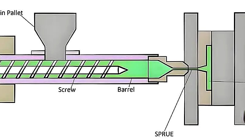
Sie haben gerade einen Eilauftrag für fünf verschiedene Kunststoffabdeckungen erhalten, die jeweils eine eigene Form benötigen. Ihre Fertigung ist vollständig ausgelastet, und der Gedanke, fünf Formen in voller Größe zu wechseln — wobei jeder Wechsel zwei bis vier Stunden beansprucht — macht Ihren Zeitplan unmöglich. Ein MUD-Spritzgießformsystem ist genau für diese Situation ausgelegt: Ein Universalrahmen bleibt in der Maschine, und Sie wechseln leichte Einsatzformen in wenigen Minuten statt in mehreren Stunden.
Dieser Artikel erläutert, was ein MUD-System tatsächlich ist, wann es sinnvoll ist und wann nicht, wie dafür konstruiert wird und welche Kosten im Vergleich zu konventionellen Werkzeugen entstehen. Ich habe Betriebe gesehen, die MUD-Aufbauten für ungeeignete Anwendungen einsetzten und damit Geld verschwendeten, während andere mit den richtigen Anwendungen Tausende pro Monat sparten — entscheidend ist das Verständnis der Zielkonflikte.
- Ein MUD-System verwendet einen Universalrahmen mit austauschbaren Werkzeugeinsätzen für schnelle Umrüstvorgänge.
- Mit einer MUD-Schnellwechselbasis dauern Werkzeugwechsel Minuten statt Stunden.
- MUD-Werkzeuge eignen sich am besten für Kleinserien, Mehrkomponentenprojekte oder Prototypenläufe.
- Begrenzungen bei Einsatzgröße und Schussvolumen machen MUD für große Bauteile oder Anwendungen mit hoher Kavitätenzahl ungeeignet.
- Ein MUD-Einsatz kostet 40–60% weniger als ein vollständiger konventioneller Werkzeugaufbau.
Was ist eine MUD-Spritzgussform?
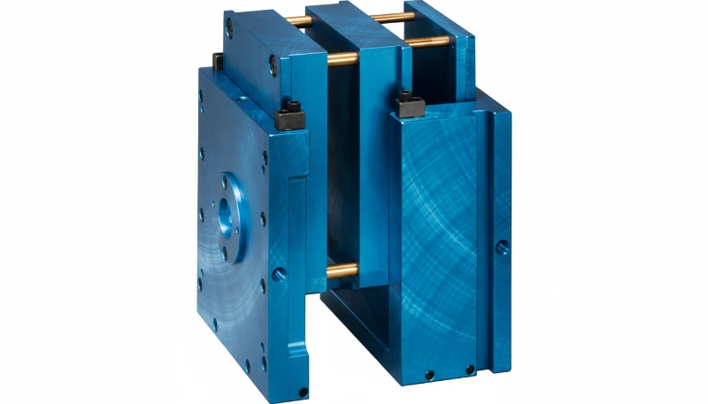
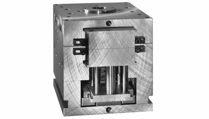
Eine MUD-Spritzgussform ist ein Schnellwechsel-Werkzeugsystem, bei dem eine standardisierte Formbasis1 in der Spritzgussmaschine montiert bleibt. Anstatt bei jedem Produktwechsel eine vollständige Form zu entfernen, tauscht der Bediener einen kleineren Einsatz aus, der die Kavität und den Kern enthält. Dies reduziert die Rüstzeit, wenn mehrere verwandte Teile dieselbe Druckmaschine, Materialfamilie und dasselbe Produktionsfenster verwenden.
Stellen Sie es sich wie eine Bohrmaschine vor: Die Bohrmaschine selbst bleibt in Ihrer Hand und Sie tauschen einfach den Bohrer aus. Der MUD-Rahmen ist der Bohrer; die Einsatzform2 ist das Bit. Die Standardrahmengrößen reichen von etwa 6 Zoll bis 18 Zoll und eignen sich für Einsatzformen unterschiedlicher Grundfläche. Jeder Rahmen umfasst Führungsstifte, Buchsen und Klemmmechanismen, die den Einsatz ausrichten und in seiner Position fixieren.
In unserem Betrieb haben wir MUD-artige Rahmen für Aufträge eingesetzt, bei denen mehrere kleine Bauteile derselben Werkstofffamilie benötigt werden, etwa Steckverbindergehäuse, kleine Abdeckungen und Sensorgehäuse. Einsätze wechseln zu können, ohne das gesamte Werkzeug aus der Maschine auszubauen, spart erheblich Zeit, wenn mehrere SKUs unmittelbar nacheinander gefertigt werden. Mit 47 Spritzgießmaschinen von 90T bis 1850T verfügen wir über die Flexibilität, bestimmte Maschinen für derartige Schnellwechsel-Werkzeugkonfigurationen vorzusehen. Unser Produktionsteam kann Einsätze schnell wechseln, ohne die Bauteilqualität oder Maschinenverfügbarkeit zu beeinträchtigen.
Der wesentliche Unterschied zu einem Standardwerkzeug besteht darin, dass der MUD-Rahmen die gesamte Infrastruktur übernimmt: Ausrichtung, Auswerferhub und Maschinenmontage. Der Einsatz konzentriert sich auf die Bauteilgeometrie. Diese Trennung ermöglicht sowohl Kosteneinsparungen als auch schnellere Werkzeugwechsel. Für ein neues Teil wird nicht jedes Mal das Rad neu erfunden, sondern nur der Reifen gewechselt. Der zusätzliche Planungsspielraum schützt außerdem die Zeit für die Bemusterung.
Wie funktioniert ein MUD-Schnellwechselsystem?
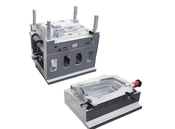
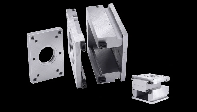
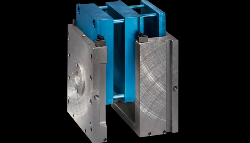
Ein MUD-Schnellwechselsystem ist eine kontrollierte Prozessfolge, die die in diesem Abschnitt erläuterten Phasen und Einstellungen durchläuft. Das MUD-System besteht aus drei Hauptkomponenten: dem Stammrahmen, dem Einsatzwerkzeug und dem Verriegelungsmechanismus. Der Stammrahmen wird wie ein herkömmliches Werkzeug an die Aufspannplatten der Presse geschraubt. Er enthält die Auswerferplattenbaugruppe, Führungsstiftsätze, Stützpfeiler und eine bearbeitete Aufnahme, deren Größe für eine bestimmte Einsatzklasse ausgelegt ist.
Das Einsatzwerkzeug ist eine eigenständige Einheit, die Kern, Kavität, Angusskanalsystem und eigene Kühlkreisläufe enthält. Beim Produktionswechsel von Teil A zu Teil B öffnet der Bediener die Maschine, löst die Klemmung des aktuellen Einsatzes, zieht ihn heraus, setzt den neuen Einsatz ein, klemmt ihn fest und schließt das Werkzeug. Der gesamte Vorgang dauert in der Regel 10 bis 30 Minuten, abhängig von der Rahmengröße und der Komplexität der Kühl- und Auswerferanschlüsse.
Einige fortschrittliche MUD-Systeme integrieren Schnellkupplungen für Wasserleitungen und elektrische Anschlüsse und verkürzen damit die Wechselzeit weiter. Statt einzelne Kühlmittelschläuche manuell an- und abzuschrauben, verbindet der Bediener einen einzigen Verteilerblock, der das Kühlwasser zu den richtigen Kanälen im Einsatz führt. Diese Schnellkupplungen erhöhen die Anfangskosten des Rahmens, amortisieren sich jedoch in einer variantenreichen Fertigung, in der Einsätze drei- oder viermal pro Schicht gewechselt werden, schnell.
Vergleichen Sie dies mit einem konventionellen Formwechsel: Die Form muss mit einem Kran oder Gabelstapler aus der Presse gehoben, alle Wasserleitungen und elektrischen Anschlüsse müssen getrennt und eine möglicherweise mehrere hundert Kilogramm schwere Form muss bewegt werden. Für die neue Form läuft der gesamte Prozess anschließend umgekehrt ab. Selbst unter günstigen Bedingungen entstehen dadurch zwei bis vier Stunden Stillstand.
Die Verriegelungsmechanismen unterscheiden sich je nach Hersteller. Das ursprüngliche MUD-System von DME verwendet eine keilförmige Klemmung, die seitlich angezogen wird. Andere Systeme verwenden hydraulische Spannvorrichtungen, Kniehebelverriegelungen oder Bajonett-Schnellverschlüsse. Für Sie als Ingenieur ist entscheidend, wie sich die Verriegelungsmethode auf die Einsatzausrichtung auswirkt — bereits ein Versatz von wenigen Tausendstel Zoll führt zu Grat oder zu Teilen außerhalb der Toleranz.
In unserer Produktionsplanung sind Werkzeuge im MUD-Stil besonders sinnvoll, wenn Einsatzwechsel auf kompatiblen Maschinen ohne lange Rüstfenster ausgeführt werden können. ZetarMold verfügt über 20+ Jahre Erfahrung im Formenbau und 47 Spritzgießmaschinen von 90T bis 1850T. Daher können unsere Ingenieure Einsatzgröße, Schließkraft, Werkstoff und erwartete Wechselhäufigkeit abgleichen, bevor sie ein MUD-Grundgestell empfehlen.
Wann sollten Sie ein MUD-System einsetzen?
Dieser Abschnitt behandelt den Einsatz eines MUD-Systems und dessen Auswirkungen auf Kosten, Qualität, Terminplanung oder Beschaffungsrisiken. MUD-Systeme sind in bestimmten Szenarien besonders vorteilhaft. Im Folgenden zeigen wir anhand unserer Erfahrungen aus mehr als 20 Jahren Serienwerkzeugbetrieb, wo sie tatsächlich Mehrwert schaffen. Allen diesen Anwendungsfällen ist gemeinsam, dass mehrere unterschiedliche Bauteile in relativ kurzen Produktionsfenstern auf derselben Maschine gefertigt werden müssen und das Volumen die Kosten separater Werkzeuge in voller Größe für jedes Bauteil nicht rechtfertigt.
Mehrteilfamilien aus demselben Material
Wenn Sie eine Familie aus fünf kleinen ABS-Gehäusen mit gleicher Wanddicke, gleichem Angusstyp und gleicher Schwindung fertigen, können Sie mit einem MUD-Rahmen alle auf einer Maschine mit minimalem Rüstaufwand produzieren. Dies ist der typische Anwendungsfall. Sie fertigen SKU-1 vier Stunden lang, wechseln die Einsätze, fertigen SKU-2 drei Stunden lang usw. Eine Maschine, ein Rahmen, fünf Einsätze. Noch wirtschaftlicher wird es, weil jeder Einsatz nach seinem eigenen Plan gewartet wird — zur Wartung einer Kavität muss nicht der gesamte Rahmen außer Betrieb genommen werden.
Kleinserien- und Prototypenfertigung
Bei Jahresmengen unter 10,000 Teilen pro SKU sind fünf eigene Werkzeuge in voller Größe finanziell schwer zu rechtfertigen. Fünf MUD-Einsätze zu 40–60% der Kosten von fünf Vollwerkzeugen ergeben dagegen eine sinnvolle Kalkulation. Wir empfehlen diesen Ansatz regelmäßig Kunden, die eine Brückenlösung nach dem Prototyp oder Markttestserien benötigen, bevor sie in Serienwerkzeuge investieren. Auch das Risiko ist geringer: Findet das Produkt keine Marktakzeptanz, verlieren Sie einige Tausend Dollar pro Einsatz statt Zehntausende pro Vollwerkzeug.
Häufige Konstruktionsänderungen
Wenn sich die Konstruktion während der Produktentwicklung alle paar Wochen ändert, ist die Änderung eines kleinen Einsatzes schneller und kostengünstiger als die Überarbeitung eines vollständigen Formaufbaus. Der Einsatz enthält nur die geometriespezifischen Elemente, sodass sich die Änderungskosten auf den Stahl für Kavität und Kern beschränken und nicht die gesamte Rahmenbaugruppe betreffen. Unsere 8 erfahrenen Ingenieure arbeiten während der Validierungsphase regelmäßig mit Kunden an iterativen Einsatzkonstruktionen.
Hinzu kommt ein häufig übersehener Vorteil bei der Produktionsplanung. Muss Ihr Produktionsplaner einen kleinen Eilauftrag zwischen zwei größere Läufe einschieben, ist dies mit einem MUD-Einsatz möglich, ohne den Hauptzeitplan zu beeinträchtigen. Sie fahren den Großauftrag, unterbrechen ihn für 20 Minuten zum Einsetzen des Eileinsatzes, fertigen den Kleinauftrag, wechseln zurück und setzen die Produktion fort. Kein Kran, keine Neukalibrierung der Presse und keine Neuorganisation der Fertigungsfläche.
Welche Einschränkungen haben MUD-Werkzeuge?
Die Einschränkungen von MUD-Formen sind die in diesem Abschnitt erläuterten Hauptkategorien beziehungsweise Optionen. Es wäre nicht ehrlich, nur über die Vorteile zu sprechen. MUD-Systeme haben reale Einschränkungen, durch die sie für viele Anwendungen die falsche Wahl sind.
Erstens, Größenbeschränkungen. MUD-Einsätze sind vom Design her klein. Selbst die größten Standardrahmen (15–18-Zoll-Serie) schränken Ihren maximalen Teilebereich ein. Wenn Ihr Teil in irgendeiner Abmessung größer als etwa 300 mm ist oder mehrere Kavitäten für die Produktion großer Mengen benötigt, funktioniert ein MUD-System nicht. Sie benötigen eine herkömmliche Form in Originalgröße.
Zweitens strukturelle Starrheit. Ein MUD-Einsatz sitzt in einer Tasche im Rahmen, und diese Schnittstelle ist nicht so steif wie eine solide einteilige Form. Unter hohen Einspritzdrücken – insbesondere bei glasfaserverstärkten Materialien – kann es zu einer Trennung der Trennlinie3 oder zu Graten an der Grenze zwischen Einsatz und Rahmen kommen. Für Teile mit engen Toleranzen mit ±0,05 mm oder strengeren Anforderungen kann dieser Flex ein entscheidender Faktor sein.
Drittens Kühlbeschränkungen. Die Einsatzform bietet im Vergleich zu einer Vollform nur begrenzten Platz für Kühlkanäle. Längere Zykluszeiten4 pro Schuss sind üblich, manchmal 15–25 % länger als bei einer entsprechenden herkömmlichen Form. Wenn Sie Millionen von Teilen verarbeiten und es auf jede Sekunde Zykluszeit ankommt, summiert sich der Kühlaufwand schnell.
Viertens: Kavitationsgrenzen. Die meisten MUD-Einsätze bieten Platz für 1 bis 4 Hohlräume. Wenn Ihr Produktionsplan eine Form mit 8 oder 16 Kavitäten vorsieht, um die Volumenziele zu erreichen, kann ein MUD-System nicht liefern. Die Stellfläche des Einsatzes bietet einfach keinen Platz.
"Ein MUD-Einsatzwerkzeug kostet für dasselbe Bauteil 40–60% weniger als ein vollständiges konventionelles Werkzeug."True
Der Einsatz enthält nur Kern, Kavität und grundlegende Kühlung – keinen Rahmen, keine große Auswerferplatte, keine schweren Tragstrukturen. Der gemeinsame Hauptrahmen wird auf alle Einsätze verteilt, sodass Sie bei jedem zusätzlichen Teiledesign Stahl, Bearbeitungszeit und Konstruktionsaufwand sparen.
"MUD-Systeme sind ideal für die Großserienfertigung großer Teile."False
MUD-Einsätze haben strenge Größen- und Kavitätsgrenzen. Große Teile überschreiten den Einschubeinsatz, und Aufträge mit hohen Stückzahlen benötigen Mehrfachkavitätenlayouts, die nicht passen. Für große oder hochvolumige Produktion bleiben konventionelle Vollformwerkzeuge die richtige Wahl.
Wie unterscheidet sich MUD von konventionellen Formaufbauten?
Hier ist ein direkter Vergleich, der widerspiegelt, was wir tatsächlich bei der Angebotserstellung und Produktion sehen, nicht theoretische Lehrbuchzahlen.
| Faktor | MUD Schnellwechsel | Konventionelles Werkzeug |
|---|---|---|
| Anfängliche Formkosten (pro Bauteilkonstruktion) | 40–60 % niedriger | Vollpreis |
| Rüstzeit | 10–30 Minuten | 2–4 Stunden |
| Maximale Teilgröße | ~300 mm (größter Rahmen) | Nur durch Pressengröße begrenzt |
| Maximale Kavitation | 1–4 Kavitäten typisch | 16+ Kavitäten möglich |
| Strukturelle Steifigkeit | Gut (Einsatz-im-Rahmen) | Ausgezeichnet (massiver Block) |
| Auswirkung auf die Zykluszeit | +15–25 % gegenüber konventionell | Ausgangsbasis |
| Am besten geeignet für | Geringes Volumen, mehrere SKUs, Prototyp | Großvolumen, große Teile |
| Kosten für technische Änderungen | Niedrig (nur Einsatz anpassen) | Hoch (vollständige Form modifizieren) |
Die Entscheidung ist nicht immer binär. Einige Betriebe setzen beides ein: konventionelle Formen für ihre hochvolumigen SKUs und einen MUD-Rahmen an einer dedizierten Presse für das lange Ende der niedrigvolumigen Teile. Mit unserer monatlichen Kapazität von über 100 Sätzen Spritzgussformen bauen wir regelmäßig beide Varianten und können Ihnen helfen herauszufinden, welcher Ansatz zu Ihrer spezifischen Produktpalette passt.
„Die Umstellung von konventionellen Formen auf ein MUD-System kann die Umrüststillstandszeit um mehr als 90% reduzieren.“True
Ein konventioneller Formenwechsel dauert 2–4 Stunden (Kran, Wasser/Strom trennen, tauschen, wieder anschließen, verifizieren). Ein MUD-Einsatzwechsel dauert 10–30 Minuten (Presse öffnen, entklemmen, herausschieben, einschieben, klemmen, schließen). Der Unterschied sind 90–95% weniger Stillstand pro Rüstvorgang.
"Jede Spritzgießformkonstruktion kann ohne Kompromisse in einen MUD-Einsatz umgewandelt werden."False
Einsatzgröße, Kühlkanallayout, Komplexität des Auswurfsystems und Anforderungen an das Schussvolumen setzen alle Grenzen. Formen mit komplexen Seitenaktionen, Liftern oder großen Hinterschneidungen passen möglicherweise nicht in das Einsatzvolumen oder behalten die erforderliche Steifigkeit nicht bei.
Welche Designregeln gelten für MUD-Einsatzformen?
Das Entwerfen für ein MUD-System ist nicht dasselbe wie das Entwerfen einer eigenständigen Spritzgussform. Der Einsatz muss innerhalb der Rahmenbeschränkungen funktionieren. Hier sind die Regeln, die in der Praxis am wichtigsten sind.
1. Respektieren Sie den Einsteckumschlag. Jede Rahmengröße hat ein maximales Taschenmaß. Ihr Kern und Hohlraum müssen innerhalb dieser Grenze liegen und über eine ausreichende Wandstärke für die strukturelle Unterstützung verfügen. Entwerfen Sie zunächst das Teil und vergleichen Sie es dann mit den Rahmenspezifikationen, bevor Sie sich an die Werkzeugherstellung machen. Das klingt offensichtlich, aber ich habe gesehen, wie Ingenieure ein Teil entworfen, die Genehmigung eingeholt und dann festgestellt haben, dass es nicht in einen Standard-MUD-Einsatz passt.
2. Planen Sie den Standort Ihres Tors für das Laufsystem des Rahmens. Die meisten MUD-Rahmen haben in der Mitte eine Angussstelle im Standard-Spritzgussdesign. Wenn Ihr Teil einen Randanguss oder einen U-Boot-Anguss erfordert, stellen Sie sicher, dass die Angusskanalanordnung des Einsatzes die Schmelze von dieser festen Angussposition zur optimalen Angussposition am Teil transportieren kann.
3. Minimieren Sie Nebenaktionen. Schiebemechanismen, Heber und zusammengeklappte Kerne fressen sich in den begrenzten Raum innerhalb eines Einsatzes. Jede Nebenwirkung erhöht die Komplexität und verringert den für Kühlkanäle verfügbaren Platz. Wenn Ihr Teil mehr als zwei äußere Hinterschneidungen aufweist, sitzt ein MUD-Einsatz sehr fest – und der Werkzeugkostenvorteil beginnt zu verschwinden.
4. Optimieren Sie die Kühlung innerhalb der Grenzen des Einsatzes. Kühlkreisläufe mit großem Durchmesser können nicht durch einen Kompakteinsatz geführt werden. Verwenden Sie nach Möglichkeit Leitbleche, Bubbler oder optimierte Kanalanordnungen, um die Wärmeableitung auf engstem Raum zu maximieren. Der Kühlungsnachteil ist real, aber gutes Design kann die Lücke schließen.
5. Überprüfen Sie den Auswurfhub gegenüber der Auswurfplatte des Rahmens. Der Hauptrahmen stellt die Auswerferplatte und das Rückführungssystem bereit. Ihr Einsatz muss korrekt mit ihm verbunden sein – Stiftpositionen, Hublänge und Rückholfederkraft müssen alle übereinstimmen. Die meisten Rahmen verwenden ein Standard-Auswerferstift-Gittermuster. Gestalten Sie den Auswurf Ihres Einsatzes so, dass er an diesem Raster ausgerichtet ist.
Wie viel kostet eine MUD-Form im Vergleich zu Standardwerkzeugen?
Die Kosten sind der Grund, warum die meisten Leute überhaupt MUD in Betracht ziehen, also lassen Sie mich Ihnen echte Zahlen aus unserer Angebotserfahrung geben. Dies sind typische Bereiche für eine Einzelkavitätenform für ein kleines Elektronikgehäuse (ca. 80 mm × 50 mm × 25 mm) aus P20-Stahl.
| Kostenkomponente | Nur MUD-Einsatz | Vollständige konventionelle Form |
|---|---|---|
| Masterrahmen (einmalig) | $3,000–$6,000 | Nicht zutreffend (in die Form integriert) |
| Einsatzkernform (pro Teil) | $2,500–$5,000 | $6,000–$12,000 |
| Zusätzliche Einsätze (jeweils) | $2,500–$5,000 | $6,000–$12,000 |
| 5-teilige Familie gesamt | $15,500–$31,000 | $30,000–$60,000 |
| Rüstarbeit pro Wechsel | 15 Min. × 1 Bediener | 3 Std. × 2 Bediener + Kran |
| Produktionsstillstandszeit pro Wechsel | 10–30 min | 2–4 Std. |
Die entscheidende Erkenntnis: Der Masterrahmen ist eine einmalige Investition. Sobald Sie ihn besitzen, kostet jeder zusätzliche Einsatz nur den Einsatzpreis. Bei einer Bauteilfamilie mit fünf Teilen spart der MUD-Ansatz typischerweise 40–50% der gesamten Werkzeuginvestition. Bei einer zehnteiligen Familie nähern sich die Einsparungen 55–60%.
Aber hier ist der Haken, den viele vergessen: Wenn Sie ein Bauteildesign in sehr hoher Stückzahl fertigen – sagen wir 500.000+ Teile pro Jahr – dann bedeutet der Zykluszeitverlust durch begrenzte Kühlung und die Kavitationsgrenzen eines MUD-Einsatzes, dass Ihre Stückkosten tatsächlich höher sind. Die Werkzeugeinsparungen werden durch die Produktionsineffizienz aufgefressen. Für dieses Szenario ist eine dedizierte 8-fach-Kavitation in einer konventionellen Form die wirtschaftlichere Wahl über die Gesamtlebensdauer.
Dank unserer hauseigenen Beschaffung von Formenstahl und unserer kompletten Formenherstellungsanlage (CNC-Maschinen, Drahtschneider, Erodiermaschinen, Schleifmaschinen – 23 spezielle Maschinen) können wir MUD-Einsätze und konventionelle Formen mit wettbewerbsfähigen Lieferzeiten liefern. Der Schlüssel liegt darin, das richtige System für Ihre Produktionsrealität auszuwählen und nicht nur die günstigere Option.
Formbasis: Eine Formbasis bezieht sich auf den standardisierten Rahmen oder das Gehäuse, das den Kern und die Hohlraumeinsätze hält und strukturelle Unterstützung, Ausrichtungsfunktionen und Montageschnittstellen für die Platten der Spritzgießmaschine bietet. ↩
Einlegeform: Eine Einlegeform ist eine kompakte, eigenständige Formeinheit, die in einen standardisierten Formgrundrahmen passt und nur den Kern und die Kavität sowie Kühl- und Auswurfkomponenten enthält, die für ein Teiledesign spezifisch sind. ↩
Trennlinie: Die Trennlinie bezieht sich auf die sichtbare Naht an einem Formteil, an der sich die beiden Hälften der Form treffen und typischerweise als leichte Kante oder Linie auf der Oberfläche des fertigen Produkts erscheint. ↩
Zykluszeit: Die Zykluszeit ist definiert als die Gesamtdauer eines vollständigen Spritzgießzyklus, gemessen von Formschluss zu Formschluss, einschließlich Einspritz-, Pack-, Kühl- und Auswurfphase, typischerweise in Sekunden ausgedrückt. ↩
Häufig gestellte Fragen zu MUD-Spritzgussformen
Wofür steht MUD beim Spritzgießen?
MUD steht für Master Unit Die. Es handelt sich um ein Schnellwechsel-Formgrundplattensystem, das ursprünglich von DME (jetzt Teil der Barnes Group) entwickelt wurde, bei dem ein universeller Rahmen dauerhaft in der Spritzgießmaschine montiert bleibt und kleine austauschbare Einsatzformen ein- und ausgeschoben werden, um schnelle Werkzeugwechsel zu ermöglichen. Der Master-Rahmen enthält das Auswerfersystem, Führungsstifte und den Spannmechanismus, während jeder Einsatz nur den Kern, die Kavität und seine eigenen Kühlkreisläufe enthält. Obwohl MUD eine eingetragene Marke ist, wird der Begriff in der Spritzgießindustrie weitgehend verwendet, um jedes ähnliche Schnellwechsel-Einsatzformsystem unabhängig vom Hersteller zu beschreiben.
Wie lange dauert ein MUD-Einsatzwechsel?
Ein typischer MUD-Einsatzwechsel dauert je nach Rahmengröße und Komplexität der Kühl- und Auswerferanschlüsse 10 bis 30 Minuten. Der Bediener öffnet die Presse, löst den aktuellen Einsatz, schiebt ihn heraus, installiert den neuen Einsatz, spannt ihn ein und schließt die Form. Im Vergleich dazu dauert ein konventioneller vollständiger Formenwechsel 2–4 Stunden, bei dem ein Kran oder Gabelstapler benötigt wird, Wasserleitungen und elektrische Verbindungen getrennt werden müssen, eine mehrere hundert Kilogramm schwere Form physisch bewegt wird und dann der gesamte Prozess umgekehrt abläuft. Für eine Produktionsstätte, die mehrere Kurzläufe pro Tag durchführt, ist diese Zeitersparnis erheblich und führt direkt zu einer höheren Maschinenauslastung und niedrigeren Stückkosten.
Was ist die maximale Bauteilgröße für eine MUD. Form?
Die maximale Bauteilgröße hängt von der spezifischen MUD-Rahmenserie ab, die Sie auswählen. Die größten verfügbaren Standard-MUD-Rahmen (typischerweise die 15–18-Zoll-Serie) können Bauteile mit bis zu etwa 300 mm in ihrer größten Abmessung aufnehmen. Sie müssen jedoch die Wandstärke des Einsatzes und die strukturelle Unterstützung um den Hohlraum herum berücksichtigen, sodass der nutzbare Bauraum etwas kleiner ist als die reine Rahmentaschenabmessung. Bauteile, die diese Größe überschreiten, oder Bauteile, die Mehrfachhohlraum-Anordnungen erfordern, um hohe Produktionsziele zu erreichen, sind besser für konventionelle Vollgrößenformen geeignet, bei denen die einzige praktische Größenbeschränkung die Tonnage und die Aufspannplattenabmessungen Ihrer Spritzgießmaschine sind.
Kann ein MUD-System glasgefüllte oder hochdruckbeständige Materialien verarbeiten?
MUD-Einsätze können glasgefüllte und hochdruckbeständige Materialien formen, aber Sie müssen die strukturellen Grenzen der Einsatz-Rahmen-Schnittstelle berücksichtigen. Da der Einsatz in einer Tasche innerhalb des Master-Rahmens sitzt und kein massiver einteiliger Block ist, ist er unter hohen Einspritzdrucken von Natur aus weniger steif. Bei glasgefüllten Nylonen, PBT oder anderen hochviskosen technischen Kunststoffen, die Einspritzdrucke über 150 MPa erfordern, kann es zu Gratbildung an der Einsatzgrenze oder leichter Trennung der Trennfuge kommen. Für eng tolerierte Bauteile mit ±0,05 mm oder strengeren Anforderungen, die in diesen anspruchsvollen Materialien geformt werden, bietet eine konventionelle massive Form in der Regel eine konsistentere Maßstabilität über die Produktionsläufe hinweg.
Wie viele Kavitäten passen in einen MUD-Einsatz?
Die meisten MUD-Einsätze bieten Platz für 1 bis 4 Kavitäten, abhängig von der individuellen Bauteilgröße und der verwendeten Rahmenserie. Der kompakte Aufbau der Einsätze begrenzt von Natur aus die Gesamtzahl der Kavitäten im Vergleich zu konventionellen Formen, die für Massenartikel mit 8, 16 oder sogar 32 oder mehr Kavitäten ausgelegt werden können. Wenn Ihre Produktionsmengen eine hohe Kavitätenzahl erfordern, um die gewünschte Zyklusleistung und Stückkosten zu erreichen, ist eine konventionelle Vollform über die Projektlaufzeit fast immer die kosteneffizientere Wahl, auch wenn die Anfangsinvestition in das Werkzeug höher ist.
Ist eine MUD-Form für medizinische oder lebensmittelgerechte Bauteile geeignet?
MUD-Einsätze können medizinische und lebensmittelgerechte Bauteile produzieren, vorausgesetzt, der Einsatz ist mit geeigneten Oberflächengüten, ausreichender Kühlung für ein konsistentes Materialverhalten und einem geeigneten Auswerfer, der die Bauteiloberfläche nicht kontaminiert, ausgelegt. Sie sollten jedoch die Validierungsanforderungen sorgfältig prüfen. In regulierten Branchen, die unter FDA, ISO 13485 oder ähnlichen Rahmenwerken stehen, kann jeder Einsatz sein eigenes Qualifizierungsprotokoll erfordern, einschließlich Prozessvalidierung, Fähigkeitsstudien und Dokumentation. Wenn Sie mehrere Einsätze für eine Bauteilfamilie verwenden, kann der Validierungsaufwand für jeden einzelnen Einsatz die Kosteneinsparungen bei der Werkzeugauslegung, die MUD zunächst attraktiv machen, zunichtemachen. Für hochvolumige regulierte Bauteile ist oft eine dedizierte konventionelle Form mit einer einzigen umfassenden Validierung einfacher.
Aus welchen Materialien bestehen MUD-Einsätze typischerweise?
MUD-Einsätze werden für Standardproduktionsläufe am häufigsten aus vorgehärtetem P20-Stahl (ca. 28–32 HRC) gefertigt, der eine gute Balance aus Bearbeitbarkeit, Polierfähigkeit und Werkzeuglebensdauer bei moderaten Kosten bietet. Für hochverschleißanwendungen mit glasgefüllten Materialien, abrasiven technischen Kunststoffen oder Produktionsläufen über 500.000 Zyklen bietet H13-harter Werkzeugstahl (48–52 HRC) deutlich bessere Verschleißfestigkeit und Wärmewechselbeständigkeit. Aluminiumeinsätze (typischerweise 7075-T6) werden auch für Prototypen und sehr niedrigvolumige Übergangsläufe verwendet, bei denen die geringeren Materialkosten und schnellere CNC-Bearbeitungszeit die kürzere Werkzeuglebensdauer überwiegen. S136-Edelstahl ist eine Option, wenn Korrosionsbeständigkeit für PVC oder andere korrosive Formmassen erforderlich ist.