 Skip to content

You just got a rush order for five different plastic covers, each needing its own mold. Your production floor is booked solid, and the thought of swapping five full-size molds — each changeover eating two to four hours — makes your schedule impossible. A MUD injection mold system is built exactly for this situation: one universal frame stays in the press, and you swap lightweight insert molds in minutes instead of hours.
This article breaks down what a MUD system actually is, when it makes sense (and when it does not), how to design for it, and what it costs compared to conventional tooling. I have seen shops waste money on MUD bases for the wrong applications and others save thousands per month on the right ones — the difference comes down to understanding the trade-offs.
- A MUD system uses a universal frame with interchangeable insert molds for fast changeovers.
- Tooling changes take minutes instead of hours with a MUD quick-change base.
- MUD molds work best for low-volume, multi-part, or prototype production runs.
- Insert size and shot volume limits make MUD unsuitable for large or high-cavitation parts.
- A MUD insert costs 40–60% less than a full conventional mold base.
What Is a MUD Injection Mold?
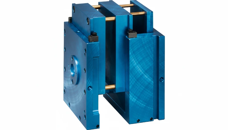
A MUD injection mold is a quick-change tooling system where one standardized mold base1 stays mounted in the injection molding machine. Instead of removing a full mold for each product change, the operator swaps a smaller insert that contains the cavity and core. This reduces setup time when several related parts share the same press, material family, and production window.
Think of it like a power drill: the drill itself stays in your hand, and you just swap the bit. The MUD frame is the drill; the insert mold2 is the bit. Standard frame sizes range from roughly 6 inches up to 18 inches, accommodating insert molds of various footprints. Each frame includes guide pins, bushings, and clamping mechanisms that align and lock the insert into position.
In our shop, we have used MUD-style frames for jobs that require multiple small parts in the same material family, such as connector housings, small covers, and sensor enclosures. The ability to swap inserts without pulling the entire mold from the press is a real time-saver when several SKUs run back to back. With 47 injection molding machines ranging from 90T to 1850T, we have the flexibility to dedicate certain presses for quick-change tooling setups like these. Our production team has the experience to handle fast insert swaps without sacrificing part quality or press uptime.
The key distinction from a standard mold is that the MUD frame handles all the infrastructure: alignment, ejection stroke, and press mounting. The insert focuses on part geometry. This separation is what drives both cost savings and faster tooling changes. You are not rebuilding the wheel every time you need a new part; you are just swapping the tire. That extra planning margin also protects sampling time.
How Does a MUD Quick-Change System Work?
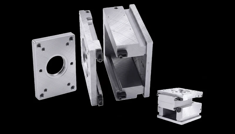
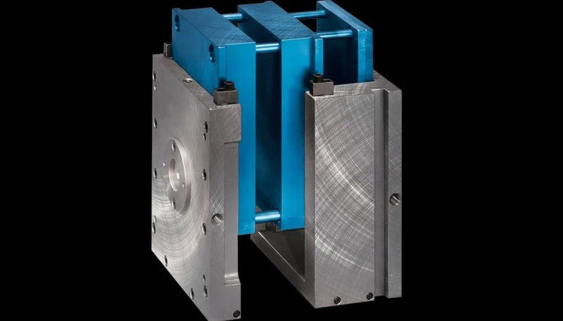
A mud quick-change system is a controlled process sequence that works through the stages and settings explained in this section. The MUD system has three main components: the master frame, the insert mold, and the locking mechanism. The master frame bolts into the press platens just like a conventional mold. It contains the ejector plate assembly, guide pin sets, support pillars, and a machined pocket sized to accept a specific class of insert.
The insert mold is a self-contained unit that holds the core, cavity, runner system, and its own cooling circuits. When you need to switch production from Part A to Part B, the operator opens the press, unclamps the current insert, slides it out, drops in the new insert, clamps it, and closes the mold. The whole process typically takes 10 to 30 minutes depending on the frame size and the complexity of the cooling and ejection hookup.
Some advanced MUD setups integrate quick-disconnect fittings for water lines and electrical connections, further reducing the swap time. Instead of manually wrenching individual coolant hoses on and off, the operator connects a single manifold block that routes cooling water to the correct channels inside the insert. These quick-disconnect fittings add upfront cost to the frame but pay for themselves quickly in a high-mix production environment where you might swap inserts three or four times per shift.
Compare that to a conventional mold change: you need to lower the mold from the press using a crane or forklift, disconnect all water lines and electrical connections, physically move a mold that can weigh hundreds of kilograms, then reverse the entire process for the new mold. That is two to four hours of downtime on a good day.
The locking mechanisms vary by manufacturer. DME’s original MUD system uses a wedge-style clamp that tightens from the side. Other systems use hydraulic clamps, toggle locks, or bayonet-style quick-release fittings. What matters for you as an engineer is understanding how the locking method affects insert alignment — misalignment of even a few thousandths of an inch will flash or produce out-of-tolerance parts.
In our production planning, MUD-style tooling is most useful when insert changes can run on compatible presses without long setup windows. ZetarMold has 20+ years of tooling experience and 47 injection molding machines from 90T to 1850T, so our engineers can match insert size, tonnage, material, and expected changeover frequency before recommending a MUD base.
When Should You Use a MUD System?
This section is about use a mud system and its impact on cost, quality, timing, or sourcing risk. MUD systems shine in specific scenarios. Here is where they genuinely add value, based on what we have seen running production molds over the past 20+ years. The common thread across all these use cases is that you need to run multiple different parts on the same press in relatively short production windows, and the cost of building dedicated full-size molds for each part cannot be justified by the volume.
Multi-Part Families in the Same Material
If you are molding a family of five small enclosures in ABS — same wall thickness, same gate style, same shrinkage — a MUD frame lets you run them all on one press with minimal changeover. This is the textbook use case. You mold SKU-1 for four hours, swap inserts, mold SKU-2 for three hours, and so on. One press, one frame, five inserts. The economics get even better when you factor in that each insert only needs maintenance on its own schedule — you do not take the entire frame offline to service one cavity.
Low-Volume and Prototype Production
When annual volumes are under 10,000 parts per SKU, building five dedicated full-size molds is hard to justify financially. Five MUD inserts at 40–60% of the cost of five full molds? That math works. We regularly recommend this approach to customers who need prototype bridges or market-test runs before committing to production tooling. The risk profile is also lower — if the product does not gain market traction, you are out a few thousand dollars per insert rather than tens of thousands per full mold.
Frequent Design Changes
During product development, when the design changes every few weeks, modifying a small insert is faster and cheaper than reworking a full mold base. The insert contains only the geometry-specific elements, so your modification cost is limited to the cavity and core steel, not the entire frame assembly. Our 8 senior engineers regularly work with customers on iterative insert designs during the validation phase.
There is also a scheduling advantage that people often overlook. If your production planner needs to squeeze in a small urgent job between two larger runs, a MUD insert lets you do that without disrupting the main schedule. You run the big job, pause for 20 minutes to swap in the urgent insert, run the short job, swap back, and resume. No crane, no recalibration of the press, no rebalancing the production floor.
What Are the Limitations of MUD Molds?
The limitations of mud molds are the main categories or options explained in this section. I would not be honest if I only talked about the benefits. MUD systems have real constraints that make them the wrong choice for many applications.
First, size limits. MUD inserts are small by design. Even the largest standard frames (15–18 inch series) limit your maximum part envelope. If your part is bigger than roughly 300mm in any dimension, or requires multiple cavities for high-volume output, a MUD system will not work. You need a full-size conventional mold.
Second, structural rigidity. A MUD insert sits in a pocket within the frame, and that interface is not as rigid as a solid one-piece mold. Under high injection pressures — especially with glass-filled materials — you may see parting line3 separation or flash at the insert-to-frame boundary. For tight-tolerance parts with ±0.05mm or stricter requirements, this flex can be a deal-breaker.
Third, cooling limitations. The insert mold has limited space for cooling channels compared to a full mold. Longer cycle time4 per shot is common, sometimes 15–25% longer than an equivalent conventional mold. If you are running millions of parts and every second of cycle time matters, the cooling penalty adds up fast.
Fourth, cavitation limits. Most MUD inserts accommodate 1 to 4 cavities. If your production plan calls for an 8-cavity or 16-cavity mold to hit volume targets, a MUD system cannot deliver. The insert footprint simply does not have room.
“A MUD insert mold costs 40–60% less than a full conventional mold for the same part.”True
The insert contains only the core, cavity, and basic cooling — no frame, no large ejector plate, no heavy support structures. The shared master frame amortizes across all inserts, so you save on steel, machining time, and engineering effort for each additional part design.
“MUD systems are ideal for high-volume production of large parts.”False
MUD inserts have strict size and cavitation limits. Large parts exceed the insert envelope, and high-volume jobs need multi-cavity layouts that do not fit. For large or high-volume production, conventional full-size molds remain the correct choice.
How Does MUD Compare to Conventional Mold Bases?
Here is a side-by-side comparison that reflects what we actually see in quoting and production, not theoretical textbook numbers.
| Factor | MUD Quick-Change | Conventional Mold |
|---|---|---|
| Initial mold cost (per part design) | 40–60% lower | Full price |
| Changeover time | 10–30 minutes | 2–4 hours |
| Max part size | ~300mm (largest frame) | Limited by press size only |
| Max cavitation | 1–4 cavities typical | 16+ cavities possible |
| Structural rigidity | Good (insert-in-frame) | Excellent (solid block) |
| Cycle time impact | +15–25% vs conventional | Baseline |
| Best for | Low-volume, multi-SKU, prototype | High-volume, large parts |
| Engineering change cost | Low (modify insert only) | High (modify full mold) |
The decision is not always binary. Some shops run both: conventional molds for their top-volume SKUs and a MUD frame on a dedicated press for the long tail of low-volume parts. With our monthly capacity of 100+ sets of injection molds, we build both styles regularly and can help you figure out which approach fits your specific product mix.
“Switching from conventional molds to a MUD system can reduce changeover downtime by over 90%.”True
A conventional mold change takes 2–4 hours (crane, disconnect water/electric, swap, reconnect, verify). A MUD insert swap takes 10–30 minutes (open press, unclamp, slide out, slide in, clamp, close). The difference is 90–95% less downtime per changeover.
“Any injection mold design can be converted to a MUD insert without trade-offs.”False
Insert size, cooling channel layout, ejection system complexity, and shot volume requirements all impose limits. Molds with complex side actions, lifters, or large undercuts may not fit within the insert envelope or maintain the required rigidity.
What Design Rules Apply to MUD Insert Molds?
Designing for a MUD system is not the same as designing a standalone injection mold. The insert has to work within the frame’s constraints. Here are the rules that matter most in practice.
1. Respect the insert envelope. Every frame size has a maximum pocket dimension. Your core and cavity must fit within that boundary with adequate wall thickness for structural support. Design the part first, then check it against the frame specs before committing to tooling. This sounds obvious, but I have seen engineers design a part, get approval, and then discover it does not fit any standard MUD insert.
2. Plan your gate location for the frame’s runner system. Most MUD frames have a standard injection mold design sprue location at center. If your part requires an edge gate or submarine gate, make sure the insert’s runner layout can deliver melt from that fixed sprue position to the optimal gate location on the part.
3. Minimize side actions. Slide mechanisms, lifters, and collapsed cores eat into the limited space inside an insert. Every side action adds complexity and reduces the space available for cooling channels. If your part has more than two external undercuts, a MUD insert becomes a very tight fit — and the tooling cost advantage starts to disappear.
4. Optimize cooling within the insert’s limits. You cannot run large-diameter cooling circuits through a compact insert. Use baffles, bubblers, or optimized channel layouts where possible to maximize heat extraction in the confined space. The cooling penalty is real, but good design can narrow the gap.
5. Verify ejection stroke against the frame’s ejector plate. The master frame provides the ejector plate and return system. Your insert needs to interface with it correctly — pin positions, stroke length, and return spring force all need to match. Most frames use a standard ejector pin grid pattern; design your insert’s ejection to align with that grid.
How Much Does a MUD Mold Cost Compared to Standard Tooling?
Cost is the reason most people consider MUD in the first place, so let me give you real numbers from our quoting experience. These are typical ranges for a single-cavity mold for a small electronic enclosure (approximately 80mm × 50mm × 25mm) in P20 steel.
| Cost Component | MUD Insert Only | Full Conventional Mold |
|---|---|---|
| Master frame (one-time) | $3,000–$6,000 | N/A (built into mold) |
| Insert mold (per part) | $2,500–$5,000 | $6,000–$12,000 |
| Additional inserts (each) | $2,500–$5,000 | $6,000–$12,000 |
| 5-part family total | $15,500–$31,000 | $30,000–$60,000 |
| Changeover labor per swap | 15 min × 1 operator | 3 hrs × 2 operators + crane |
| Production downtime per change | 10–30 min | 2–4 hrs |
The key insight: the master frame is a one-time investment. Once you own it, every additional insert is just the insert cost. For a five-part family, the MUD approach typically saves 40–50% on total tooling investment. For a ten-part family, the savings approach 55–60%.
But here is the catch people forget: if you are running one part design at very high volume — say 500,000+ parts per year — the cycle time penalty from limited cooling and the cavitation limits of a MUD insert mean your per-part cost is actually higher. The tooling savings get eaten by the production inefficiency. For that scenario, a dedicated 8-cavity conventional mold wins on total cost of ownership.
With our in-house mold steel sourcing and complete mold manufacturing facility (CNC machines, wire cutters, EDMs, grinders — 23 dedicated machines), we can deliver MUD inserts and conventional molds with competitive lead times. The key is choosing the right system for your production reality, not just the cheaper option.
-
mold base: A mold base refers to the standardized frame or housing that holds the core and cavity inserts, providing structural support, alignment features, and mounting interfaces for the injection molding machine platens. ↩
-
insert mold: An insert mold is a compact, self-contained mold unit that fits into a standardized mold base frame, containing only the core and cavity along with cooling and ejection components specific to one part design. ↩
-
parting line: The parting line refers to the visible seam on a molded part where the two halves of the mold meet, typically appearing as a slight ridge or line on the finished product surface. ↩
-
cycle time: Cycle time is defined as the total duration of one complete injection molding cycle, measured from mold close to mold close, including injection, packing, cooling, and ejection phases, typically expressed in seconds. ↩
Frequently Asked Questions About MUD Injection Molds
What does MUD stand for in injection molding?
MUD stands for Master Unit Die. It is a quick-change mold base system originally developed by DME (now part of Barnes Group) where a universal frame stays permanently mounted in the injection molding machine and small interchangeable insert molds slide in and out for rapid tooling changes. The master frame contains the ejector system, guide pins, and clamping mechanism, while each insert holds only the core, cavity, and its own cooling circuits. Although MUD is a registered trademark, the term has become widely used across the injection molding industry to describe any similar quick-change insert mold system regardless of manufacturer.
How long does a MUD insert changeover take?
A typical MUD insert changeover takes 10 to 30 minutes depending on the frame size and the complexity of cooling and ejection hookups. The operator opens the press, unclamps the current insert, slides it out, installs the new insert, clamps it, and closes the mold. This compares to 2–4 hours for a conventional full mold change that requires a crane or forklift, disconnecting water lines and electrical connections, physically moving a mold weighing hundreds of kilograms, and then reversing the entire process. For a production facility running multiple short-run jobs per day, this time saving is significant and directly translates to higher press utilization and lower per-part overhead costs.
What is the maximum part size for a MUD mold?
Maximum part size depends on the specific MUD frame series you select. The largest standard MUD frames available (typically the 15–18 inch series) can accommodate parts up to approximately 300mm in their largest dimension. However, you need to account for the insert wall thickness and structural support around the cavity, so the usable part envelope is somewhat smaller than the raw frame pocket dimension. Parts that exceed this size, or parts that require multi-cavity layouts to meet high-volume production targets, are better suited to conventional full-size molds where the only practical size limit is the tonnage and platen dimensions of your injection molding press.
Can a MUD system handle glass-filled or high-pressure materials?
MUD inserts can mold glass-filled and high-pressure materials, but you need to account for the structural limitations of the insert-to-frame interface. Because the insert sits in a pocket within the master frame rather than being a solid one-piece block, it is inherently less rigid under high injection pressures. With glass-filled nylons, PBT, or other high-viscosity engineering resins that require injection pressures above 150 MPa, you may see flash developing at the insert boundary or slight parting line separation. For tight-tolerance parts with ±0.05mm or stricter requirements molded in these aggressive materials, a conventional solid mold generally delivers more consistent dimensional stability across production runs.
How many cavities can fit in a MUD insert?
Most MUD inserts accommodate 1 to 4 cavities depending on the individual part size and the specific frame series being used. The compact insert footprint inherently limits the total number of cavities compared to conventional molds, which can be designed with 8, 16, or even 32 or more cavities for high-volume commodity parts. If your production volume requirements demand high cavitation to hit target cycle output and per-part cost, a conventional full-size mold will almost always be the more cost-effective choice over the life of the project, even though the initial tooling investment is higher.
Is a MUD mold suitable for medical or food-grade parts?
MUD inserts can produce medical and food-grade parts provided the insert is designed with appropriate surface finishes, adequate cooling for consistent material behavior, and proper ejection that does not contaminate the part surface. However, you should carefully consider the validation requirements. In regulated industries governed by FDA, ISO 13485, or similar frameworks, each insert may require its own qualification protocol including process validation, capability studies, and documentation. If you are running multiple inserts for a part family, the validation overhead for each individual insert can offset the tooling cost savings that make MUD attractive in the first place. For high-volume regulated parts, a dedicated conventional mold with a single comprehensive validation is often simpler.
What materials are MUD inserts typically made from?
MUD inserts are most commonly machined from P20 pre-hardened steel (approximately 28–32 HRC) for standard production runs, offering a good balance of machinability, polishability, and tool life at moderate cost. For high-wear applications involving glass-filled materials, abrasive engineering resins, or production runs exceeding 500,000 cycles, H13 hardened tool steel (48–52 HRC) provides significantly better wear resistance and thermal fatigue life. Aluminum inserts (typically 7075-T6) are also used for prototyping and very low-volume bridge runs where the lower material cost and faster CNC machining time outweigh the shorter tool life. S136 stainless steel is an option when corrosion resistance is required for PVC or other corrosive molding materials.


