 Zum Inhalt springen

- Tiefe Rippen (Tiefe > 25 mm)
- Draft angles of 1°–3° per side are essential for clean part ejection and long mold life.
- Rib height should not exceed 3× the adjoining wall thickness, and rib base should be 50–60% of wall thickness.
- Gate type and placement directly affect fill balance, weld-line location, and cosmetic quality.
- Early Moldflow-Analyse catches 80% of potential defects before steel is cut.
- Designing for manufacturability (DFM) up front saves 20–40% on tooling revisions.
Why Does Wall Thickness Matter Most in Injection Molding Design?
Wall thickness is the single most influential factor in injection molding product design because it controls fill behavior, cooling time, shrinkage, and structural integrity all at once. In our factory, we’ve seen more projects fail from inconsistent wall thickness than from any other design mistake.
The ideal wall thickness depends on the resin you choose. We always tell our clients: pick a thickness that allows complete fill without excessive cycle time. Here are the recommended ranges we use daily:
| Material | Recommended Wall Thickness (mm) | Max Flow Length-to-Thickness Ratio |
|---|---|---|
| ABS | 1.5 – 3.5 | 150:1 |
| Polypropylen (PP) | 1.0 – 3.0 | 250:1 |
| Polycarbonat (PC) | 1.5 – 4.0 | 100:1 |
| Nylon (PA6) | 1.0 – 3.5 | 150:1 |
| Polyethylen (PE) | 1.0 – 3.0 | 200:1 |
| POM (Acetal) | 1.5 – 3.5 | 120:1 |
When wall thickness varies by more than 15–20%, we see differential shrinkage that causes warpage. We’ve found that gradual transitions (3:1 taper ratio) between thick and thin sections reduce stress concentration by up to 50%. If you absolutely need thicker sections for strength, use ribs instead — they add rigidity without adding mass.
False: Thicker walls always make stronger parts.
True: Uniform wall thickness with strategic ribbing delivers better strength, shorter cycle times, and fewer defects than simply making walls thicker.
How Do Draft Angles Affect Part Ejection and Surface Quality?
Draft angles are the slight taper applied to vertical surfaces so the part releases cleanly from the mold. Without adequate draft, parts stick to the core, leading to scratches, distortion, or even broken ejector pins.
In our experience, the minimum draft we recommend is 1° per side for untextured surfaces. For textured surfaces, add an extra 1° for every 0.025 mm of texture depth. Here’s our quick-reference guide:
| Surface Condition | Minimum Draft Angle | Preferred Draft Angle |
|---|---|---|
| Untextured (polished) | 0.5° | 1° – 2° |
| Light texture (SPI B-3) | 1.5° | 2° – 3° |
| Medium texture (SPI C-3) | 3° | 3° – 5° |
| Heavy texture (SPI D-3) | 5° | 5° – 8° |
| Deep ribs (depth > 25 mm) | 1° | Eingeschlossene Luft |
We’ve found that clients sometimes resist adding draft because they want perfectly vertical walls. But even 0.5° makes a dramatic difference in ejection force. In one automotive housing project, increasing draft from 0.5° to 1.5° cut ejection-related scrap from 8% to under 1%.
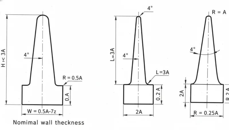
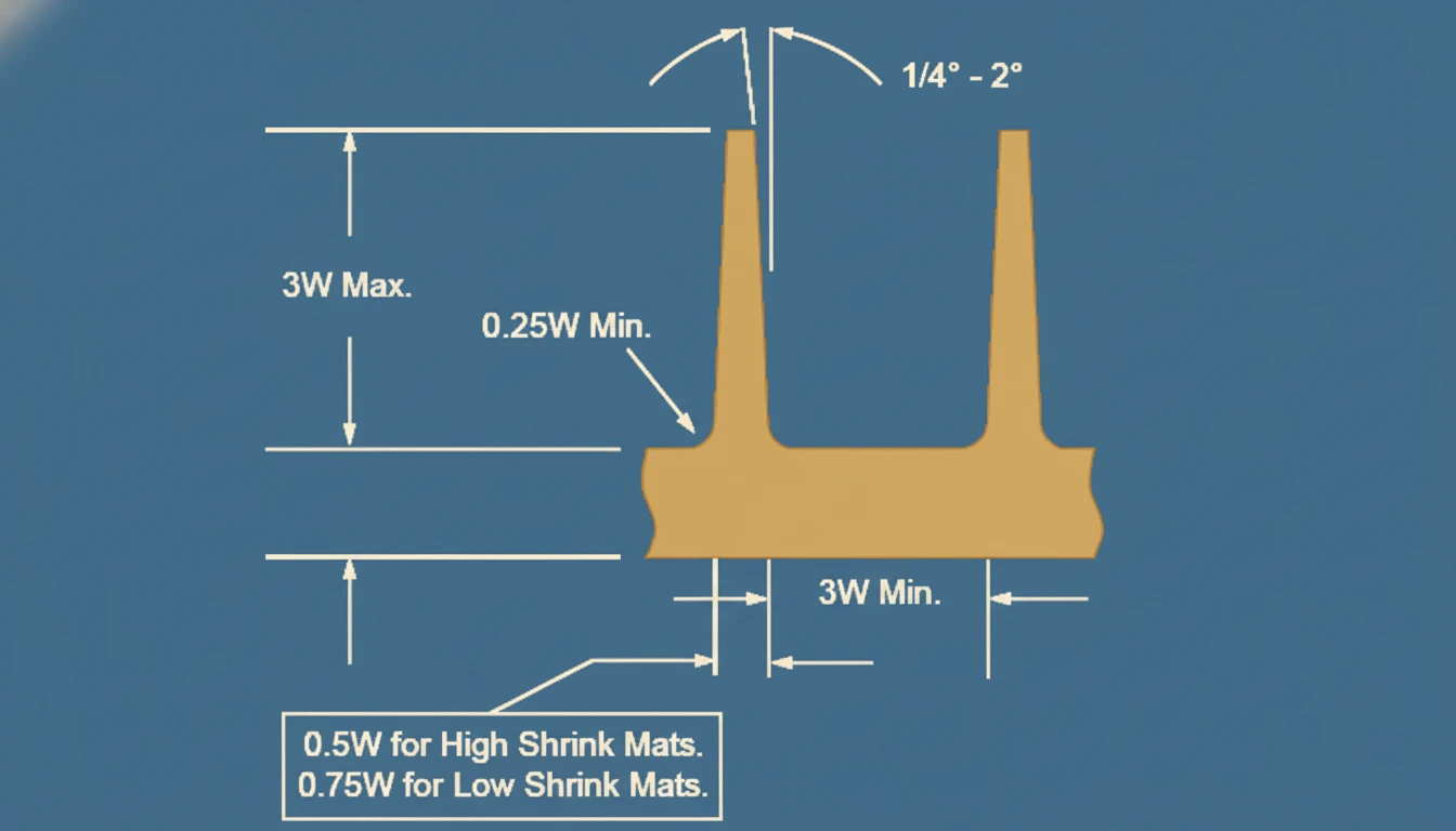
What Are the Best Practices for Rib and Boss Design?
Ribs and bosses are the structural backbone of injection molded parts. Ribs add stiffness without increasing wall thickness, while bosses provide mounting points for screws, inserts, and snap fits. The key rule we follow in our factory: rib base thickness should be 50–60% of the adjacent wall to avoid Einfallstellen on the cosmetic surface.
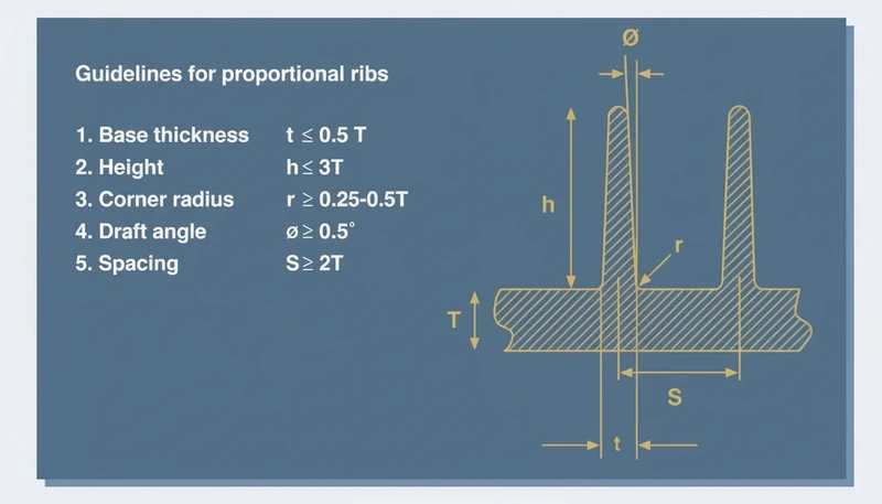
For ribs, we recommend:
- Height ≤ 3× wall thickness (taller ribs need extra draft or multiple shorter ribs)
- Base thickness = 50–60% of wall thickness
- Draft angle ≥ 0.5° per side (1° preferred)
- Spacing between ribs ≥ 2× wall thickness
- Fillet radius at base = 0.25–0.5× wall thickness
For bosses, the outer diameter should be about 2× the inner diameter, and the boss wall thickness should match or be slightly less than the nominal wall. We always connect bosses to nearby walls with gussets rather than leaving them freestanding, which reduces stress and improves fill.
How Should You Choose and Place Gates for Optimal Fill?
Gate selection and placement determine how resin flows into the cavity, where weld lines form, and how much cosmetic damage is acceptable. In our factory, we consider gate design one of the top three decisions that define part quality.
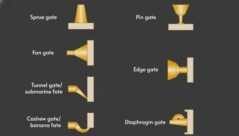
| Tor-Typ | Am besten für | Vestige | Auto-Trimming? |
|---|---|---|---|
| Edge gate | Flat, medium-sized parts | Visible on edge | Nein |
| Submarine (tunnel) gate | Automated production, small parts | Minimal | Yes |
| Pin gate (3-plate) | Multi-cavity, cosmetic parts | Small pin mark | Yes |
| Hot runner valve gate | Large parts, high-volume | Nearly invisible | Yes |
| Fan gate | Wide, flat parts | Visible on edge | Nein |
| Cashew gate | Hidden gate on cosmetic parts | Below parting line | Yes |
We always gate into the thickest section and let the melt flow from thick to thin. This ensures proper packing and minimizes sink. For multi-cavity molds, balanced runner systems are non-negotiable — we use Moldflow-Analyse to verify fill balance before cutting steel.
False: Gate location doesn’t matter as long as the cavity fills completely.
True: Gate location controls weld-line position, packing efficiency, and cosmetic appearance — it must be engineered, not guessed.
How Can You Avoid Common Defects Like Sink Marks and Warpage?
The most common injection molding defects — sink marks, warpage, weld lines, and short shots — are almost always traceable to product design decisions rather than process settings. In our experience, 70–80% of defects we troubleshoot on production floors could have been prevented at the design stage.
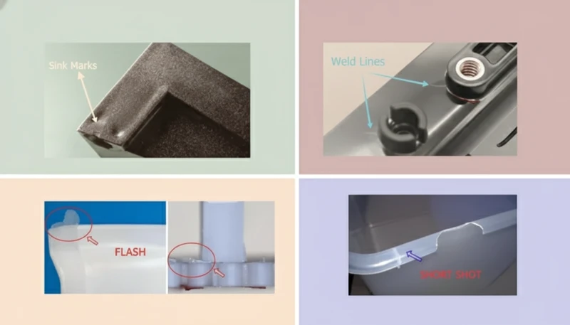
| Defekt | Verhindert Einfallstellen auf der gegenüberliegenden Oberfläche | Design Prevention |
|---|---|---|
| Sink marks | Thick sections, insufficient packing | Keep wall uniform; rib base ≤ 60% wall |
| Verzug | Uneven shrinkage, differential cooling | Uniform wall; symmetrical cooling channels |
| Schweißlinien | Flow fronts meeting | Relocate gate; increase wall at weld area |
| Short shots | Insufficient flow length | Increase wall thickness or add flow leaders |
| Blitzlicht | Excessive pressure, poor parting-line fit | Reduce projected area; optimize clamping force |
| Burn marks | Trapped air | Bereit, Ihr Produktdesign für das Spritzgießen zu validieren? |
We’ve found that running Moldflow-Analyse early catches most of these issues. It’s a relatively small investment (typically $500–$2,000 per part) that saves tens of thousands in mold rework.
What Role Does Material Selection Play in Product Design?
Material selection and product design are inseparable — the resin you choose dictates wall thickness ranges, shrinkage compensation, draft requirements, and achievable tolerances. We always urge clients to select material before finalizing geometry, not after.
| Material | Shrinkage Rate (%) | Key Design Consideration |
|---|---|---|
| ABS | 0.4 – 0.7 | Good for textured surfaces; moderate strength |
| PP | 1.0 – 2.5 | High shrinkage demands generous tolerances; living hinges possible |
| PC | 0.5 – 0.7 | Needs higher melt/mold temps; notch-sensitive |
| Simulation sagt Kühlleistung voraus | 0.8 – 1.5 (unfilled) | Hygroscopic — post-mold moisture absorption changes dimensions |
| POM | 1.8 – 2.5 | Very high shrinkage; tight tolerances difficult without glass fill |
| PC/ABS blend | 0.5 – 0.7 | Balanced properties; good for housings and enclosures |
When a client needs tight tolerances (±0.05 mm), we steer them toward low-shrinkage resins like ABS or PC. For parts requiring chemical resistance or flexibility, PP or TPE may be necessary, but the design must accommodate higher shrinkage and softer geometries.
How Does Design for Manufacturability (DFM) Save Time and Money?
DFM is the systematic approach of evaluating part geometry against manufacturing constraints before committing to tooling. In our factory, every project goes through a formal DFM review, and we consistently find that this step reduces mold revisions by 30–50% and cuts lead times by 1–3 weeks.
A proper DFM review covers:
- Parting line placement and its effect on cosmetics
- Draft adequacy on all surfaces
- Wall thickness uniformity
- Gate type, size, and location
- Ejector pin placement (avoiding cosmetic surfaces)
- Undercut feasibility (side actions, lifters, or redesign)
- Tolerance achievability for the chosen resin
- Cooling channel routing
We’ve worked on projects where skipping DFM led to $15,000–$30,000 in mold modifications after first samples. Conversely, a two-day DFM review costs our clients nothing extra — it’s included in our tooling service — and prevents exactly these costly surprises.
Häufig gestellte Fragen (FAQ)
What is the minimum wall thickness for injection molded parts?
For most engineering resins, the practical minimum is 0.8–1.0 mm for small parts and 1.5 mm for larger ones. Going thinner requires specialized thin-wall molding techniques with higher injection speeds and pressures. The minimum also depends on flow length — longer flow paths require thicker walls.
Can I have different wall thicknesses in the same part?
Yes, but transitions must be gradual. We recommend a 3:1 taper ratio (3 mm horizontal for every 1 mm vertical change). Abrupt thickness changes cause differential cooling, which leads to sink marks on the thick side and potential warpage across the entire part.
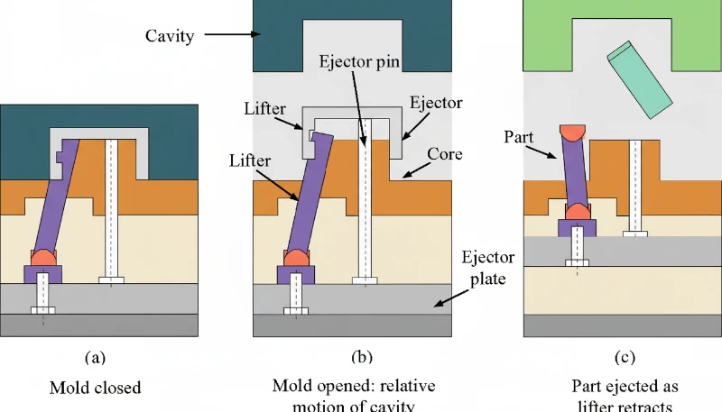
How do I know if my part needs a side action or lifter?
If your part has features (holes, slots, hooks) that are perpendicular to the mold opening direction and can’t be formed by the core/cavity alone, you’ll need a side action (for external features) or a lifter (for internal features). These add $2,000–$8,000 per action to mold cost, so we often suggest redesigning undercuts as snap-fit features or through-holes when possible.
What tolerances can injection molding achieve?
Standard commercial tolerances are ±0.1–0.2 mm for most dimensions. Fine tolerances of ±0.05 mm are achievable with low-shrinkage resins (ABS, PC) and precision molds. Critical mating dimensions should be called out on the drawing, and we’ll design the mold with tighter steel tolerances in those areas.
Should I use hot runners or cold runners?
Hot runners eliminate runner waste and reduce cycle time, but add $5,000–$20,000 to mold cost. We recommend hot runners for production volumes above 100,000 parts/year, multi-cavity molds (8+ cavities), or when material cost is high. For low-volume or prototyping, cold runners with efficient runner design are more cost-effective.
How early should I involve the mold maker in product design?
As early as possible — ideally during the concept phase. In our experience, the most successful projects involve mold maker input when the design is still at 60–70% completion. At this stage, changes are easy and free. After tooling starts, every design change multiplies in cost and delay.
Zusammenfassung
Designing for injection molding is fundamentally about understanding how molten plastic behaves inside a steel cavity. Every design decision — wall thickness, draft angles, ribs, gate placement, material selection — has a direct, measurable impact on part quality, cycle time, and tooling cost.
In our factory at ZetarMold, we’ve refined these principles across thousands of projects and 20+ years of mold making. The single most valuable piece of advice we offer: invest in DFM early. A few hours of engineering review before mold construction saves weeks of trial-and-error after. Whether you’re designing your first injection molded part or optimizing an existing one, these fundamentals remain constant.
Ready to validate your product design for injection molding? Contact ZetarMold for a free DFM review and quote.
Footnotes
- Tiefgangswinkel Wie man Spritzgussprodukte entwirft | Expertenleitfaden Learn more →
- Sink Mark — A localized surface depression that occurs when the inner material shrinks and pulls the outer skin inward, typically at thick sections, rib intersections, or boss locations. Learn more →
- Mold Flow Analysis — A computer simulation that predicts how molten plastic fills the cavity, where weld lines form, and how the part shrinks and warps. Used to optimize gate location, runner balance, and cooling layout before mold construction. Learn more →
- DFM (Design for Manufacturability) — A systematic engineering review that evaluates part geometry against injection molding constraints to identify potential issues before tooling begins. Learn more →
- TPE (Thermoplastic Elastomer) — A family of rubber-like materials that can be processed by injection molding. TPEs combine the flexibility of rubber with the recyclability and processing ease of thermoplastics. Learn more →


