 İçeriğe geç

- İnce Duvar Enjeksiyon Kalıplama İçin Hangi Malzemeler En İyi Şekilde Çalışır?
- Cycle times of 2–5 seconds are achievable — 5 to 10 times faster than conventional molding — making this process cost-effective for high-volume packaging and electronics.
- Material selection is critical: polypropylene (PP) with MFI of 40–60 g/10 min and ABS or PA66+GF high-flow grades dominate thin-wall applications.
- Tool steel grade (P20 for prototypes, H13 for production runs over 500,000 cycles) and conformal cooling channels directly determine part quality and tool life.
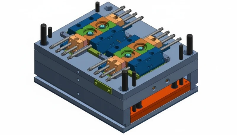
- ZetarMold runs 47 injection molding machines, including dedicated high-speed presses for thin-wall work, supporting customers from DFM review through mass production.
What Is Thin Wall Injection Molding?
İnce cidar enjeksiyon kalıplama1 500 ila 1.500 mm/s enjeksiyon hızlarında 1 mm'nin altında duvarlara sahip parçalar için bir imalat sürecidir. Bu makale, duvar kalınlığı bir milimetrenin altına düştüğünde başarıyı belirleyen parametreleri, malzemeleri, takımları ve kusur önleme stratejilerini kapsar.
Daha geniş bir bakış için, injection molding complete guide proses temellerini, malzeme davranışını ve üretim kararlarını kapsar.
For broader context, compare this topic with enjeksiyon kalıplama, enjeksiyon kalıbı2ve supplier sourcing kılavuz.
İnce cidarlı enjeksiyon kalıplama, duvar kesitleri 1.0 mm'nin altında — ve genellikle yüksek hacimli ambalajlama ve tüketici elektroniğinde 0.4 mm kadar ince — plastik parçalar üretmek için özel bir imalat sürecidir. Geleneksel kalıplamanın aksine, ince cidarlı iş, ince malzeme kalıpta donmadan önce tam boşluk dolumunu sağlamak için daha yüksek enjeksiyon hızları, yükseltilmiş dolum basınçları ve hassas takım gerektirir. Tasarım marjları dardır ve eriyik sıcaklığından kapı yerleşimine kadar her parametre, tutarlı parça Kalite3.

| Metrik | Thin-Wall | Conventional | Why It Matters |
|---|---|---|---|
| Duvar kalınlığı | <1.0 mm | 1.5–4.0 mm | Drives fill speed requirement |
| L/T ratio | >150:1 | <100:1 | Primary classification criterion |
| Enjeksiyon hızı | 500–1,500 mm/s | 50–200 mm/s | Must outrun freeze-off |
| Clamp force | 0.5–0.8 ton/cm2 | 0.3–0.5 ton/cm2 | Resists flash at high pressure |
In our factory at ZetarMold, we typically classify a part as thin-wall when any section falls below 0.8 mm or when the L/T ratio exceeds 200:1. At that threshold, conventional machines simply cannot fill the cavity — the material freezes off mid-flow and you get a short shot every time. The practical wall range for most consumer packaging is 0.5–0.9 mm; electronics and medical parts can push down to 0.3 mm with the right tool geometry.
The process is not just “regular injection molding with thinner walls.” It requires dedicated equipment with accumulators, a completely different gating strategy, tighter temperature control, and — critically — a mold design that accommodates the higher clamping force needed to resist flash at elevated pressures. Every element of the system must be engineered together.
How Does Thin Wall Injection Molding Work?
İnce cidarlı kalıplama, geleneksel enjeksiyon kalıplamaya benzer ancak aşırı parametrelerde çalışır ve boşluk dolumlarını 150 milisaniyenin altında tamamlar. Enjeksiyon aşaması, ince cidarlı işin geleneksel çalışmadan en keskin şekilde ayrıldığı yerdir; tamamen farklı bir makine özelliği ve hızlı dolum ve hassas termal kontrol etrafında inşa edilmiş bir takım stratejisi gerektirir.
Injection speed must reach 500–1,500 mm/s to fill the cavity before the melt front drops below the material’s no-flow temperature. For reference, conventional molding typically runs at 50–200 mm/s. The higher speed compresses the melt and generates significant shear heat, which helps offset the rapid heat loss to the cold mold wall. Timing is measured in milliseconds: a 0.5 mm wall part may fill in 0.05–0.10 seconds. On our high-speed presses, we monitor injection time in real time to detect any drift that might indicate a blocked vent or a gate that is beginning to wear.
| Phase | Thin-Wall Molding | Conventional Molding |
|---|---|---|
| Fill time | 0.05–0.15 s | 1–5 s |
| Hold time | 0.5–1.5 s | 3–10 s |
| Soğutma süresi | 2–4 s | 10–45 s |
| Total cycle | 2–5 s | 15–60 s |
Pack and hold pressure is applied immediately after fill to compensate for volumetric shrinkage as the part solidifies. In thin-wall work, the hold phase is short — typically 0.5–1.5 seconds — because the wall freezes rapidly and additional hold time does not improve density. Over-packing is a common mistake that causes flash and sticking. In our factory, we monitor the hold-to-fill transition using in-cavity pressure sensors, cutting hold the moment pressure stabilizes — usually within 0.8 seconds of fill completion.
Cooling is the dominant phase in terms of cycle time even in thin-wall molding. Because wall thickness is small, thermal diffusion is fast — 2–4 seconds of cooling is typically sufficient to reach ejection temperature. Conformal cooling channels that follow the cavity contour, rather than straight-drilled channels, reduce temperature variation across the part by 40–60% and allow 20–30% faster cycles. For a 0.6 mm PP container, well-designed conformal cooling delivers ejection-ready parts in under 2 seconds.
“Higher injection speed reduces short shots in thin-wall molding.”Doğru
In thin-wall parts, the melt front must reach all extremities of the cavity before the plastic solidifies. Raising injection speed from 200 mm/s to 800 mm/s reduces fill time by 75%, keeping the melt above the no-flow temperature throughout and eliminating the root cause of short shots in thin sections.
“You can use any standard injection machine for thin-wall parts.”Yanlış
Standard machines lack the accumulator-assisted injection unit needed to achieve 500–1,500 mm/s injection speeds, and their clamping systems are not designed for the high cavity pressures (140–250 MPa) required for thin walls. Using a conventional machine results in short shots, excessive flash, or machine damage.
What Are the Key Processing Parameters for Thin Wall Molding?
Thin-wall processing operates in narrow windows: any deviation from the optimal range immediately produces defects. The following parameters are the primary levers our process engineers adjust during qualification. A 5°C drop in melt temperature, a 10 MPa reduction in injection pressure, or a 2-second delay in cooling time can shift a part from acceptable to 100% scrap — tolerances that would be inconsequential in conventional 2 mm wall molding.
| Parametre | Thin-Wall Range | Conventional Range | Effect of Deviation |
|---|---|---|---|
| Enjeksiyon hızı | 500–1,500 mm/s | 50–200 mm/s | Too low → short shot; too high → flash or jetting |
| Enjeksiyon basıncı | 140–250 MPa | 70–140 MPa | Too low → short shot; too high → flash, excessive clamp |
| Erime sıcaklığı | 220–280°C (PP) | 200–260°C | Too high → degradation; too low → freeze-off |
| Kalıp sıcaklığı | 15–30°C (PP) | 20–60°C | Too high → cycle time increase; too low → warpage |
| Çevrim süresi | 2–5 s | 15–60 s | Too short → part not fully solid at ejection |
| Clamp force | 0.5–0.8 ton/cm2 | 0.3–0.5 ton/cm2 | Insufficient → flash at parting line |
Melt temperature control is especially critical because thin-wall sections cool 3–5 times faster than conventional parts. If melt temperature is 10°C below the recommended range, the outer skin freezes before the melt front reaches the last-fill zone, producing a short shot even at maximum injection speed. We set the barrel temperature profile so the nozzle zone is 5–10°C above the rear zone, maintaining consistent melt temperature at the gate and reducing fill inconsistency between shots.

İnce cidarlı takımlar için kapatma kuvveti hesaplaması, yüksek boşluk basınçlarını hesaba katmalıdır. İzdüşümlü alan × 0.3–0.5 ton/cm2 standart tahmini yetersizdir — ince cidarlı işler için 0.5–0.8 ton/cm2 kullanın. Yetersiz kapatılmış bir takım, enjeksiyon parametreleri doğru olsa bile ayırma çizgisinde taşma yapacaktır ve sadece taşmayı durdurmak için enjeksiyon basıncını düşürmek, parçayı kısa dolumlara itecektir.
| Parametre | Thin-Wall Requirement | Conventional Baseline | Key Rule |
|---|---|---|---|
| Clamp force | 0.5–0.8 ton/cm2 | 0.3–0.5 ton/cm2 | Calculate from projected area × 0.65 as starting point |
| Gate thickness | Match wall (0.6–0.8 mm) | 0.5–1.5 mm | Never smaller than wall thickness |
| Gate position | Thickest section | Anywhere balanced | Flow toward thin areas, not away |
| Vent depth | 0.015–0.025 mm | 0.02–0.04 mm | At last-fill points to prevent diesel effect |
Gate sizing is particularly critical in thin-wall tools. A gate that is too small restricts flow and elevates pressure drop; a gate that is too large causes jetting or weld-line defects. For walls under 0.8 mm, gate thickness should match or slightly exceed wall thickness — typically 0.6–0.8 mm — placed at the thickest section of the part to allow the melt front to progress toward thinner sections without premature freeze.
Venting is often underestimated. At 1,500 mm/s, trapped air in the cavity compresses faster than it can escape through normal parting line clearances. Dedicated vent slots (0.015–0.025 mm deep, 3–5 mm wide) at the last fill point prevent burn marks, short shots from air traps, and diesel effect — a flash-like defect caused by adiabatic compression igniting the resin.
Which Materials Work Best for Thin Wall Injection Molding?
Material selection for thin-wall parts is dominated by flow behavior. Resins must have a melt flow index high enough to fill the cavity before freeze-off, yet enough mechanical integrity after solidification to survive ejection without cracking. Standard resins used in conventional molding are frequently too viscous for thin-wall work.
Polipropilen (PP), baskın ince cidarlı reçinedir ve tüm ince cidarlı ambalaj üretiminin yaklaşık 'ını oluşturur. İdeal derece, 40–60 g/10 dak MFI'ye sahiptir (230°C/2.16 kg'da ölçülür). Yüksek MFI dereceleri 0.5 mm kesitlere kolayca akar ancak darbe direncinden ödün verebilir; formülatörler bunu çekirdeklendirici ajanlar ve darbe modifiye edicilerle dengeler. PP'nin düşük yoğunluğu (0.90–0.91 g/cm3) ayrıca parça ağırlığını azaltır, bu da ambalaj ekonomisinde kilit bir itici güçtür.
For structural and electronics applications, ABS high-flow grades (MFI 15–25 g/10 min at 220°C/10 kg) and PA66 reinforced with 15–30% glass fiber are preferred. The glass fiber increases stiffness significantly — from ~2.5 GPa for unfilled PA66 to 6–8 GPa for PA66+30%GF — allowing thinner walls while maintaining the structural performance required for connector housings, brackets, and enclosure panels.
| Malzeme | MFI (g/10 min) | Min Wall (mm) | Best Applications | Key Limitation |
|---|---|---|---|---|
| PP (high-flow) | 40–60 | 0.4 | Packaging, caps, containers | Lower stiffness than engineering resins |
| ABS (high-flow) | 15–25 | 0.6 | Electronics housings, toys | Limited chemical resistance |
| PA66+GF15% | 10–20 | 0.5 | Connector housings, brackets | Moisture absorption, higher cost |
| HDPE (high-flow) | 20–40 | 0.5 | Caps, food-grade packaging | Low stiffness, prone to warpage |
| LDPE / LLDPE | 15–30 | 0.4 | Flexible lids, closures | Not suitable for rigid structures |
One material decision point that surprises many buyers: using the same resin grade as in your conventional tools will likely not work in a thin-wall tool. We frequently see customers bring a PP grade with MFI 12 g/10 min that runs perfectly in a 2 mm wall part but causes 100% short shots in a 0.7 mm wall tool. Resin qualification is a mandatory step, not an afterthought — budget one to two weeks for material trials before tool sign-off.
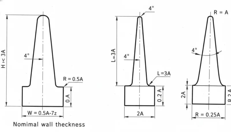
How Should You Design a Mold for Thin Wall Parts?
İnce cidarlı bir kalıp, beş kritik tasarım alanı ile tanımlanır: kapı geometrisi, uyumlu soğutma, havalandırma, çıkarma stratejisi ve çelik seçimi. Bunlardan herhangi birinde hata yapmak, ya kusurlu bir parça, kırık bir takım ya da kabul edilemez derecede uzun bir döngü süresi üretecektir.
Gate design drives fill balance and weld line location. For rectangular thin-wall parts like food containers, a film gate running along the full width of one edge gives the most uniform fill front and eliminates weld lines entirely. Fan gates work well for smaller parts. Point gates (hot or cold) at the thickest feature — typically a boss or rib — direct the melt toward thinner areas, but require careful simulation to avoid weld lines at visible surfaces.
| Cilt | Recommended Steel | Sertlik | Cost vs. P20 |
|---|---|---|---|
| <50,000 shots | Aluminum (QC-10) | N/A | Tıbbi tek kullanımlık ürünler — şırınga gövdesi, pipet uçları, tanı kartuşları ve mikroakışkan çipler — hem ince duvarlar (0.3–0.7 mm) hem de biyouyumlu malzemeler (USP Sınıf VI sertifikalı reçineler) gerektirir. Temiz oda üretimi ve doğrulanmış süreçler (IQ/OQ/PQ kalifikasyon protokolleri) maliyeti artırır ancak düzenlenmiş pazarlar için pazarlık konusu değildir. Otomotiv iç mekan parçaları (klips yuvaları, konnektör braketleri, kapı paneli ekleri) tabloyu tamamlar, motor bölmesi ve 140°C'ye kadar kabin ortamlarında gerekli olan yapısal sertlik için yüksek cam elyaf içeriğine sahip PA veya PBT gerektirir. |
| 100,000–500,000 shots | P20 pre-hardened | 30–36 HRC | Baseline |
| >1,000,000 shots | H13 hot-work tool steel | 48–52 HRC | 15–25% more |
| >5,000,000 shots | H13 + PVD coating | 58–62 HRC surface | 25–40% more |
Steel selection is determined by production volume. For prototype runs under 50,000 shots, aluminum (Alcoa QC-10 or equivalent) machines faster and costs 30–50% less than steel tooling. For production volumes of 100,000–500,000 shots, P20 pre-hardened steel (30–36 HRC) is the workhorse choice. For high-volume runs exceeding 1,000,000 shots — typical in packaging — H13 hot-work tool steel hardened to 48–52 HRC is required. H13 resists the higher contact stress from elevated cavity pressures and maintains dimensional accuracy over millions of cycles.
“Conformal cooling channels are worth the added mold cost for thin-wall production.”Doğru
Conformal cooling channels follow the cavity contour, reducing temperature variation from ±15°C to ±5°C and enabling 20–30% faster cycles. At 10 million shots per year on a packaging line, a 20% cycle time reduction translates to 2 million additional parts annually — easily justifying the 15–25% higher mold cost.
“Standard mold steel P20 is sufficient for all thin-wall production volumes.”Yanlış
P20 (30–36 HRC) is adequate for prototype and medium-volume work up to approximately 500,000 shots. Above that threshold, the elevated cavity pressures in thin-wall molding (up to 250 MPa) cause accelerated wear and dimensional drift. H13 at 48–52 HRC is required for high-volume production to maintain gate and cavity dimensions through millions of cycles.
What Are the Common Defects in Thin Wall Injection Molding and How to Prevent Them?
Thin-wall parts are highly sensitive to process variation. The same root cause that produces a barely acceptable part at nominal conditions creates a 100% defect rate when one parameter drifts by 10%. Understanding the specific failure modes allows engineers to set tight process alarm limits and prevent downtime. In our quality system at ZetarMold, all thin-wall tools are fitted with cavity pressure sensors that trigger automatic part rejection when peak pressure deviates more than ±5% from the nominal value — catching short shots and flash before they reach the quality inspection stage.
The following table summarizes the seven most common defects we encounter on thin-wall tools, along with their root causes and the corrective actions that reliably fix them. Note that several defects share symptoms but require opposite interventions — correctly identifying the root cause before adjusting parameters saves significant troubleshooting time.
| Kusur | Karşı yüzeyde çökme izlerini önler | Prevention |
|---|---|---|
| Kısa atış | Insufficient speed/pressure; freeze-off before fill complete | Increase injection speed; optimize gate size; increase melt temp |
| Flaş | Excessive injection pressure; insufficient clamp force; worn parting line | Reduce pack pressure; verify clamp tonnage; inspect parting line |
| Çarpıklık | Non-uniform cooling; unbalanced flow; residual stress | Conformal cooling; balanced runner; symmetrical gate placement |
| Sink marks | Insufficient pack pressure; premature gate freeze | İnce duvarlı gıda ambalajı kabı |
| Kaynak hatları | Multiple flow fronts meeting without sufficient heat | Relocate gate; increase melt temperature; reduce wall variation |
| Burn marks | Trapped air; excessive injection speed in end-fill zone | Add venting at last-fill locations; reduce speed in final 5–10% of fill |
| Jetting | Gate too small; high injection speed with poor gate design | Use film or fan gate; increase gate diameter; reduce injection speed at gate |
“Identifying the root cause of a defect before adjusting process parameters is essential in thin-wall troubleshooting.”Doğru
Several thin-wall defects share visible symptoms but require opposite corrective actions. Weld lines and sink marks can both appear as surface depressions — increasing pack pressure addresses a sink mark but does nothing for a weld line’s root cause (gate location and melt temperature). Similarly, flash and short shots are caused by opposite conditions: excess pressure vs. insufficient pressure. Misdiagnosing the defect and adjusting in the wrong direction typically makes the problem worse, wastes machine time, and can damage tooling.
“The same process settings can be used for thin-wall injection molding across packaging, electronics, and medical applications.”Yanlış
Each application segment requires fundamentally different process parameters and quality requirements. Packaging optimizes for maximum throughput and minimum material cost (simple QC, FDA resin compliance). Electronics demands Class A surface quality with tight dimensional tolerances (±0.1 mm). Medical applications require IQ/OQ/PQ process validation, clean-room production, and biocompatible resins (USP Class VI). Automotive parts need PPAP qualification and IATF 16949 controls. A single process window does not serve all these segments — material selection, validation protocols, and QC rigor differ substantially.
In our production experience at ZetarMold, the most frequently misdiagnosed thin-wall defect is a weld line mistaken for a sink mark. A weld line appears as a visible seam on the surface, often with a slight depression. Operators sometimes increase pack pressure, which fixes the depth but not the seam visibility. The real fix is to reposition the gate so both flow fronts merge at a non-visible surface, or to run a mold flow analysis simulation before the tool is cut to predict and eliminate weld line locations during the design phase rather than after production has started.
Controlling Flash in Thin-Wall Tools
Taşma önleme sistematik bir yaklaşım gerektirir. Enjeksiyon parametrelerini ayarlamanın ötesinde, kapatma tonajının doğru hesaplandığını doğrulamanız gerekir — ince cidarlı parçalar için, geleneksel 0.3–0.5 ton/cm2 yerine boşluğun izdüşümlü alanının 0.5–0.8 ton/cm2 ile çarpımını kullanın. Yetersiz kapatılmış ince cidarlı takımlar düşük dolum basıncında taşar; düzgün dolum için basıncı artırmak sadece taşmayı kötüleştirir. Bir takım düşük dolum basıncında bile sürekli taşıyorsa, başka herhangi bir parametreyi ayarlamadan önce önce kapatma kuvveti hesaplamasını kontrol edin. Plakadaki dijital bir kapatma kuvveti göstergesi, gerçek zamanlı geri bildirim sağlar ve çoğu taşma kusuruna neden olan tahmin işinden kaçınmanıza yardımcı olur.
Where Is Thin Wall Injection Molding Used?
İnce duvarlı enjeksiyon kalıplama, gıda ambalajlama, elektronik, tıbbi, otomotiv ve kapaklarda hafif parçalar için baskın işlemdir. Her segmentin, doğrudan etkileyen farklı duvar kalınlığı gereksinimleri, malzeme özellikleri, kalite standartları ve üretim ölçeği gereksinimleri vardır alet tasarımı ve süreç kontrol stratejileri.
| Endüstri | Typical Wall (mm) | Key Material | Volume/Year |
|---|---|---|---|
| Food & beverage packaging | 0.5–0.8 | PP (FDA grade) | Billions of units |
| Tüketici elektroniği | 0.8–1.2 | ABS / PC-ABS | Hundreds of millions |
| Medical disposables | 0.3–0.7 | PP / PE (USP VI) | Billions of units |
| Automotive interior | 1.0–1.5 | PA+GF / PBT | Tens of millions |
| Industrial caps & closures | 0.6–1.0 | PP / HDPE | Billions of units |
Market-Specific Requirements at a Glance
Food and beverage packaging accounts for the largest volume by far. PP thin-wall containers for yogurt, deli items, and ready meals are produced at very high rates of 10,000–50,000 cycles per day per cavity. Wall thickness is typically 0.5–0.8 mm. FDA-compliant PP grades meeting 21 CFR requirements are standard; no heavy metal stabilizers, no BPA. The economics are compelling: a 0.6 mm wall container uses 25–30% less material than a 0.9 mm wall equivalent.
Consumer electronics enclosures represent the second-largest thin-wall segment. Smartphone housings, laptop palms, and tablet backs require walls of 0.8–1.2 mm in ABS or PC/ABS blends to achieve Class A surface quality with embedded snap features and living hinges. Dimensional tolerances are tight — typically ±0.1 mm — and surface finish must be free of flow marks, which demands careful gate placement and mold flow simulation before tooling. Post-mold operations including pad printing, ultrasonic welding, and surface coating require part-to-part consistency that thin-wall processes deliver when properly validated.
| Segment | Key Standard | Critical Requirement |
|---|---|---|
| Gıda ambalajları | FDA 21 CFR | Resin compliance, no BPA |
| Tıbbi cihazlar | USP Sınıf VI / ISO 10993 | Biocompatibility, process validation |
| Otomotiv | IATF 16949 | PPAP, Cpk ≥1.67 |
| Elektronik | RoHS / REACH | Halogen-free materials |
At our Shanghai factory, we run 47 injection molding machines from 90T to 1850T, including dedicated high-speed presses for thin-wall production. With experience across 400+ plastic materials, we support customers from DFM review through mass production of thin-wall parts — from 0.3 mm medical disposables to high-volume PP packaging running at 15,000 shots per hour.
Medical disposables — syringe barrels, pipette tips, diagnostic cartridges, and microfluidic chips — require both thin walls (0.3–0.7 mm) and biocompatible materials (USP Class VI certified resins). Clean-room production and validated processes (IQ/OQ/PQ qualification protocols) add cost but are non-negotiable for regulated markets. Automotive interior parts (clip housings, connector brackets, door panel inserts) complete the picture, demanding PA or PBT with high glass fiber content for the structural rigidity required in underhood and cabin environments up to 140°C.
Frequently Asked Questions About Thin Wall Injection Molding?
Sıkça Sorulan Sorular
What wall thickness qualifies as ‘thin wall’ in injection molding?
A part is classified as thin-wall when any cross-section is below 1.0 mm with a flow-length-to-thickness (L/T) ratio above 150:1. In practice, most packaging applications fall in the 0.5–0.8 mm range. Parts with walls of 1.0–1.5 mm and high L/T ratios (150:1–200:1) occupy a transitional zone that requires some thin-wall process adjustments but not necessarily dedicated thin-wall equipment. The L/T ratio is the more reliable classification criterion: a long, slender 1.2 mm section can behave like a true thin-wall part during fill.
How fast is thin wall injection molding compared to standard molding?
Cycle times for thin-wall parts are typically 2–5 seconds, compared to 15–60 seconds for conventional injection molding — a 5–10× speed advantage. This is driven by rapid heat dissipation from thin cross-sections, which cuts cooling time dramatically. At ZetarMold, high-volume thin-wall packaging runs at 12,000–15,000 shots per hour on multi-cavity tools, producing over 100,000 finished parts per hour on a 16-cavity tool. On an annual basis, this speed advantage translates directly to lower per-part cost and faster response to demand spikes.
What injection pressure is required for thin wall parts?
Thin-wall injection molding requires injection pressure of 140–250 MPa, compared to 70–140 MPa for conventional molding. The elevated pressure is necessary to drive high-flow-rate melt into very thin cavities before freeze-off occurs. Machines must be equipped with accumulators or servo-driven injection units to achieve the rapid pressure buildup required — conventional hydraulic machines cannot respond fast enough. Cavity pressure sensors are strongly recommended to monitor and control the actual pressure inside the mold, not just the hydraulic pressure at the machine.
Can I use my existing injection molding machine for thin wall parts?
Usually not without significant upgrades. Standard machines lack the accumulator-assisted injection unit needed to achieve 500–1,500 mm/s injection speeds. The injection unit response time on a conventional machine is too slow — by the time full pressure builds, the thin section has already started to freeze. Dedicated thin-wall presses from Husky, Netstal, or Engel with servo-electric or accumulator-hydraulic systems are required for consistent production. Some processors retrofit an accumulator to an existing machine, which can work if the injection speed and response time are verified post-retrofit.
What is the minimum wall thickness achievable with injection molding?
Üretim enjeksiyon kalıplamada elde edilebilen minimum duvar kalınlığı, yerel ısıtmalı hassas kalıplarda yüksek akışlı PP veya LCP reçineleri kullanılarak yaklaşık 0.3 mm'dir. 0.5–0.6 mm duvarlar, bir dizi malzeme arasında daha rutin olarak elde edilebilir. Minimum duvar kalınlığını sınırlayan faktörler arasında dolum sıcaklığındaki malzeme viskozitesi, kapıdan son dolum noktasına olan mesafe (akış uzunluğu), kalıp sıcaklığı düzgünlüğü ve mevcut enjeksiyon basıncı bulunur. 0.3 mm'nin altında, boyutsal tutarlılığı korumak için özel ekipmanlar — 1 cm3'ün altında namlu hacimleri, hassas vidalar — ile mikro-enjeksiyon kalıplama gereklidir.
Does thin wall injection molding require special mold steel?
Yes. For prototype and low-volume work under 50,000 shots, aluminum tooling (Alcoa QC-10 or equivalent) is cost-effective and machines faster. For medium production runs of 100,000–500,000 shots, P20 pre-hardened steel (30–36 HRC) is the standard choice. For high-volume production above 1,000,000 shots — typical in packaging — H13 hot-work tool steel hardened to 48–52 HRC is required to resist the higher cavity pressures up to 250 MPa and maintain dimensional accuracy over millions of cycles without gate wear or cavity distortion.
-
enjeksiyon kalıplama: enjeksiyon kalıplama, plastiği eriten, bir kalıp boşluğuna enjekte eden, parçayı soğutan ve kararlı hacimli üretim için döngüyü tekrarlayan üretim sürecini ifade eder. ↩
-
enjeksiyon kalıbı: enjeksiyon kalıbı, parça geometrisini, soğutma davranışını, çıkarmayı, kapılamayı, yüzey bitirmesini ve tekrarlanabilirliği tanımlayan hassas takımdır. ↩
-
Kalite: Kalite, TÜT, kalıp doğrulama, proses pencereleri, muayene planları ve düzeltici eylemi tekrarlanabilir çıktıya bağlayan bir üretim disiplinidir. ↩


