 Vai al contenuto

- Insufficiente → flash alla linea di separazione
- Cycle times of 2–5 seconds are achievable — 5 to 10 times faster than conventional molding — making this process cost-effective for high-volume packaging and electronics.
- Material selection is critical: polypropylene (PP) with MFI of 40–60 g/10 min and ABS or PA66+GF high-flow grades dominate thin-wall applications.
- Tool steel grade (P20 for prototypes, H13 for production runs over 500,000 cycles) and conformal cooling channels directly determine part quality and tool life.
- ZetarMold runs 47 injection molding machines, including dedicated high-speed presses for thin-wall work, supporting customers from DFM review through mass production.
What Is Thin Wall Injection Molding?
Parete sottile stampaggio a iniezione1 è un processo di produzione per pezzi con pareti inferiori a 1 mm a velocità di iniezione da 500 a 1.500 mm/s. Questo articolo tratta i parametri, i materiali, gli stampi e le strategie di prevenzione dei difetti che determinano il successo quando lo spessore della parete scende sotto il millimetro.
Per una visione più ampia, i nostri guida completa allo stampaggio a iniezione copre i fondamenti del processo, il comportamento dei materiali e le decisioni produttive.
For broader context, compare this topic with stampaggio a iniezione, stampo a iniezione2, e supplier sourcing guida.
Lo stampaggio a iniezione a pareti sottili è un processo di produzione specializzato per produrre pezzi in plastica con sezioni di parete inferiori a 1,0 mm — e spesso fino a 0,4 mm negli imballaggi ad alto volume e nell'elettronica di consumo. A differenza dello stampaggio convenzionale, il lavoro a pareti sottili richiede velocità di iniezione più elevate, pressioni di mantenimento elevate e stampi di precisione per ottenere un riempimento completo della cavità prima che il materiale sottile si solidifichi nello stampo. I margini di progettazione sono stretti e ogni parametro, dalla temperatura del fuso al posizionamento del punto di iniezione, diventa critico per ottenere un pezzo qualità3.

| Metrico | Thin-Wall | Conventional | Why It Matters |
|---|---|---|---|
| Spessore della parete | <1.0 mm | 1.5–4.0 mm | Drives fill speed requirement |
| L/T ratio | >150:1 | <100:1 | Primary classification criterion |
| Velocità di iniezione | 500–1,500 mm/s | 50–200 mm/s | Must outrun freeze-off |
| Clamp force | 0,5–0,8 ton/cm2 | 0,3–0,5 ton/cm2 | Resists flash at high pressure |
In our factory at ZetarMold, we typically classify a part as thin-wall when any section falls below 0.8 mm or when the L/T ratio exceeds 200:1. At that threshold, conventional machines simply cannot fill the cavity — the material freezes off mid-flow and you get a short shot every time. The practical wall range for most consumer packaging is 0.5–0.9 mm; electronics and medical parts can push down to 0.3 mm with the right tool geometry.
The process is not just “regular injection molding with thinner walls.” It requires dedicated equipment with accumulators, a completely different gating strategy, tighter temperature control, and — critically — a mold design that accommodates the higher clamping force needed to resist flash at elevated pressures. Every element of the system must be engineered together.
How Does Thin Wall Injection Molding Work?
Lo stampaggio a pareti sottili è simile allo stampaggio a iniezione convenzionale ma funziona con parametri estremi, completando il riempimento della cavità in meno di 150 millisecondi. La fase di iniezione è dove il lavoro a pareti sottili diverge più nettamente da quello convenzionale, richiedendo una specifica della macchina completamente diversa e una strategia di costruzione dello stampo basata su riempimento rapido e controllo termico preciso.
Injection speed must reach 500–1,500 mm/s to fill the cavity before the melt front drops below the material’s no-flow temperature. For reference, conventional molding typically runs at 50–200 mm/s. The higher speed compresses the melt and generates significant shear heat, which helps offset the rapid heat loss to the cold mold wall. Timing is measured in milliseconds: a 0.5 mm wall part may fill in 0.05–0.10 seconds. On our high-speed presses, we monitor injection time in real time to detect any drift that might indicate a blocked vent or a gate that is beginning to wear.
| Phase | Thin-Wall Molding | Conventional Molding |
|---|---|---|
| Come Scegliere la Velocità di Iniezione Giusta per lo Stampaggio | 0.05–0.15 s | 1–5 s |
| Hold time | 0.5–1.5 s | 3–10 s |
| Tempo di raffreddamento | 2–4 s | 10–45 s |
| Total cycle | 2–5 s | 15–60 s |
Pack and hold pressure is applied immediately after fill to compensate for volumetric shrinkage as the part solidifies. In thin-wall work, the hold phase is short — typically 0.5–1.5 seconds — because the wall freezes rapidly and additional hold time does not improve density. Over-packing is a common mistake that causes flash and sticking. In our factory, we monitor the hold-to-fill transition using in-cavity pressure sensors, cutting hold the moment pressure stabilizes — usually within 0.8 seconds of fill completion.
Cooling is the dominant phase in terms of cycle time even in thin-wall molding. Because wall thickness is small, thermal diffusion is fast — 2–4 seconds of cooling is typically sufficient to reach ejection temperature. Conformal cooling channels that follow the cavity contour, rather than straight-drilled channels, reduce temperature variation across the part by 40–60% and allow 20–30% faster cycles. For a 0.6 mm PP container, well-designed conformal cooling delivers ejection-ready parts in under 2 seconds.
“Higher injection speed reduces short shots in thin-wall molding.”Vero
In thin-wall parts, the melt front must reach all extremities of the cavity before the plastic solidifies. Raising injection speed from 200 mm/s to 800 mm/s reduces fill time by 75%, keeping the melt above the no-flow temperature throughout and eliminating the root cause of short shots in thin sections.
“You can use any standard injection machine for thin-wall parts.”Falso
Standard machines lack the accumulator-assisted injection unit needed to achieve 500–1,500 mm/s injection speeds, and their clamping systems are not designed for the high cavity pressures (140–250 MPa) required for thin walls. Using a conventional machine results in short shots, excessive flash, or machine damage.
What Are the Key Processing Parameters for Thin Wall Molding?
Thin-wall processing operates in narrow windows: any deviation from the optimal range immediately produces defects. The following parameters are the primary levers our process engineers adjust during qualification. A 5°C drop in melt temperature, a 10 MPa reduction in injection pressure, or a 2-second delay in cooling time can shift a part from acceptable to 100% scrap — tolerances that would be inconsequential in conventional 2 mm wall molding.
| Parametro | Thin-Wall Range | Conventional Range | Effect of Deviation |
|---|---|---|---|
| Velocità di iniezione | 500–1,500 mm/s | 50–200 mm/s | Too low → short shot; too high → flash or jetting |
| Pressione di iniezione | 140–250 MPa | 70–140 MPa | Too low → short shot; too high → flash, excessive clamp |
| Temperatura di fusione | 220–280°C (PP) | 200–260°C | Too high → degradation; too low → freeze-off |
| Temperatura dello stampo | 15–30°C (PP) | 20–60°C | Too high → cycle time increase; too low → warpage |
| Tempo di ciclo | 2–5 s | 15–60 s | Too short → part not fully solid at ejection |
| Clamp force | 0,5–0,8 ton/cm2 | 0,3–0,5 ton/cm2 | Insufficient → flash at parting line |
Raffreddamento non uniforme; flusso sbilanciato; stress residuo

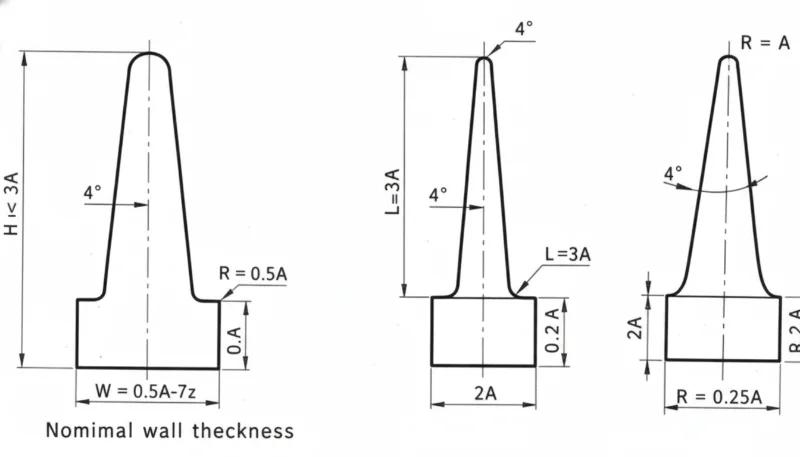
Il calcolo della forza di chiusura per gli stampi a pareti sottili deve tenere conto delle elevate pressioni in cavità. La stima standard di area proiettata × 0,3–0,5 ton/cm2 è insufficiente — utilizzare 0,5–0,8 ton/cm2 per il lavoro a pareti sottili. Uno stampo sottodimensionato in chiusura presenterà sfrido sulla linea di separazione anche quando i parametri di iniezione sono corretti, e semplicemente ridurre la pressione di iniezione per fermare lo sfrido porterà il pezzo a difetti da mancato riempimento.
| Parametro | Thin-Wall Requirement | Conventional Baseline | Key Rule |
|---|---|---|---|
| Clamp force | 0,5–0,8 ton/cm2 | 0,3–0,5 ton/cm2 | Calculate from projected area × 0.65 as starting point |
| Gate thickness | Match wall (0.6–0.8 mm) | 0.5–1.5 mm | Never smaller than wall thickness |
| Gate position | Thickest section | Anywhere balanced | Flow toward thin areas, not away |
| Vent depth | 0.015–0.025 mm | 0.02–0.04 mm | At last-fill points to prevent diesel effect |
Gate sizing is particularly critical in thin-wall tools. A gate that is too small restricts flow and elevates pressure drop; a gate that is too large causes jetting or weld-line defects. For walls under 0.8 mm, gate thickness should match or slightly exceed wall thickness — typically 0.6–0.8 mm — placed at the thickest section of the part to allow the melt front to progress toward thinner sections without premature freeze.
Venting is often underestimated. At 1,500 mm/s, trapped air in the cavity compresses faster than it can escape through normal parting line clearances. Dedicated vent slots (0.015–0.025 mm deep, 3–5 mm wide) at the last fill point prevent burn marks, short shots from air traps, and diesel effect — a flash-like defect caused by adiabatic compression igniting the resin.
Which Materials Work Best for Thin Wall Injection Molding?
Material selection for thin-wall parts is dominated by flow behavior. Resins must have a melt flow index high enough to fill the cavity before freeze-off, yet enough mechanical integrity after solidification to survive ejection without cracking. Standard resins used in conventional molding are frequently too viscous for thin-wall work.
Il polipropilene (PP) è la resina dominante per pareti sottili, rappresentando circa il 60% di tutta la produzione di imballaggi a pareti sottili. Il grado ideale ha un MFI di 40–60 g/10 min (misurato a 230°C/2,16 kg). I gradi ad alto MFI scorrono facilmente in sezioni di 0,5 mm ma possono sacrificare la resistenza all'impatto; i formulatori bilanciano questo con agenti nucleanti e modificatori d'impatto. La bassa densità del PP (0,90–0,91 g/cm3) riduce anche il peso del pezzo, un fattore chiave nell'economia degli imballaggi.
For structural and electronics applications, ABS high-flow grades (MFI 15–25 g/10 min at 220°C/10 kg) and PA66 reinforced with 15–30% glass fiber are preferred. The glass fiber increases stiffness significantly — from ~2.5 GPa for unfilled PA66 to 6–8 GPa for PA66+30%GF — allowing thinner walls while maintaining the structural performance required for connector housings, brackets, and enclosure panels.
| Materiale | MFI (g/10 min) | Min Wall (mm) | Best Applications | Key Limitation |
|---|---|---|---|---|
| PP (high-flow) | 40–60 | 0.4 | Packaging, caps, containers | Lower stiffness than engineering resins |
| ABS (high-flow) | 15–25 | 0.6 | Electronics housings, toys | Limited chemical resistance |
| PA66+GF15% | 10–20 | 0.5 | Connector housings, brackets | Moisture absorption, higher cost |
| HDPE (high-flow) | 20–40 | 0.5 | Caps, food-grade packaging | Low stiffness, prone to warpage |
| LDPE / LLDPE | 15–30 | 0.4 | Flexible lids, closures | Not suitable for rigid structures |
One material decision point that surprises many buyers: using the same resin grade as in your conventional tools will likely not work in a thin-wall tool. We frequently see customers bring a PP grade with MFI 12 g/10 min that runs perfectly in a 2 mm wall part but causes 100% short shots in a 0.7 mm wall tool. Resin qualification is a mandatory step, not an afterthought — budget one to two weeks for material trials before tool sign-off.
How Should You Design a Mold for Thin Wall Parts?
Uno stampo per pareti sottili è definito da cinque aree di progettazione critiche: geometria del punto di iniezione, raffreddamento conforme, sfiato, strategia di espulsione e selezione dell'acciaio. Sbagliare anche solo una di queste produrrà un pezzo difettoso, uno stampo rotto o un tempo di ciclo inaccettabilmente lungo.
Gate design drives fill balance and weld line location. For rectangular thin-wall parts like food containers, a film gate running along the full width of one edge gives the most uniform fill front and eliminates weld lines entirely. Fan gates work well for smaller parts. Point gates (hot or cold) at the thickest feature — typically a boss or rib — direct the melt toward thinner areas, but require careful simulation to avoid weld lines at visible surfaces.
| Volume | Recommended Steel | Durezza | Cost vs. P20 |
|---|---|---|---|
| <50,000 shots | Aluminum (QC-10) | N/A | 30–50% less |
| 100,000–500,000 shots | La qualità è una disciplina produttiva che collega la DFM, la validazione degli stampi, le finestre di processo, i piani di ispezione e le azioni correttive in un output ripetibile. | 30–36 HRC | Baseline |
| >1,000,000 shots | H13 hot-work tool steel | 48–52 HRC | 15–25% more |
| >5,000,000 shots | H13 + PVD coating | 58–62 HRC surface | 25–40% more |
Steel selection is determined by production volume. For prototype runs under 50,000 shots, aluminum (Alcoa QC-10 or equivalent) machines faster and costs 30–50% less than steel tooling. For production volumes of 100,000–500,000 shots, P20 pre-hardened steel (30–36 HRC) is the workhorse choice. For high-volume runs exceeding 1,000,000 shots — typical in packaging — H13 hot-work tool steel hardened to 48–52 HRC is required. H13 resists the higher contact stress from elevated cavity pressures and maintains dimensional accuracy over millions of cycles.
“Conformal cooling channels are worth the added mold cost for thin-wall production.”Vero
Conformal cooling channels follow the cavity contour, reducing temperature variation from ±15°C to ±5°C and enabling 20–30% faster cycles. At 10 million shots per year on a packaging line, a 20% cycle time reduction translates to 2 million additional parts annually — easily justifying the 15–25% higher mold cost.
“Standard mold steel P20 is sufficient for all thin-wall production volumes.”Falso
P20 (30–36 HRC) is adequate for prototype and medium-volume work up to approximately 500,000 shots. Above that threshold, the elevated cavity pressures in thin-wall molding (up to 250 MPa) cause accelerated wear and dimensional drift. H13 at 48–52 HRC is required for high-volume production to maintain gate and cavity dimensions through millions of cycles.
What Are the Common Defects in Thin Wall Injection Molding and How to Prevent Them?
Thin-wall parts are highly sensitive to process variation. The same root cause that produces a barely acceptable part at nominal conditions creates a 100% defect rate when one parameter drifts by 10%. Understanding the specific failure modes allows engineers to set tight process alarm limits and prevent downtime. In our quality system at ZetarMold, all thin-wall tools are fitted with cavity pressure sensors that trigger automatic part rejection when peak pressure deviates more than ±5% from the nominal value — catching short shots and flash before they reach the quality inspection stage.
The following table summarizes the seven most common defects we encounter on thin-wall tools, along with their root causes and the corrective actions that reliably fix them. Note that several defects share symptoms but require opposite interventions — correctly identifying the root cause before adjusting parameters saves significant troubleshooting time.
| Difetto | Root Cause | Prevention |
|---|---|---|
| Breve ripresa | Insufficient speed/pressure; freeze-off before fill complete | Increase injection speed; optimize gate size; increase melt temp |
| Flash | Excessive injection pressure; insufficient clamp force; worn parting line | Reduce pack pressure; verify clamp tonnage; inspect parting line |
| Curvatura | Non-uniform cooling; unbalanced flow; residual stress | Tutto quello che devi sapere sulle pareti sottili | ZetarMold |
| Il gas intrappolato crea una contropressione che impedisce il riempimento. Controllare le prese d'aria (tipicamente profondità 0,0005" – 0,0015"). | Insufficient pack pressure; premature gate freeze | Increase hold pressure/time; enlarge gate; raise mold temperature |
| Linee di saldatura | Multiple flow fronts meeting without sufficient heat | Relocate gate; increase melt temperature; reduce wall variation |
| Burn marks | Trapped air; excessive injection speed in end-fill zone | Add venting at last-fill locations; reduce speed in final 5–10% of fill |
| Jetting | Gate too small; high injection speed with poor gate design | Use film or fan gate; increase gate diameter; reduce injection speed at gate |
“Identifying the root cause of a defect before adjusting process parameters is essential in thin-wall troubleshooting.”Vero
Several thin-wall defects share visible symptoms but require opposite corrective actions. Weld lines and sink marks can both appear as surface depressions — increasing pack pressure addresses a sink mark but does nothing for a weld line’s root cause (gate location and melt temperature). Similarly, flash and short shots are caused by opposite conditions: excess pressure vs. insufficient pressure. Misdiagnosing the defect and adjusting in the wrong direction typically makes the problem worse, wastes machine time, and can damage tooling.
“The same process settings can be used for thin-wall injection molding across packaging, electronics, and medical applications.”Falso
Each application segment requires fundamentally different process parameters and quality requirements. Packaging optimizes for maximum throughput and minimum material cost (simple QC, FDA resin compliance). Electronics demands Class A surface quality with tight dimensional tolerances (±0.1 mm). Medical applications require IQ/OQ/PQ process validation, clean-room production, and biocompatible resins (USP Class VI). Automotive parts need PPAP qualification and IATF 16949 controls. A single process window does not serve all these segments — material selection, validation protocols, and QC rigor differ substantially.
In our production experience at ZetarMold, the most frequently misdiagnosed thin-wall defect is a weld line mistaken for a sink mark. A weld line appears as a visible seam on the surface, often with a slight depression. Operators sometimes increase pack pressure, which fixes the depth but not the seam visibility. The real fix is to reposition the gate so both flow fronts merge at a non-visible surface, or to run a mold flow analysis simulation before the tool is cut to predict and eliminate weld line locations during the design phase rather than after production has started.
Controlling Flash in Thin-Wall Tools
La prevenzione dello sfrido richiede un approccio sistematico. Oltre a regolare i parametri di iniezione, è necessario verificare che la forza di chiusura sia calcolata correttamente — per i pezzi a pareti sottili, utilizzare l'area proiettata della cavità moltiplicata per 0,5–0,8 ton/cm2 piuttosto che il convenzionale 0,3–0,5 ton/cm2. Gli stampi a pareti sottili sottodimensionati in chiusura presentano sfrido anche a basse pressioni di mantenimento; aumentare la pressione per riempire correttamente peggiora solo lo sfrido. Se uno stampo presenta costantemente sfrido anche a bassa pressione di mantenimento, controllare prima il calcolo della forza di chiusura prima di regolare qualsiasi altro parametro. Un indicatore digitale della forza di chiusura alla piastra fornisce un feedback in tempo reale e aiuta a evitare le congetture che causano la maggior parte dei difetti da sfrido.
Where Is Thin Wall Injection Molding Used?
Lo stampaggio a iniezione a pareti sottili è il processo dominante per i pezzi leggeri negli imballaggi alimentari, nell'elettronica, nel settore medico, automobilistico e nei tappi. Ogni segmento ha requisiti di spessore della parete, specifiche dei materiali, standard di qualità e requisiti di scala produttiva distinti che influenzano direttamente progettazione degli stampi e le strategie di controllo del processo.
| Industria | Typical Wall (mm) | Key Material | Volume/Year |
|---|---|---|---|
| Food & beverage packaging | 0.5–0.8 | PP (FDA grade) | Billions of units |
| Elettronica di consumo | 0.8–1.2 | ABS / PC-ABS | Hundreds of millions |
| Medical disposables | 0.3–0.7 | PP / PE (USP VI) | Billions of units |
| Automotive interior | 1.0–1.5 | PA+GF / PBT | Tens of millions |
| Industrial caps & closures | 0.6–1.0 | PP / HDPE | Billions of units |
Market-Specific Requirements at a Glance
Food and beverage packaging accounts for the largest volume by far. PP thin-wall containers for yogurt, deli items, and ready meals are produced at very high rates of 10,000–50,000 cycles per day per cavity. Wall thickness is typically 0.5–0.8 mm. FDA-compliant PP grades meeting 21 CFR requirements are standard; no heavy metal stabilizers, no BPA. The economics are compelling: a 0.6 mm wall container uses 25–30% less material than a 0.9 mm wall equivalent.
Consumer electronics enclosures represent the second-largest thin-wall segment. Smartphone housings, laptop palms, and tablet backs require walls of 0.8–1.2 mm in ABS or PC/ABS blends to achieve Class A surface quality with embedded snap features and living hinges. Dimensional tolerances are tight — typically ±0.1 mm — and surface finish must be free of flow marks, which demands careful gate placement and mold flow simulation before tooling. Post-mold operations including pad printing, ultrasonic welding, and surface coating require part-to-part consistency that thin-wall processes deliver when properly validated.
| Segment | Key Standard | Critical Requirement |
|---|---|---|
| Imballaggio per alimenti | FDA 21 CFR | Resin compliance, no BPA |
| Dispositivi medici | USP Classe VI / ISO 10993 | Biocompatibility, process validation |
| Automotive | IATF 16949 | PPAP, Cpk ≥1.67 |
| Elettronica | RoHS / REACH | Halogen-free materials |
At our Shanghai factory, we run 47 injection molding machines from 90T to 1850T, including dedicated high-speed presses for thin-wall production. With experience across 400+ plastic materials, we support customers from DFM review through mass production of thin-wall parts — from 0.3 mm medical disposables to high-volume PP packaging running at 15,000 shots per hour.
Medical disposables — syringe barrels, pipette tips, diagnostic cartridges, and microfluidic chips — require both thin walls (0.3–0.7 mm) and biocompatible materials (USP Class VI certified resins). Clean-room production and validated processes (IQ/OQ/PQ qualification protocols) add cost but are non-negotiable for regulated markets. Automotive interior parts (clip housings, connector brackets, door panel inserts) complete the picture, demanding PA or PBT with high glass fiber content for the structural rigidity required in underhood and cabin environments up to 140°C.
Frequently Asked Questions About Thin Wall Injection Molding?
Domande frequenti
What wall thickness qualifies as ‘thin wall’ in injection molding?
A part is classified as thin-wall when any cross-section is below 1.0 mm with a flow-length-to-thickness (L/T) ratio above 150:1. In practice, most packaging applications fall in the 0.5–0.8 mm range. Parts with walls of 1.0–1.5 mm and high L/T ratios (150:1–200:1) occupy a transitional zone that requires some thin-wall process adjustments but not necessarily dedicated thin-wall equipment. The L/T ratio is the more reliable classification criterion: a long, slender 1.2 mm section can behave like a true thin-wall part during fill.
How fast is thin wall injection molding compared to standard molding?
Cycle times for thin-wall parts are typically 2–5 seconds, compared to 15–60 seconds for conventional injection molding — a 5–10× speed advantage. This is driven by rapid heat dissipation from thin cross-sections, which cuts cooling time dramatically. At ZetarMold, high-volume thin-wall packaging runs at 12,000–15,000 shots per hour on multi-cavity tools, producing over 100,000 finished parts per hour on a 16-cavity tool. On an annual basis, this speed advantage translates directly to lower per-part cost and faster response to demand spikes.
What injection pressure is required for thin wall parts?
Thin-wall injection molding requires injection pressure of 140–250 MPa, compared to 70–140 MPa for conventional molding. The elevated pressure is necessary to drive high-flow-rate melt into very thin cavities before freeze-off occurs. Machines must be equipped with accumulators or servo-driven injection units to achieve the rapid pressure buildup required — conventional hydraulic machines cannot respond fast enough. Cavity pressure sensors are strongly recommended to monitor and control the actual pressure inside the mold, not just the hydraulic pressure at the machine.
Can I use my existing injection molding machine for thin wall parts?
Usually not without significant upgrades. Standard machines lack the accumulator-assisted injection unit needed to achieve 500–1,500 mm/s injection speeds. The injection unit response time on a conventional machine is too slow — by the time full pressure builds, the thin section has already started to freeze. Dedicated thin-wall presses from Husky, Netstal, or Engel with servo-electric or accumulator-hydraulic systems are required for consistent production. Some processors retrofit an accumulator to an existing machine, which can work if the injection speed and response time are verified post-retrofit.
What is the minimum wall thickness achievable with injection molding?
Lo spessore minimo di parete ottenibile nella produzione per stampaggio a iniezione è di circa 0,3 mm, utilizzando resine PP o LCP ad alto flusso in stampi di precisione con riscaldamento localizzato. Pareti di 0,5–0,6 mm sono più comunemente ottenibili con una gamma di materiali. I fattori che limitano lo spessore minimo della parete includono la viscosità del materiale alla temperatura di riempimento, la distanza dal punto di iniezione all'ultimo punto di riempimento (lunghezza di flusso), l'uniformità della temperatura dello stampo e la pressione di iniezione disponibile. Sotto lo 0,3 mm, è richiesto lo stampaggio a micro-iniezione con attrezzature specializzate — volumi della canna inferiori a 1 cm3, viti di precisione — per mantenere la consistenza dimensionale.
Does thin wall injection molding require special mold steel?
Yes. For prototype and low-volume work under 50,000 shots, aluminum tooling (Alcoa QC-10 or equivalent) is cost-effective and machines faster. For medium production runs of 100,000–500,000 shots, P20 pre-hardened steel (30–36 HRC) is the standard choice. For high-volume production above 1,000,000 shots — typical in packaging — H13 hot-work tool steel hardened to 48–52 HRC is required to resist the higher cavity pressures up to 250 MPa and maintain dimensional accuracy over millions of cycles without gate wear or cavity distortion.
-
stampaggio a iniezione: lo stampaggio a iniezione si riferisce al processo produttivo che fonde la plastica, la inietta in una cavità dello stampo, raffredda il pezzo e ripete il ciclo per una produzione in volume stabile. ↩
-
stampo a iniezione: lo stampo a iniezione si riferisce a uno stampo a iniezione, che è lo strumento di precisione che definisce la geometria del pezzo, il comportamento di raffreddamento, l'espulsione, l'alimentazione, la finitura superficiale e la ripetibilità. ↩
-
qualità: La qualità è una disciplina produttiva che collega DFM, validazione dello stampo, finestre di processo, piani di ispezione e azioni correttive in un output ripetibile. ↩


