 Перейти к содержанию

Geometric tolerances — the limits that control the form, orientation, location, and runout of features on an injection molded part — are the difference between a component that snaps together perfectly and one that ends up in the scrap bin. Unlike simple plus/minus dimensional tolerances, geometric dimensioning and tolerancing (GD&T) uses a standardized symbolic language defined in ASME Y14.51 и ISO 11012 для однозначной передачи замысла конструкции. Если вы разрабатываете пластиковые детали для автомобильной, медицинской или потребительской электроники, понимание геометрических допусков не является опциональным — это базовый инженерный навык.
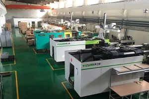
In our Shanghai factory, we run 47 injection molding machines from 90T to 1850T, producing parts with tight geometric controls for clients worldwide. Over 20+ years of experience with 400+ plastic materials, we have seen firsthand how proper GD&T specification prevents costly disputes between designers, toolmakers, and quality teams. This guide breaks down the key geometric tolerance types you need to know for injection molding, explains which ones matter most for plastic parts, and shares practical tips from the production floor.
- GD&T uses standardized symbols (ASME Y14.5 / ISO 1101) to define form, orientation, location, and runout.
- Плоскостность и прямолинейность являются наиболее критичными геометрическими допусками для литьевых деталей.
- Усадка материала и коробление делают геометрические допуски сложнее для соблюдения, чем при механической обработке металла.
- Выбор баз должен отражать функциональность сборки, а не только удобство обработки.
- Избыточное ужесточение геометрических допусков увеличивает стоимость оснастки и контроля, не добавляя ценности.
Что такое геометрические допуски и почему они важны при литье под давлением?
Geometric tolerances and why do they matter in injection molding are the main categories or options explained in this section. Geometric tolerances are the limits on allowable variation in a part’s form, orientation, and position beyond what linear dimensions alone can capture. A hole can be the correct diameter yet still be out of position; a surface can measure the right thickness yet be too warped to seal. GD&T addresses these realities with 14 tolerance types organized into five categories: form, orientation, location, runout, and profile.
На сайте литьё под давлениемгеометрические допуски особенно важны, потому что пластиковые детали подвергаются усадке, короблению и внутренним напряжениям во время охлаждения. Деталь, которая выглядит идеальной в момент извлечения, может деформироваться в течение следующих 24–48 часов по мере снятия остаточных напряжений. Это означает, что указанный вами геометрический допуск должен учитывать не только сам процесс литья, но и изменение размеров после литья. Например, требование плоскостности 0,1 мм на корпусе из поликарбоната длиной 150 мм может потребовать специальной конструкции литника, оптимизированного давления подпитки и, возможно, оснастки для фиксации детали во время охлаждения.
The ASME Y14.5 standard defines the complete symbolic language for GD&T in the United States, while ISO 1101 serves the same role internationally. Both standards use a feature control frame — a rectangular box containing the geometric characteristic symbol, the tolerance value, and any datum references. Understanding how to read and apply these frames is the foundation of communicating tolerance requirements to your injection mold supplier.
Which GD&T Symbols Are Most Relevant to Plastic Injection Molded Parts?
Not all 14 GD&T symbols are equally relevant to injection molding. In practice, a handful of geometric tolerances account for the vast majority of callouts on plastic part drawings. Here is a ranked breakdown of the most frequently used symbols and why they matter for molded components.
| GD&T Symbol | Category | Типовое применение | Сложность соблюдения |
|---|---|---|---|
| Плоскостность | Форма | Уплотнительные поверхности, монтажные плоскости | Высокий (коробление) |
| Прямолинейность | Форма | Ребра, кромки, цилиндрические элементы | Средний |
| Круглость | Форма | Цилиндрические бобышки, отверстия | Средний |
| Перпендикулярность | Ориентация | Бобышка к поверхности, стенка к фланцу | Средний и высокий |
| Параллельность | Ориентация | Противоположные стенки, защелкивающиеся элементы | Высокий |
| Позиция | Расположение | Массивы отверстий, точки крепления | Средний |
| Соосность | Расположение | Вращающиеся элементы, посадочные места подшипников | Очень высокий |
| Профиль поверхности | Профиль | Сложные криволинейные поверхности | Высокий |
Плоскостность, пожалуй, является самым важным геометрическим допуском для литьевых деталей. Уплотнительная поверхность, прогнувшаяся даже на 0,15 мм, может дать течь. Монтажная плоскость, покоробившаяся на 0,2 мм, может вызвать перекос при сборке. По нашему опыту, проблемы с плоскостностью составляют примерно 30-40% всех геометрических несоответствий на литьевых деталях. Основными причинами обычно являются неравномерное охлаждение, неудачное расположение литника или усадка материала, которая не была должным образом смоделирована при проектировании оснастки.
Position tolerance is the next most critical. When you have an array of mounting holes or snap-fit clips, their relative location determines whether the assembly goes together. Position tolerance is often more useful than individual coordinate tolerances because it allows bonus tolerance from the feature’s actual size — something particularly valuable with plastic parts where hole diameters can vary due to shrinkage.
Как выбор материала влияет на геометрический допуск при литье под давлением?
Выбранный вами материал оказывает прямое и часто значительное влияние на геометрические допуски, которых можно реально достичь. Аморфные материалы, такие как поликарбонат (ПК) и АБС, как правило, дают более равномерную усадку и сохраняют лучшую плоскостность по сравнению с полукристаллическими материалами, такими как нейлон (ПА6, ПА66) или ПОМ, которые подвержены значительной усадке из-за кристаллизации. Стеклонаполненные составы еще больше усложняют ситуацию, поскольку ориентация волокон создает анизотропную усадку — деталь усаживается по-разному вдоль направления потока и перпендикулярно ему.
Рассмотрим практический пример: плоская крышка размером 200 мм x 150 мм из PA66-GF30 (нейлон 66, наполненный 30% стекловолокна). mold flow simulation3 Может предсказать усадку 0,6% в направлении потока и 0,3% в поперечном направлении — соотношение 2:1. Если вы указываете плоскостность 0,1 мм, вы, вероятно, требуете того, что материал просто не может обеспечить без чрезвычайных мер, таких как приспособления в форме или отжиг после формования. Более реалистичное указание плоскостности для этого сценария составит 0,3–0,5 мм.
Здесь опытный поставщик литьевых форм добавляет реальную ценность. Имея 8 старших инженеров и опыт работы с более чем 400 материалами, мы помогаем клиентам понять, какие геометрические допуски достижимы для их конкретного материала, геометрии детали и объёма производства. Указание допусков, которые физически невозможно выдержать, не улучшает качество — это только увеличивает процент брака и стоимость.
“GD&T can specify tolerances that account for material shrinkage after molding.”Правда
By combining GD&T with mold flow simulation data, designers can predict post-shrinkage geometry and specify tolerances that reflect the part’s final equilibrium state, not just its as-molded condition.
“Tighter geometric tolerances always produce better parts.”Ложь
Завышение допусков увеличивает стоимость оснастки, время контроля и процент брака без улучшения функциональных характеристик. Правильный допуск — это самый широкий допуск, который всё ещё удовлетворяет требованиям сборки и функционирования.
Какие стандарты регулируют геометрические допуски для литьевых пластиковых деталей?
Стандарты геометрических допусков в основном регулируются двумя системами во всём мире: ASME Y14.5 и ISO 1101. ASME Y14.5 доминирует в Северной Америке, в то время как ISO 1101 (с сопутствующими стандартами ISO 5458 и ISO 5459) используется в Европе и Азии. Оба стандарта определяют одни и те же фундаментальные концепции, но различаются в некоторых деталях обозначений и правилах по умолчанию.
For injection molded parts specifically, ISO 20457:2018 provides additional guidance on dimensional tolerances for molded parts, including a classification system that accounts for mold-related factors like part geometry, gate location, and material behavior. This standard recognizes that plastic parts have fundamentally different tolerance capability than machined metal parts, and that applying machining-grade GD&T to molded plastics is economically unrealistic.
When preparing drawings for injection molding quotes, always specify which standard you are using. A tolerance frame interpreted under ASME Y14.5 may yield different results than the same frame under ISO 1101, particularly for position tolerances and datum usage. Misalignment on standards interpretation is one of the most common sources of quality disputes between buyers and molders.
How Do You Specify Geometric Tolerances on Injection Molded Part Drawings?
Three elements are needed to specify geometric tolerances: the tolerance type, the tolerance value, and the datum reference frame. The datum reference frame is arguably the most important — and most frequently misapplied — element. Datums define the reference surfaces from which all other measurements are taken. For injection molded parts, datum selection must consider how the part will be inspected, not just how it functions.
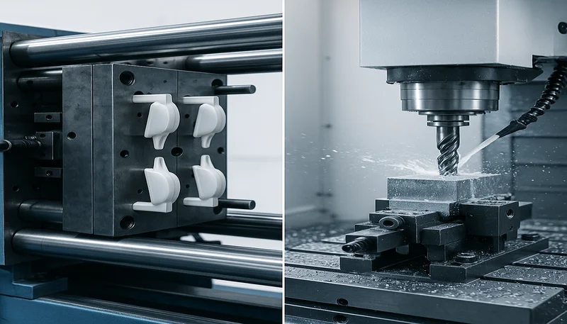
A common mistake is using the parting line as a datum. The parting line is the interface between the mold halves, and while it seems like a stable reference, it can flash, shift, or wear over the life of the mold. A better approach is to designate functional features — such as a flat mounting boss or a precision-bored hole — as datums. These features are directly machined into the mold steel and maintain their geometric integrity over hundreds of thousands of cycles.
Here is a practical specification workflow: First, identify the features that must mate with other components. Second, assign datums to the most stable and accessible of these features. Third, apply the loosest geometric tolerance that still guarantees function. Fourth, validate your callouts with your поставщик литья под давлением before finalizing the drawing — they can tell you what is realistically achievable given the part geometry, material, and production constraints.
What Causes Geometric Tolerance Deviations During Injection Molding?
Warpage, uneven cooling, ejection forces, and mold wear are the primary causes of geometric tolerance deviations during injection molding. Understanding these causes helps you set realistic tolerances and design more dimensionally stable parts.
Warpage is the number-one enemy of geometric tolerance in injection molding. It occurs when different regions of the part cool and shrink at different rates. Thin sections cool faster than thick sections. Areas near the gate receive more packing pressure than areas far from the gate. Fiber-filled materials develop internal stresses from oriented fibers that release as the part equilibrates. The result is a part that was geometrically correct in the mold but distorted when measured 24 hours later.

Ejection forces are another significant factor. As the part cools, it shrinks onto the mold core. The ejector pins must push the part off, and this force can temporarily distort thin walls or delicate features. Well-designed ejector systems distribute force evenly, but even optimal ejection can introduce sub-tenth-millimeter geometric deviations on critical surfaces.
Mold wear and maintenance also play a role. After 100,000+ cycles, mold surfaces can erode, especially around gate areas and sliding cores. This gradual wear shifts dimensions and can cause geometric features to drift out of tolerance. Regular mold maintenance and periodic first-article inspections are essential to catch this drift before it affects production quality.
“Mold flow simulation can predict geometric tolerance outcomes before steel is cut.”Правда
Modern mold flow simulation tools like Moldflow and Moldex3D can predict warpage, shrinkage, and fiber orientation with sufficient accuracy to validate geometric tolerance feasibility during the design phase.
“Post-mold annealing always improves geometric tolerance compliance.”Ложь
Annealing relieves internal stresses but can also cause additional distortion if not carefully controlled. For some materials and geometries, annealing actually worsens flatness or position accuracy. It must be evaluated case by case.
How Can You Optimize Part Design for Better Geometric Tolerance Compliance?
Uniform wall thickness, proper rib proportions, and strategic gate placement are the key design strategies for geometric tolerance compliance. These strategies improve dimensional stability without increasing cost.
Uniform wall thickness is the single most impactful design decision for geometric control. When wall thickness varies significantly across a part, thick sections shrink more than thin sections, creating internal stresses that cause warpage. A wall thickness variation greater than 15-20% in a crystalline material is almost guaranteed to produce geometric non-conformance on flat surfaces. Where thickness transitions are unavoidable, use gradual ramps instead of sharp steps to distribute stress more evenly.
Rib design also affects geometric outcomes. Ribs add stiffness, which helps maintain flatness — but they also create localized thick sections that shrink more than the surrounding wall. Keep rib thickness at 50-60% of the nominal wall thickness for most materials, and avoid intersecting ribs that create thick nodes. Corrugated wall sections can provide equivalent stiffness with better geometric stability than traditional ribs.
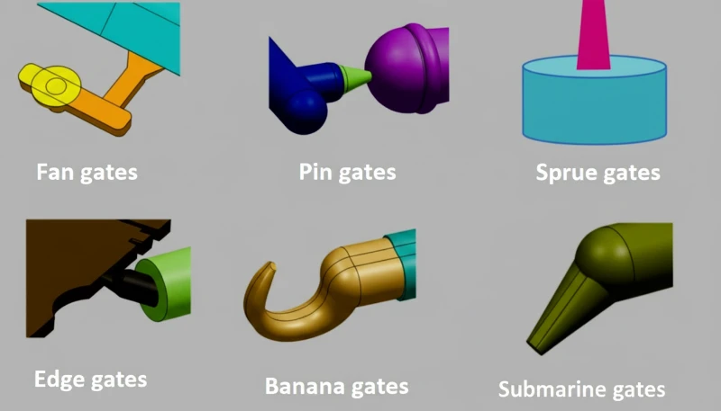
Gate location and type deserve careful consideration. The gate is where molten plastic enters the cavity, and its location determines the flow pattern, weld-line placement, and packing pressure distribution — all of which affect the final geometry. A single edge gate creates a unidirectional flow that favors parallelism along the flow direction. Multiple gates can balance filling but introduce weld lines that create weak points and geometric discontinuities.
ZetarMold’s quality team includes 10+ QC specialists who follow a 6-step inspection workflow covering IQC, in-process checks, and final OQC to verify geometric tolerance compliance on every production run.
How Do You Measure and Inspect Geometric Tolerances on Molded Parts?
CMMs, optical scanners, and functional gauges are the three primary methods for measuring geometric tolerances on injection molded plastic parts. Each method has specific advantages depending on the tolerance type and production volume.
CMM measurement with touch probes is the standard for position, perpendicularity, and parallelism checks. However, plastic parts are compliant — probe contact force can deflect the surface, introducing measurement error. Using low-probe-force CMMs (typically under 50 mN) or non-contact laser probes minimizes this issue. For flatness measurement, optical scanning with structured light provides full-surface data rather than the sparse point sets from touch probes, giving a more accurate picture of the actual surface condition.
Functional gauging remains the most practical method for high-volume production. A go/no-go gauge that simulates the mating component provides a pass/fail result that directly correlates with assembly function. While gauges cannot tell you exactly how much geometric deviation exists, they are fast, repeatable, and require minimal operator skill — making them ideal for in-process inspection on the production floor.
What Are Realistic Geometric Tolerance Ranges for Injection Molded Parts?
Geometric tolerance ranges for injection molded parts are typically between 0 and 1 mm, depending on tolerance type, material, and part geometry. The following table provides practical ranges based on industry experience and standard tolerance references for injection molding.
| Tolerance Type | Precision (Tight) | Standard (Normal) | Coarse (Loose) |
|---|---|---|---|
| Flatness (per 100 mm) | 0.05–0.10 mm | 0.10–0.30 mm | 0.30–0.60 mm |
| Straightness (per 100 mm) | 0.05–0.10 mm | 0.10–0.25 mm | 0.25–0.50 mm |
| Circularity (diameter) | 0.03–0.08 mm | 0.08–0.15 mm | 0.15–0.30 mm |
| Perpendicularity (per 100 mm) | 0.05–0.10 mm | 0.10–0.25 mm | 0.25–0.50 mm |
| Parallelism (per 100 mm) | 0.08–0.15 mm | 0.15–0.35 mm | 0.35–0.70 mm |
| Position (RFS) | Ø0.10–0.20 mm | Ø0.20–0.50 mm | Ø0.50–1.00 mm |
| Профиль поверхности | 0.10–0.20 mm | 0.20–0.50 mm | 0.50–1.00 mm |
These ranges assume standard processing conditions with optimized проектирование пресс-форм. Achieving the ‘Precision’ column typically requires specialized tooling features like conformal cooling, in-mold pressure sensors, and possibly post-mold fixturing. The ‘Standard’ column represents what a well-designed mold running on a modern injection molding machine can consistently produce. The ‘Coarse’ column is appropriate for non-critical aesthetic or structural features.
“Conformal cooling channels in the mold can improve flatness by up to 40%.”Правда
Conformal cooling channels follow the part contour, providing more uniform cooling that reduces thermal gradients and the resulting warpage. Studies show flatness improvements of 30-50% compared to conventional drilled channels.
“Glass-filled materials always improve dimensional stability and geometric tolerance.”Ложь
Glass fibers improve stiffness and reduce overall shrinkage, but they introduce anisotropic shrinkage that can worsen warpage and flatness. The fiber orientation depends on flow direction, so parallelism and flatness may actually degrade in certain orientations.
Why Should You Discuss Geometric Tolerance Requirements With Your Molding Supplier Early?
The biggest geometric tolerance problems we see in our factory are not caused by bad molding — they are caused by bad specification. Designers who finalize tolerances without consulting their injection mold supplier often specify tolerances that are either unrealistically tight or poorly targeted at non-critical features. Both mistakes waste money.
Early collaboration between the design team and the molding supplier enables several critical optimizations. First, the supplier can run mold flow simulations to validate whether the specified tolerances are achievable for the given geometry and material. Second, the tooling team can optimize gate location, cooling layout, and ejection strategy to target the most critical geometric features. Third, the quality team can design inspection protocols and fixtures that focus measurement effort on the features that matter most for function.
With our in-house mold manufacturing facility supporting 100+ mold sets per month, we can iterate on tool design quickly to achieve the best possible geometric tolerance outcomes. Our ISO 9001, ISO 13485, ISO 14001, and ISO 45001 certified quality systems ensure that geometric tolerance requirements are maintained throughout production, from first article to millionth part.
Need Precision Injection Molded Parts With Tight Geometric Tolerances?
ZetarMold is a Shanghai-based manufacturer delivering precision injection molded parts with tight geometric tolerances and 20+ years of experience. Our 8 senior engineers work with you from the design stage to optimize part geometry, material selection, and tool design for the best dimensional outcomes. Whether you need flat sealing surfaces within 0.1 mm or position tolerances for precision mounting holes, our team has the expertise and equipment to deliver. Get a free quote today and let us help you specify and achieve the right geometric tolerances for your project.
Frequently Asked Questions About Geometric Tolerances in Injection Molding
Часто задаваемые вопросы
What is the difference between dimensional tolerances and geometric tolerances?
Dimensional tolerances control the allowable variation in a single linear measurement such as a length, width, or diameter expressed as a plus or minus range. Geometric tolerances by contrast control the shape orientation or spatial relationship of a feature: how flat a surface is how perpendicular two faces are or how accurately a hole is positioned relative to a datum. For injection molded parts geometric tolerances are often more critical than dimensional ones because they directly determine whether components fit together and function properly in assembly. In practice most part drawings need both types to fully communicate design intent.
Can injection molding achieve the same geometric tolerances as CNC machining?
Generally no. CNC machining can routinely hold geometric tolerances of 0.01-0.05 mm because the cutting tool directly creates the geometry with minimal material behavior variability. Injection molding involves material shrinkage warpage and process variability that make tolerances below 0.05 mm impractical for most part geometries and materials. However injection molding is far more economical for high-volume production even with slightly looser tolerances. The key is to design parts that function reliably with the geometric tolerance range that molding can consistently deliver rather than forcing molding to match machining capabilities.
How does part size affect achievable geometric tolerance?
Larger parts are harder to hold to tight geometric tolerances because shrinkage accumulates over greater distances and uneven cooling becomes more pronounced. A flatness of 0.1 mm over 50 mm is achievable for most engineering plastics but the same 0.1 mm over 300 mm is extremely difficult in semi-crystalline materials. Tolerance specifications should scale with feature size often expressed as a percentage or per-unit-length value. A practical guideline is to expect flatness capability of approximately 0.1 to 0.2 percent of the feature length for amorphous materials and 0.2 to 0.4 percent for semi-crystalline materials.
What is the most common geometric tolerance mistake on plastic part drawings?
The most common mistake is over-tolerancing: specifying geometric tolerances that are tighter than functional requirements demand. This drives up tooling cost increases scrap rate and slows inspection throughput without any benefit to the end product. The second most common mistake is incorrect datum selection where the chosen datum features are not stable accessible or functionally relevant for measurement. Both mistakes often stem from applying metal-machining tolerance practices to plastic parts without accounting for the fundamental differences in how molded parts behave dimensionally during and after production.
Does using a higher-pressure injection molding machine improve geometric tolerances?
Higher injection pressure alone does not improve geometric accuracy. Packing pressure must be carefully optimized for each part and material combination. Too little pressure causes short shots and sink marks while too much pressure causes flash over-packing and internal stresses that lead to warpage and dimensional instability. Process optimization through scientific molding principles including decoupled filling and packing stages with pressure and temperature sensors is far more effective than simply increasing machine tonnage or injection pressure without a systematic approach.
How soon after molding should you measure geometric tolerances?
For most engineering plastics you should wait at least 24 hours after molding before taking critical geometric measurements. Some semi-crystalline materials like nylon and PEEK continue to dimensionally stabilize for up to 48-72 hours due to ongoing post-crystallization and stress relaxation. Amorphous materials like polycarbonate and ABS stabilize faster but still benefit from a minimum 12 to 24 hour equilibration period. Measuring too early gives misleading results that do not reflect the part final geometry and can lead to incorrect process adjustments that actually worsen quality outcomes.
Can you use GD&T on 3D-printed injection molds for prototyping?
3D-printed molds such as those made with SLA resin or metal powder bed fusion can produce prototype parts for form and fit testing. However the geometric tolerance capability is significantly looser than production steel molds because printed molds have lower thermal conductivity less precise cavity surfaces and limited pressure resistance. Expect tolerances 3 to 5 times wider than what a hardened tool steel mold can achieve. GD&T callouts on prototype parts should be clearly marked as preliminary and re-evaluated when transitioning to production tooling made from hardened steel.
What role does mold temperature play in geometric tolerance control?
Mold temperature directly affects cooling rate crystallization behavior and residual stress formation all of which influence the final geometric accuracy of the molded part. Higher mold temperatures produce more uniform cooling and lower internal stresses which typically improves flatness and warpage control. However higher mold temperature also increases cycle time and production cost. For semi-crystalline materials mold temperature also affects the degree of crystallization which in turn affects shrinkage magnitude. Finding the optimal mold temperature is a balance between geometric quality production efficiency and cost considerations.
-
ASME Y14.5: ASME Y14.5 refers to the American national standard for geometric dimensioning and tolerancing, published by the American Society of Mechanical Engineers. ↩
-
ISO 1101: ISO 1101 refers to the international standard for geometrical product specifications (GPS) — geometrical tolerancing — tolerances of form, orientation, location and run-out. ↩
-
mold flow simulation: моделирование потока расплава относится к вычислительному анализу процесса литья под давлением, который предсказывает картину заполнения, распределение давления и коробление до изготовления пресс-формы. ↩




 EN
EN  ES
ES  FR
FR  DE
DE  PT
PT  AR
AR  RU
RU  JA
JA  KO
KO  IT
IT  NL
NL  TR
TR  PL
PL 