Czym jest chłodzenie formy wtryskowej i dlaczego ma znaczenie?
Po pracy z układami chłodzenia w ponad 47 wtryskarkach w naszym zakładzie w Szanghaju mogę stwierdzić, że projekt chłodzenia decyduje o powodzeniu lub niepowodzeniu większości projektów form. Zadanie układu chłodzenia jest proste: jak najszybciej i równomiernie odprowadzić ciepło ze stopionego tworzywa, aby detal prawidłowo się zestalił i można go było wyjąć z formy bez wad.
Oto fakt, który wiele osób pomija — chłodzenie zajmuje 60–70% całkowitego czasu cyklu formowania wtryskowego1. Jeśli część chłodzi się 20 sekund, a wtrysk i wyrzut trwają łącznie tylko 8 sekund, cały cykl wynosi 28 sekund. Skrócenie chłodzenia do 15 sekund zwiększa wydajność produkcji o niemal 20%.
Układ chłodzenia składa się z kanałów wykonanych w formie, którymi przepływa czynnik chłodzący (zwykle woda), odprowadzając ciepło. Kanały te muszą być rozmieszczone tak, aby zapewnić równomierne chłodzenie całej geometrii części. Nierównomierne chłodzenie powoduje naprężenia wewnętrzne objawiające się wypaczeniem, niestabilnością wymiarową i słabym wykończeniem powierzchni.
Widziałem formy ze źle zaprojektowanymi układami chłodzenia, które wytwarzały detale z odkształceniem 0.5mm na powierzchniach, które powinny być płaskie. Po przeprojektowaniu chłodzenia te same detale utrzymywały tolerancję w granicach 0.05mm. To różnica między brakami a rentowną produkcją.
Jakie są kluczowe parametry projektowania kanałów chłodzących?
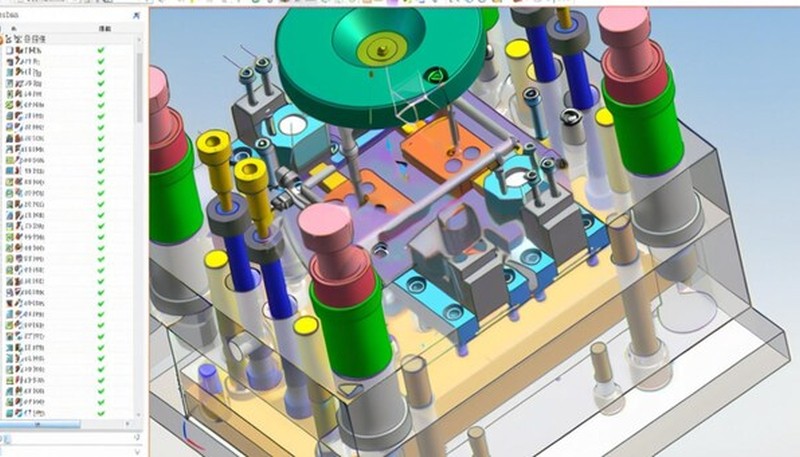
Punktem wyjścia jest średnica kanału. Większość kanałów chłodzących ma średnicę od 8mm do 16mm, przy czym 10-12mm to optymalny zakres dla większości zastosowań. Większe kanały nie zawsze oznaczają lepsze chłodzenie – potrzebna jest odpowiednia prędkość wody, aby utrzymać przepływ turbulentny zapewniający skuteczną wymianę ciepła. Zazwyczaj dążę do wartości liczby Reynoldsa powyżej 5000, aby uzyskać optymalny współczynnik wymiany ciepła.
Rozstaw kanałów określa zasada 2-3 średnic. Kanały o średnicy 10mm należy rozmieścić w odstępach 20-30mm, licząc od osi do osi. Mniejszy rozstaw poprawia równomierność chłodzenia, ale zwiększa koszty obróbki. Większy rozstaw powoduje powstawanie gorących punktów między kanałami, w których chłodzenie jest mniej skuteczne.
Odległość od powierzchni gniazda ma ogromne znaczenie. Kanały należy prowadzić w odległości równej 1.5-2.5-krotności ich średnicy od powierzchni gniazda. Zbyt mała odległość grozi przebiciem podczas obróbki lub powstaniem osłabionych miejsc w stali formy. Zbyt duża znacząco obniża wydajność chłodzenia.
Regulacja temperatury wody wymaga większej uwagi, niż zwykle się zakłada. Temperatura na wlocie wynosi zazwyczaj 10°C–40°C zależnie od materiału. Różnica między wlotem a wylotem powinna pozostać poniżej 5°C; większa wskazuje niedostateczny przepływ lub złą konstrukcję kanałów.
Obliczenie natężenia przepływu wymaga zrównoważenia spadku ciśnienia z wymaganiami dotyczącymi odprowadzania ciepła. Jako wartość początkową przyjmuję 2–4 litry na minutę na kanał, a następnie koryguję ją na podstawie obliczonego obciążenia cieplnego. Wyższe natężenie przepływu poprawia wymianę ciepła, lecz zwiększa koszty pompowania i wymagane ciśnienie.
Jakie są rodzaje układów kanałów chłodzących?
Proste kanały chłodzące są najpowszechniejszym i najbardziej ekonomicznym rozwiązaniem. Woda wpływa z jednej strony formy i wypływa z drugiej, przemieszczając się po prostej. Takie kanały dobrze sprawdzają się przy prostych geometriach, lecz są mniej skuteczne w przypadku złożonych kształtów lub obszarów oddalonych od krawędzi formy.
Chłodzenie szeregowe łączy wiele kanałów kolejno, tworząc w formie układ serpentynowy. Rozwiązanie to sprawdza się, gdy określone obszary wymagają chłodzenia w kontrolowanej sekwencji. Wadą jest wzrost temperatury wody podczas przepływu przez obieg, co powoduje powstawanie gradientów temperatury.
Chłodzenie równoległe zasila wiele kanałów jednocześnie ze wspólnego kolektora. Do każdego kanału dopływa woda o tej samej temperaturze początkowej, co zapewnia bardziej równomierne chłodzenie niż w obiegach szeregowych. To moje preferowane rozwiązanie dla większości form wtryskowych2, gdy pozwala na nie miejsce na kolektor.
Chłodzenie spiralne tworzy śrubową ścieżkę wokół cylindrycznych rdzeni lub trzpieni. Konstrukcja ta zapewnia doskonałą równomierność temperatury elementów okrągłych, lecz wymaga precyzyjnej obróbki, aby utrzymać stałą średnicę kanału na całej długości spirali.
Chłodzenie z przegrodą wykorzystuje wewnętrzne przegrody do kierowania przepływem chłodziwa w ciasnych przestrzeniach, takich jak wąskie rdzenie. Chłodziwo wpływa przez rurkę, uderza w płytę przegrody i wraca po zewnętrznej stronie rurki. Zapewnia to maksymalną intensywność chłodzenia w miejscach, w których nie mieszczą się konwencjonalne kanały.
Chłodzenie fontannowe wykorzystuje rurkę wprowadzoną do wierconego otworu; chłodziwo płynie środkiem i wraca przestrzenią zewnętrzną. Rozwiązanie skutecznie chłodzi głębokie rdzenie, lecz wymaga starannego uszczelnienia. Stosuję je, gdy średnice rdzeni są zbyt małe dla zwykłych kanałów.
Jak chłodzenie konformalne poprawia działanie formy?
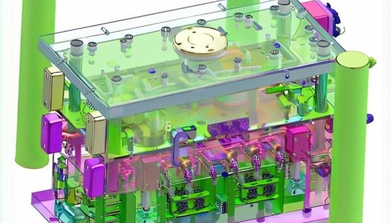
Konformalne kanały chłodzące odwzorowują kontur geometrii detalu, zachowując stałą odległość od powierzchni gniazda niezależnie od jego złożoności. Tradycyjne kanały proste nie zapewniają takiej równomierności w przypadku geometrii zakrzywionych lub złożonych, co prowadzi do powstawania gorących punktów i nierównomiernego chłodzenia.
Proces wytwarzania wykorzystuje technologię addytywną (druk 3D) do wykonywania wkładek formujących z wewnętrznymi kanałami konformalnymi. Wkładki drukujemy z proszków stali narzędziowej, a następnie obrabiamy wykańczająco powierzchnie gniazd do wymiarów końcowych. Pozwala to uzyskać geometrię kanałów niemożliwą do wykonania metodami konwencjonalnej obróbki.
Dobrze zaprojektowane chłodzenie konformalne zwykle skraca cykl o 15-30%, a przy grubych ściankach lub złożonej geometrii nawet bardziej. Kluczowa jest stała odległość kanału od powierzchni, nieosiągalna dla kanałów prostych.
Chłodzenie konformalne znacząco poprawia równomierność temperatury. W przypadku tradycyjnych kanałów różnice temperatury na powierzchni części mogą wynosić 10-15°C, natomiast układy konformalne często zapewniają równomierność w zakresie 3-5°C. Przekłada się to bezpośrednio na mniejsze wypaczenie i lepszą stabilność wymiarową.
Korzyści jakościowe nie ograniczają się do dokładności wymiarowej. Bardziej równomierne chłodzenie zmniejsza naprężenia wewnętrzne, poprawiając udarność i trwałość zmęczeniową. Poprawia się również jakość powierzchni, ponieważ ograniczone zostają gradienty temperatury powodujące smugi płynięcia i inne wady.
Koszty obejmują wyższy początkowy koszt oprzyrządowania, lecz szybszy zwrot dzięki krótszym cyklom. W produkcji wielkoseryjnej oszczędność czasu cyklu zwykle uzasadnia dodatkową inwestycję w ciągu 6-12 miesięcy.
Jakie typowe problemy z chłodzeniem powodują wady detali?
W naszym zakładzie w Szanghaju, wyposażonym w 47 wtryskarek, monitorowaliśmy wady związane z chłodzeniem w 400+ różnych formulacjach tworzyw. Z naszego doświadczenia wynika, że niewłaściwie zaprojektowane chłodzenie odpowiada za niemal 40% wszystkich problemów z jakością części. Naszych 8 inżynierów opracowało standardowe obliczenia układu chłodzenia, które zmniejszyły liczbę wad paczenia o 65% w porównaniu z tradycyjnymi metodami opartymi na regułach praktycznych.
Odkształcenia są najczęstszymi wadami związanymi z chłodzeniem. Nierównomierne chłodzenie powoduje zróżnicowany skurcz w obrębie części, prowadząc do jej wygięcia, skręcenia lub deformacji. Grube przekroje chłodzą się wolniej niż cienkie, co powoduje naprężenia wewnętrzne odkształcające część. Widziałem przypadki, w których obszary o grubości 2mm nadal się chłodziły, podczas gdy przekroje 0.5mm były już zestalone, co prowadziło do trwałego odkształcenia.
Zapadnięcia powstają, gdy grube przekroje kurczą się podczas chłodzenia bardziej niż otaczający je materiał. Powierzchnia zostaje wciągnięta do środka, tworząc widoczne wgłębienia. Dzieje się tak, gdy kanały chłodzące znajdują się zbyt daleko od grubych obszarów lub czas chłodzenia jest niewystarczający do pełnego zestalenia.
Niestabilność wymiarowa objawia się tym, że części mają prawidłowe wymiary na gorąco, lecz po osiągnięciu temperatury pokojowej kurczą się poza tolerancję. Oznacza to niepełne schłodzenie w formie — części wypchnięto przed osiągnięciem równowagi cieplnej. Wydłużenie chłodzenia zwykle rozwiązuje problem, ale zapobiega mu prawidłowa konstrukcja kanałów.
Osłabienie linii łączenia występuje, gdy kanały chłodzące powodują nierównowagę temperatury w obszarze styku frontów płynięcia. Jeżeli jedna strona chłodzi się szybciej od drugiej, linia łączenia powstaje przy różnych temperaturach, co obniża wytrzymałość połączenia. Zrównoważone chłodzenie wokół linii łączenia ma kluczowe znaczenie dla integralności konstrukcyjnej.
Wady powierzchni, takie jak ślady płynięcia i przebarwienia przy przewężce, często wynikają z nierównomiernej temperatury formy. Miejscowe przegrzania powodują różnice w przepływie tworzywa, pozostawiając widoczne ślady na powierzchni. Utrzymanie równomiernej temperatury formy dzięki prawidłowo zaprojektowanemu układowi chłodzenia eliminuje większość wad powierzchniowych.
Problemy z wypychaniem powstają, gdy detale nie są chłodzone równomiernie. Niedostatecznie schłodzone obszary odkształcają się podczas wypychania, natomiast miejsca przechłodzone stają się zbyt sztywne i pękają. Równomierne chłodzenie zapewnia jednakową sztywność detalu i niezawodne wypychanie.
Jak obliczyć czas chłodzenia w formowaniu wtryskowym?
Podstawowy wzór na czas chłodzenia ma postać: t = h²/(π² × α), gdzie t oznacza czas chłodzenia, h — grubość ścianki, a α — dyfuzyjność cieplną tworzywa. Równanie zakłada, że środek części osiąga temperaturę wypychania po zakończeniu chłodzenia powierzchni.
Dyfuzyjność cieplna (α) uwzględnia gęstość materiału, ciepło właściwe i przewodność cieplną. Dla popularnych tworzyw sztucznych: ABS ≈ 1.1 × 10⁻⁷ m²/s, PP ≈ 1.0 × 10⁻⁷ m²/s, PC ≈ 1.4 × 10⁻⁷ m²/s. Wartości te zmieniają się zależnie od temperatury i zawartości wypełniacza, dlatego należy korzystać z danych dostawcy materiału, jeżeli są dostępne.
Dla bezpieczeństwa jako grubość ścianki (h) przyjmuje się grubość maksymalną, chociaż grubość średnia daje bardziej realistyczne czasy. W przypadku części o zmiennej grubości czas chłodzenia należy obliczyć dla najgrubszego przekroju — cieńsze obszary ostygną szybciej i nie będą ograniczać czasu cyklu.
Przykład praktyczny: detal z ABS o grubości 3mm. Przyjmując α = 1.1 × 10⁻⁷ m²/s: t = (0.003)²/(π² × 1.1 × 10⁻⁷) = 9 × 10⁻⁶/(1.09 × 10⁻⁶) = 8.3 sekundy. Po dodaniu 20-30% marginesu bezpieczeństwa na warunki rzeczywiste otrzymujemy czas chłodzenia wynoszący około 10-11 sekund.
Warunki temperaturowe znacząco wpływają na obliczenia. Wzór zakłada chłodzenie od temperatury stopionego tworzywa do temperatury wypychania, zwykle 60-80°C dla większości tworzyw termoplastycznych. Niższa temperatura wypychania wymaga dłuższego czasu chłodzenia, lecz poprawia stabilność wymiarową.
Temperatura formy wpływa na chłodzenie przez gradient cieplny. Wyższa zmniejsza gradient i wydłuża chłodzenie, ale poprawia powierzchnię i ogranicza naprężenia. Czas cyklu należy zrównoważyć z wymaganiami jakości.
Walidacja wymaga pomiaru rzeczywistej temperatury wypraski w momencie wypychania za pomocą termometrii na podczerwień lub termopar. Jeśli temperatura rdzenia przekracza cele dla wypychania, zwiększ czas chłodzenia. Jeśli temperatura powierzchni jest zbyt niska, skróć czas chłodzenia lub zwiększ temperaturę formy, aby zapobiec przechłodzeniu.
Jakie są najczęściej zadawane pytania dotyczące projektowania chłodzenia form?
Jak blisko kanalów chłodzących można się umieścić względem powierzchni wnęki?
Minimalna odległość powinna wynosić 1,5-krotność średnicy kanału, ale 2-2,5-krotność średnicy jest bezpieczniejsza w większości zastosowań. Dla kanałów 10 mm zachowaj odległość co najmniej 15 mm od powierzchni gniazda, najlepiej 20-25 mm. Zbyt bliskie umieszczenie grozi przebiciem podczas obróbki, tworzy słabe punkty w stali i może powodować nierównomierne chłodzenie z powodu nadmiernego strumienia ciepła. Dokładna odległość zależy od twardości stali formy, dokładności obróbki i wymagań chłodzenia. Twardsze stale pozwalają na bliższe umieszczenie, podczas gdy miększe stale potrzebują więcej materiału dla integralności strukturalnej.
Jaka jest optymalna temperatura wody do chłodzenia form wtryskowych?
Temperatura wody zależy od materiału tworzywa i wymagań dotyczących wypraski. Większość termoplastów dobrze działa przy temperaturze wody na wlocie 10-40°C. Niższe temperatury (10-20°C) zapewniają szybsze chłodzenie, ale mogą powodować wady powierzchni, takie jak ślady przepływu lub słaby połysk. Wyższe temperatury (30-40°C) poprawiają wykończenie powierzchni, ale wydłużają czas cyklu. Materiały częściowo krystaliczne, takie jak PP i PE, korzystają z wyższych temperatur formy, aby promować krystalizację. Utrzymuj różnicę temperatur wlot-wylot poniżej 5°C dla jednolitego chłodzenia w obwodzie.
Jak zapobiegać przeciekom kanałów chłodzących w formach wtryskowych?
Prawidłowe uszczelnienie zaczyna się od precyzyjnej obróbki – kanały muszą być proste, okrągłe i mieć gładkie powierzchnie. Używaj odpowiednich rowków pod O-ringi dobranych do ciśnienia roboczego i temperatury. Standardowe O-ringi NBR sprawdzają się w większości zastosowań, ale do zastosowań wysokotemperaturowych lub chemoodpornych używaj FKM (Viton). Uszczelniacz gwintów na złączkach rurowych zapobiega przeciekom w połączeniach. Regularna konserwacja obejmuje wymianę O-ringów i sprawdzanie korozji lub erozji, które tworzą drogi przecieku. Przetestuj wszystkie obwody pod ciśnieniem 1,5-krotności ciśnienia roboczego przed produkcją.
Czy można zmodernizować istniejące formy za pomocą lepszych systemów chłodzenia?
Modernizacja jest często możliwa, lecz wymaga starannej oceny grubości i układu istniejących elementów stalowych. Dodanie kanałów może wymagać spawania i ponownej obróbki, co stwarza ryzyko odkształceń i wpływa na właściwości stali. Czasami bardziej opłacalna jest wymiana wkładek niż modyfikacja istniejącej stali. Modernizacja do chłodzenia konformalnego zwykle nie jest praktyczna ze względu na konieczność zastosowania wytwarzania przyrostowego. Należy skoncentrować się na optymalizacji połączeń istniejących kanałów, poprawie rozdziału przepływu za pomocą kolektorów albo dodaniu chłodzenia w obszarach dotychczas niechłodzonych. Każdy przypadek wymaga indywidualnej oceny kosztów i korzyści.
Jaki przepływ powinna mieć woda chłodząca w formach wtryskowych?
Celuj w 2–4 litry na minutę na kanał dla większości zastosowań, z liczbą Reynoldsa powyżej 5000 dla przepływu turbulentnego. Wyższe przepływy poprawiają wymianę ciepła, ale zwiększają spadek ciśnienia i koszty pompowania. Oblicz przepływ na podstawie wymagań odprowadzania ciepła: Q = m × cp × ΔT, gdzie Q to obciążenie cieplne, m to masowy przepływ, cp to ciepło właściwe wody, a ΔT to przyrost temperatury. Typowy spadek ciśnienia powinien pozostać poniżej 2–3 bar na obwód. Używaj przepływomierzy i manometrów do monitorowania każdego obwodu podczas produkcji.
Jak geometria części wpływa na projekt kanałów chłodzących?
Złożone geometrie wymagają kreatywnych rozwiązań chłodzących, aby utrzymać jednolite temperatury. Głębokie żebra potrzebują dedykowanych linii chłodzących lub fontann (bubblers), aby zapobiec gorącym punktom. Grube przekroje korzystają z wielu obwodów chłodzących w różnych odległościach od powierzchni. Podcięcia i elementy boczne mogą wymagać chłodzenia w suwakach lub podnośnikach. Cienkie ścianki wymagają starannego rozstawu kanałów, aby uniknąć przechłodzenia powodującego kruchość. Duże płaskie powierzchnie korzystają z równoległych kanałów rozmieszczonych zgodnie z zasadą 2-3 średnic. Zawsze priorytetowo chłodź najgrubsze sekcje, ponieważ one kontrolują czas cyklu.
Jakiej konserwacji wymagają systemy chłodzenia form wtryskowych?
Regularne płukanie zapobiega osadzaniu się kamienia i korozji, co zmniejsza efektywność chłodzenia. Używaj filtrowanej wody i rozważ systemy uzdatniania wody w obszarach z twardą wodą. Miesięczne kontrole przepływu pozwalają wcześnie wykryć zatory lub wycieki. Coroczne czyszczenie obwodów odpowiednimi środkami odkamieniającymi usuwa osady mineralne. Wymieniaj uszczelki O-ring podczas planowanych przeglądów. Monitoruj wzrost temperatury wody w obwodach – rosnąca różnica temperatur wskazuje na zmniejszony przepływ lub spadek efektywności wymiany ciepła. Trzymaj zapasowe złącza szybkozłączne i uszczelki O-ring do szybkich napraw podczas produkcji.
Jak chłodzić złożone geometrie, takie jak gwinty lub podcięcia?
Obszary gwintowane często wymagają spiralnych kanałów chłodzących prowadzonych zgodnie ze skokiem gwintu albo gęsto rozmieszczonych kanałów prostych wokół rdzenia gwintowanego. Podcięcia wykonywane przez suwaki wymagają oddzielnych obiegów chłodzenia połączonych elastycznymi przewodami lub złączami obrotowymi. W głębokich kieszeniach, w których nie mieszczą się konwencjonalne kanały, sprawdza się chłodzenie fontannowe za pomocą rurek fontannowych. Niekiedy zaakceptowanie nieco dłuższego czasu cyklu jest bardziej opłacalne niż stosowanie złożonych układów chłodzenia. W pierwszej kolejności należy chłodzić obszary o największej masie cieplnej, a następnie — jeśli pozwala na to czas cyklu — mniejsze elementy. Doświadczenie ZetarMold w pracy ze złożonymi geometriami pomaga optymalizować chłodzenie w takich wymagających zastosowaniach.
Dlaczego warto wybrać ZetarMold do optymalizacji chłodzenia form?
Nasz zakład w Szanghaju doskonali projektowanie systemów chłodzenia od 2005 roku, posiadając certyfikaty ISO 9001, 13485, 14001 i 45001, które zapewniają spójne procesy jakościowe. Nasz zespół 8 inżynierów opracował własne obliczenia i wytyczne projektowe dotyczące chłodzenia, oparte na praktycznym doświadczeniu z ponad 400 różnymi formulacjami żywic w naszych 47 maszynach do wtrysku.
ZetarMold wyróżnia systematyczne podejście do optymalizacji chłodzenia. Nie opieramy się na przestarzałych regułach praktycznych — każdy układ chłodzenia projektujemy przy użyciu oprogramowania do analizy cieplnej i walidujemy rzeczywistymi pomiarami temperatury. Wśród ponad 120 pracowników mamy przeszło 30 inżynierów posługujących się językiem angielskim, którzy potrafią jasno omawiać złożone wymagania techniczne na każdym etapie rozwoju projektu.
Gotowy na optymalizację systemu chłodzenia formy?
Uzyskaj ekspercką analizę projektu chłodzenia dla swojego następnego projektu formowania wtryskowego3
- Zaawansowane techniki optymalizacji procesu wtrysku i strategie redukcji czasu cyklu
- Kompleksowe zasady projektowania form, w tym integracja systemu chłodzenia i zarządzanie termiczne
- Profesjonalne usługi wtrysku z zaawansowanym projektowaniem i optymalizacją systemu chłodzenia