 Przejdź do treści

- Polycarbonate delivers 250 times the impact resistance of glass at half the weight, with 92% light transmittance for optical-grade applications.
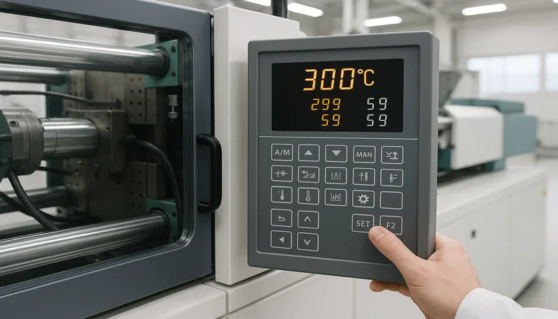
- Successful PC molding requires barrel temperatures of 280 to 320 degrees Celsius, mold temperatures of 80 to 120 degrees Celsius, and material drying at 120 degrees Celsius for 2 to 4 hours.
- Uniform wall thickness between 1.5 mm and 4.0 mm prevents warpage, sink marks, and internal stress that cause premature failure in polycarbonate parts.
- Post-mold annealing at 125 to 135 degrees Celsius for 1 to 4 hours relieves internal stress and prevents environmental stress cracking in high-performance applications.
- ZetarMold processes over 400 engineering plastics including multiple PC grades on 47 injection molding machines with tonnages from 30 to 1600 tons.
What Makes Polycarbonate the Preferred Material for Impact-Resistant Transparent Parts?
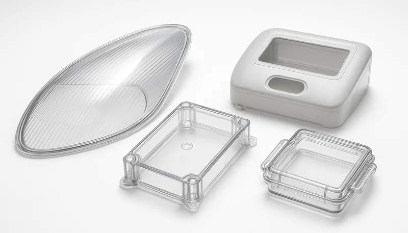
poliwęglan1 delivers 250 times the impact resistance of glass at roughly half the weight, making it the default choice for protective covers, optical lenses, and structural glazing in industries from automotive to consumer electronics. Its amorphous molecular structure produces 92% light transmittance—matching optical glass—while withstanding temperatures up to 135°C in continuous service. For a complete overview, see our injection molding complete guide oraz injection mold complete guide.
Why Polycarbonate Outperforms Competing Polymers
Unlike semicrystalline polymers such as nylon or POM, polycarbonate maintains dimensional stability across a wide temperature range because it does not undergo crystallization during cooling. This property simplifies the injection molding process for tight-tolerance parts where thermal expansion behavior must remain predictable.
The bisphenol-A backbone of polycarbonate provides a unique combination of toughness and transparency that no other commercial polymer replicates. Acrylic matches PC in clarity but shatters on impact. Nylon absorbs too much moisture for optical stability. Polyethylene terephthalate (PET) offers moderate impact resistance but requires crystallization control that complicates transparent molding.
| Własność | Poliwęglan (PC) | PMMA (Acrylic) | Glass |
|---|---|---|---|
| Impact Strength (Notched Izod) | 600–900 J/m | 15–25 J/m | ~2 J/m |
| Light Transmittance | 92% | 93% | 91% |
| Gęstość | 1.20 g/cm³ | 1.18 g/cm³ | 2.50 g/cm³ |
| Max Service Temperature | 135°C | 85°C | 500°C+ |
| UV Resistance | Fair (needs stabilizer) | Dobry | Doskonały |
| Relative Cost | Średni | Niski | Low–High |
In our factory, we frequently recommend PC over acrylic for any part that faces impact risk. A PMMA lens shatters at 20 J/m impact energy—a polycarbonate version absorbs 30 times that force without permanent deformation. The weight savings compared to glass (1.20 vs. 2.50 g/cm³) also reduce shipping costs significantly for high-volume consumer products shipped internationally.
PC grades with UV stabilizers extend outdoor service life beyond 10 years without significant yellowing. For indoor electronics housings and LED diffusers, standard optical-grade PC provides the clarity and toughness combination that no other single polymer can match. The self-extinguishing nature of polycarbonate (UL 94 V-2 rating at 1.5 mm) adds a natural fire safety benefit without requiring flame retardant additives for many applications.
Polycarbonate also excels in dimensional stability. With a linear coefficient of thermal expansion of 65–70 × 10⁻⁶ /°C—lower than most engineering plastics—PC parts maintain tight tolerances across a temperature range from −40°C to 130°C. This thermal stability makes it the material of choice for precision optical assemblies and aerospace window panels where dimensional accuracy cannot be compromised.
What Are the Critical Processing Parameters for Polycarbonate Injection Molding?
Successful polycarbonate injection molding requires barrel temperatures between 280°C and 320°C, mold temperatures of 80–120°C, and injection pressures of 80–150 MPa to fill complex geometries without introducing internal stress. These parameters are significantly higher than those for commodity plastics like ABS (220–260°C barrel), reflecting PC’s higher melt viscosity and sensitivity to thermal degradation.
Moisture is the single largest source of defects in PC molding. Polycarbonate absorbs up to 0.35% moisture from ambient air, and even 0.02% residual moisture at melt temperature causes hydrolytic chain scission—resulting in splay marks, reduced impact strength, and hazy surfaces. Drying at 120°C for 2–4 hours in a dehumidifying dryer with a dew point at or below −30°C is mandatory before every production run.
Injection Speed, Back Pressure, and Drying
Injection speed profile matters as much as temperature for PC part quality. A slower initial speed (20–30% capacity) through the gate prevents jetting and gate blush, followed by a faster speed (60–80% capacity) for cavity filling. This two-stage profile reduces shear stress at the gate area while maintaining sufficient pressure to fill thin-wall sections completely before the melt front freezes.
Back pressure during plasticization should remain between 0.5 and 1.5 MPa for standard PC grades. Insufficient back pressure allows air bubbles to become trapped in the melt, creating internal voids that reduce both mechanical strength and optical clarity. Excessive back pressure generates shear heat that raises melt temperature beyond the target range and accelerates degradation.
| Parametr | Zalecany zakres | Effect of Deviation |
|---|---|---|
| Temperatura beczki | 280–320°C | Bez wyżarzania, świeżo odlana część z PC przenosi 10–25 MPa naprężeń wewnętrznych wynikających z różnicowego chłodzenia. Lokalizacja wlewów, układ kanałów chłodzących oraz zmienność grubości ścianek przyczyniają się do tych naprężeń szczątkowych. Naprężenia są niewidoczne podczas wstępnej kontroli jakości, ale powodują opóźnione uszkodzenia – pęknięcia pojawiające się tygodnie lub miesiące po montażu, szczególnie w pobliżu kołnierzy, zaczepów i obszarów pozostałości po wlewach. |
| Temperatura formy | 80–120°C | Too low: surface stress; too high: long cycle |
| Prędkość wtrysku | Medium–High (staged) | Too slow: freeze-off; too fast: jetting |
| Ciśnienie wtrysku | 80–150 MPa | Too low: voids; too high: flash |
| Hold Pressure | 40–60% of injection | Too low: sink marks; too high: residual stress |
| Temperatura suszenia | 120°C for 2–4 h | Insufficient: splay, haze, chain degradation |
| Ciśnienie wsteczne | 0.5–1.5 MPa | Too low: air entrapment; too high: shear heat |
Screw speed should stay below 60 RPM for standard PC grades to minimize shear heating. Excessive screw speed raises localized melt temperature above 340°C, triggering thermal degradation that turns the polycarbonate yellow and drops its impact strength by up to 40%. We’ve found that a screw compression ratio of 2.0:1 to 2.5:1 provides the best balance between melt homogeneity and thermal safety.
Cushion size—the material remaining in the barrel after injection—should be maintained between 5 and 10 mm. A cushion that is too small prevents adequate packing pressure transmission. A cushion that is too large increases residence time, raising the risk of thermal degradation. For transparent PC parts, consistent cushion size from shot to shot also stabilizes part weight and dimensional accuracy.
Cooling time for polycarbonate typically runs 20–40% longer than for ABS parts of equivalent wall thickness because PC’s higher glass transition temperature (147°C vs. 105°C for ABS) requires the part to cool further before it is dimensionally stable enough for ejection. Premature ejection warps the part and creates ejector pin marks that are difficult to remove from PC’s glossy surface.
How Does Wall Thickness Affect Polycarbonate Part Quality and Moldability?
Uniform wall thickness between 1.5 mm and 4.0 mm is the single most critical design factor for polycarbonate injection molding quality. Thickness variations exceeding a 3:1 ratio within the same part create differential cooling rates that produce internal stress concentrations exceeding 15 MPa—enough to trigger environmental stress cracking when the part contacts solvents or UV radiation.
Thick and Thin Wall Challenges
Thin walls below 1.0 mm require injection pressures above 160 MPa and mold temperatures above 110°C to achieve complete fill. While PC can be molded as thin as 0.5 mm in small areas, the required processing window narrows dramatically, increasing reject rates from a typical 2–3% to over 15%. Analiza przepływu formy2 becomes essential for any part with sections thinner than 1.0 mm to verify fill patterns and pressure requirements before committing to tooling.
Thick-wall sections above 4.0 mm create their own challenges. Cooling time increases proportionally to the square of wall thickness, so doubling thickness from 2.0 mm to 4.0 mm quadruples cooling time and extends cycle time from roughly 25 seconds to over 60 seconds. Thick sections also trap residual heat that creates vacuum voids at the core—visible as internal bubbles in transparent PC parts.
Transition zones between thick and thin sections should use gradual tapers with a slope no steeper than 3:1 (3 mm horizontal for every 1 mm vertical change). Abrupt thickness changes create stress risers at the transition boundary and are the most common origin point for stress cracks in polycarbonate parts exposed to chemical environments.
“Polycarbonate requires uniform wall thickness within a 1.5:1 ratio to prevent warpage and internal stress cracking.”Prawda
Differential cooling across thick and thin sections creates residual stress gradients exceeding 15 MPa. These stresses remain locked in the part after ejection and can trigger cracking when exposed to cleaning solvents, adhesives, or prolonged UV exposure—even months after production.
“Polycarbonate can be molded at the same barrel temperatures used for ABS without any process adjustments.”Fałsz
ABS processes at 220–260°C barrel temperature, while polycarbonate requires 280–320°C. Using ABS-level temperatures for PC results in incomplete melt, short shots, excessive injection pressure, and severe internal stress. The mold temperature requirement is also 40–60°C higher for PC than for ABS.
| Application Category | Recommended Thickness | Key Consideration |
|---|---|---|
| Optical Lenses | 2.0–4.0 mm | Uniform flow for clarity |
| Electronic Housings | 1.5–2.5 mm | Balance strength and weight |
| Automotive Covers | 2.5–3.5 mm | Impact resistance at edges |
| Medical Device Covers | 1.5–2.0 mm | Sterilization dimensional stability |
| LED Diffusers | 1.0–2.0 mm | Even light transmission |
Rib-to-wall thickness ratio should not exceed 60% for polycarbonate. A 2.0 mm wall calls for ribs no thicker than 1.2 mm at the base. Exceeding this ratio causes sink marks on the cosmetic surface opposite the rib, a defect that is especially visible on PC’s glossy, transparent surface where even 0.05 mm surface depressions catch light and become noticeable.
Boss design follows a similar rule: boss wall thickness should be 50–60% of the adjacent wall, with a base fillet radius of at least 0.5 mm to prevent stress concentration. Self-tapping screw bosses in polycarbonate require larger pilot holes (80–85% of screw diameter) than those used for softer plastics because PC’s stiffness generates higher hoop stress during screw insertion.
Radius design at inside corners is critical for polycarbonate. Sharp internal corners with radii below 0.5 mm concentrate stress by a factor of 3 or more, creating initiation points for environmental stress cracking. A minimum inside radius of 25% of wall thickness (0.5 mm minimum) reduces the stress concentration factor to below 1.5, dramatically improving long-term durability in chemical environments.
What Post-Processing Steps Improve Polycarbonate Injection Molded Part Performance?
Annealing at 125–135°C for 1–4 hours is the most critical post-processing step for polycarbonate parts that must withstand chemical exposure, mechanical loading, or thermal cycling. This treatment reduces residual molded-in stress by 60–85%, measured by cross-polarized light inspection, and raises the part’s resistance to environmental stress cracking by a factor of 3 to 5.
Without annealing, a freshly molded PC part carries 10–25 MPa of internal stress from differential cooling. Gate location, cooling channel layout, and wall thickness variation all contribute to these residual stresses. The stresses are invisible during initial quality inspection but cause delayed failures—cracks appearing weeks or months after assembly, especially near bosses, snap fits, and gate vestige areas.
Układ kanałów chłodzących w formach do PC wymaga bliższego rozstawu względem powierzchni gniazda niż w przypadku form do tworzyw masowych. Odstęp od powierzchni gniazda wynoszący 1,5 do 2,0 średnicy kanału zapewnia równomierne chłodzenie w zakresie ±5°C na całej powierzchni wypraski. Nierównomierne chłodzenie powoduje zróżnicowaną skurczliwość, która prowadzi do odkształceń – wada ta jest wzmacniana w poliwęglanie przez jego wyższą temperaturę przetwórstwa.
Hard coating is essential for any polycarbonate part exposed to handling or cleaning. Uncoated PC has a pencil hardness of only 2B—softer than most fingernails. A silicone-based hard coat raises surface hardness to 3H–4H, providing scratch resistance comparable to glass while maintaining the PC’s impact strength advantage. The coating thickness typically ranges from 3 to 8 micrometers.
Vapor polishing with methylene chloride or proprietary solvent blends improves optical clarity on polycarbonate parts where mold surface quality alone does not achieve the required transparency. This process dissolves a thin surface layer (1–3 micrometers) that reflows to eliminate micro-scratches and tooling marks, producing a surface finish approaching optical quality without the cost of SPI A-1 mold polishing.
| Proces | Cel | Typical Parameters |
|---|---|---|
| Wyżarzanie | Stress relief | 125–135°C, 1–4 hours in oven |
| Hard Coating | Scratch resistance | Silicone-based, 3–8 μm thickness |
| Vapor Polishing | Optical clarity | Solvent vapor, 15–30 seconds exposure |
| Tampodruk | Marking and labeling | Solvent-based ink, cured at 60°C |
| UV Coating | Odporność na warunki atmosferyczne | Spray or dip, UV-stabilized topcoat |
| EMI Shielding | Electromagnetic protection | Conductive paint or vacuum metallization |
In our factory, we run annealing ovens with programmable ramp rates of 2°C per minute to prevent thermal shock. Parts thicker than 3.0 mm require the full 4-hour cycle, while thin-wall parts under 2.0 mm typically reach full stress relief in 1–2 hours. We verify results using cross-polarized light inspection on sample parts from each batch to confirm stress birefringence has dropped below acceptable thresholds.
EMI shielding adds electromagnetic protection to polycarbonate housings for sensitive electronic equipment. Conductive paint (nickel-acrylic or copper-based) applied at 25–50 micrometers thickness provides 40–60 dB shielding effectiveness from 30 MHz to 10 GHz. Vacuum metallization offers superior shielding (60–80 dB) with a thinner coating but requires dedicated equipment and adds more cost per part.
For automotive exterior parts exposed to weathering, a UV-stabilized topcoat extends the outdoor life of polycarbonate from 2–3 years (uncoated) to 10–15 years. These coatings typically combine UV absorbers, hindered amine light stabilizers, and scratch-resistant siloxane layers in a single multi-layer application cured by UV or thermal processes.
What Design Guidelines Prevent Defects in Polycarbonate Injection Molded Parts?
Gate design has more influence on polycarbonate part quality than any other mold feature. Fan gates and film gates distribute melt flow evenly across wide parts, reducing shear stress at the gate from over 20 MPa (point gate) to under 8 MPa. This lower stress level prevents the gate-area haze and cracking that commonly disqualify transparent PC parts during quality inspection.
Draft angles of 1.5° to 3° per side are required for polycarbonate—50% more than the 1° typical for ABS or PP. PC’s high stiffness (flexural modulus 2,300 MPa) and tendency to stick to polished core surfaces mean that insufficient draft causes ejection scratches or, in severe cases, part fracture during demolding. Textured surfaces require an additional 1° of draft per 0.025 mm texture depth.
Venting and Runner Design for PC Molds
Venting depth for polycarbonate molds should not exceed 0.025 mm—half the typical venting depth for polyethylene (0.050 mm). PC’s relatively low melt viscosity at processing temperatures allows it to flash into vents wider than 0.030 mm, creating thin fins that require secondary trimming and increase part cost. Vents should be placed at the last-to-fill locations identified by injection mold design simulation.
Runner sizing for polycarbonate should be 20–30% larger than runners designed for commodity plastics. PC’s higher viscosity at shear rates below 1,000 s⁻¹ causes premature freeze-off in undersized runners, resulting in short shots, weld lines3 at unintended locations, and unbalanced filling in multi-cavity molds. Full-round runners with a minimum diameter of 6 mm provide the best flow characteristics for PC.
“Polycarbonate molds require draft angles 50% greater than those used for ABS to prevent ejection damage.”Prawda
PC’s flexural modulus of 2,300 MPa makes it significantly stiffer than ABS (2,100 MPa), and its surface adhesion to polished steel is higher. The combination of stiffness and adhesion creates ejection forces that scratch or crack parts if draft angles are below 1.5° per side.
“Standard cold runner systems are the most efficient option for polycarbonate injection molding.”Fałsz
Cold runners waste 15–30% of PC material as sprue and runner scrap. While PC regrind can be blended at up to 20% with virgin resin, each reprocessing cycle reduces impact strength by 5–8%. Hot runner systems eliminate runner waste entirely and maintain consistent melt temperature, producing higher-quality PC parts with less material consumption.
| Funkcja projektowania | PC Requirement | Typical Commodity Plastic |
|---|---|---|
| Kąt zanurzenia | 1.5–3.0° per side | 0.5–1.0° |
| Głębokość odpowietrznika | 0.025 mm max | 0.050 mm |
| Typ bramki | Fan or film gate preferred | Point gate acceptable |
| Wykończenie powierzchni | SPI A-1 to A-3 for clarity | SPI B-2 to C-1 |
| Znaki sworznia wyrzutnika | Push on non-cosmetic side only | Any side acceptable |
| Cooling Channel Spacing | 1.5–2.0× diameter from surface | 2.0–3.0× diameter |
Cooling channel layout for PC molds requires closer spacing to the cavity surface than commodity plastic molds. A spacing of 1.5 to 2.0 times the channel diameter from the cavity surface ensures uniform cooling within ±5°C across the entire part surface. Non-uniform cooling creates the differential shrinkage that causes warpage—a defect amplified in polycarbonate by its higher processing temperature.
YourPCB.
Which Industries Drive Demand for Polycarbonate Injection Molded Components?
Automotive lighting and glazing consume the largest share of injection-molded polycarbonate globally, with headlamp lenses, fog light covers, and panoramic sunroof panels requiring PC’s combination of optical clarity, impact resistance, and heat deflection temperature above 130°C. A single modern vehicle contains 2–5 kg of polycarbonate components, and the growing trend toward complex LED headlamp designs is increasing that figure annually.
Medical devices represent the fastest-growing PC application segment, driven by requirements for repeated autoclave sterilization at 134°C. Surgical instrument handles, blood oxygenator housings, and IV connectors all exploit polycarbonate’s unique ability to withstand over 1,000 steam sterilization cycles without dimensional change or mechanical property loss. Biocompatible PC grades meeting ISO 10993 are available from all major resin suppliers.
Electronics and Specialty Applications
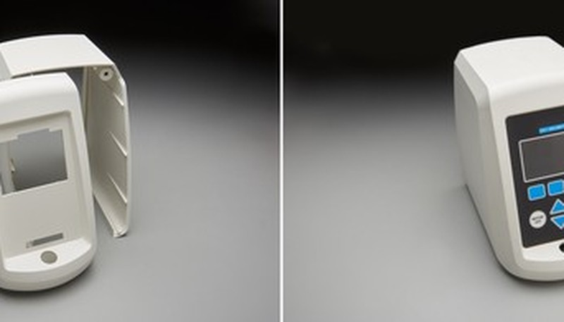
Electronics housings for servers, telecom equipment, and consumer devices often specify flame-retardant PC grades meeting UL 94 V-0 rating at 1.5 mm wall thickness. These grades incorporate non-halogenated flame retardants that maintain PC’s transparency while meeting fire safety standards in enclosed electrical environments.
Construction and architectural applications use polycarbonate for safety glazing, skylights, and vandal-resistant barriers. Multi-wall extruded PC panels dominate the skylight market, while injection-molded PC components serve as connector clips, glazing beads, and structural brackets that benefit from the material’s combination of stiffness, toughness, and outdoor durability.
| Przemysł | Typical Parts | Key PC Property Used |
|---|---|---|
| Motoryzacja | Headlamp lenses, sunroof panels | Optical clarity + impact |
| Medyczny | Surgical handles, oxygenator housings | Sterilization resistance |
| Elektronika | Phone cases, laptop bezels | Impact + flame retardancy |
| Budowa | Safety glazing, skylights | Weatherability + strength |
| Oświetlenie | LED diffusers, light guides | Light transmittance |
| Safety Equipment | Riot shields, face shields | Ballistic impact rating |
ZetarMold processes polycarbonate for customers across all six of these industries. Our facility operates 47 injection molding machines ranging from 30 to 1,600 tons clamping force, with dedicated clean-room capable machines for medical and optical applications. We maintain material traceability from resin lot to finished part for customers requiring ISO 13485 documentation.
Safety equipment manufacturers rely on polycarbonate for riot shields, ballistic-rated face visors, and industrial safety goggles. PC’s ability to absorb high-velocity impacts without shattering—rated to NIJ Level IIIA in laminated configurations—makes it the only practical transparent material for personal protective equipment where failure means serious injury.
The LED lighting industry has adopted polycarbonate as the standard material for light diffusers and optical lenses. PC’s high refractive index (1.586) combined with excellent moldability allows complex freeform lens geometries that direct and distribute light precisely—impossible to achieve with glass lenses at comparable cost for high-volume production.
Frequently Asked Questions About Polycarbonate Injection Molding?
Jaka temperatura jest potrzebna do wtryskiwania poliwęglanu?
Polycarbonate injection molding requires barrel temperatures between 280°C and 320°C, with mold temperatures of 80–120°C. The exact temperature depends on part geometry, wall thickness, and the specific PC grade being processed. Thin-wall parts with thickness under 1.5 mm typically require the higher end of the barrel temperature range and mold temperatures above 100°C to achieve complete cavity fill without excessive injection pressure. Glass-fiber reinforced PC grades generally process at 10–20°C higher barrel temperatures than unfilled grades. Always consult the resin manufacturer’s processing data sheet for grade-specific temperature recommendations to avoid thermal degradation or incomplete filling.
Czy poliwęglan można poddać recyklingowi po formowaniu wtryskowym?
Yes, polycarbonate can be ground into granules and reprocessed as regrind material blended with virgin resin. However, each reprocessing cycle reduces impact strength by 5–8% due to thermal degradation and polymer chain scission that occurs at the high processing temperatures required for PC. Industry best practice limits regrind content to 20% blended with virgin resin for parts requiring full mechanical performance and optical clarity. For non-critical applications such as internal brackets, spacers, or structural parts where transparency is not required, higher regrind percentages up to 40% are acceptable. All regrind material should be re-dried at 120°C for a minimum of 2 hours before reprocessing to prevent moisture-related defects.
Dlaczego poliwęglan żółknie podczas formowania?
Yellowing in polycarbonate occurs when melt temperature exceeds 340°C or when residence time in the barrel exceeds 8 minutes at normal processing temperatures. Both conditions cause thermal oxidation of the bisphenol-A polymer backbone, creating chromophore groups that absorb blue wavelengths of light and shift the transmitted color toward yellow. Moisture contamination above 0.02% accelerates yellowing because hydrolysis at melt temperature generates free phenol groups that act as additional chromophores. Prevention requires proper material drying to below 0.02% moisture, controlled barrel temperatures within the recommended 280–320°C range, correctly sized barrel-to-shot ratios maintaining 50–75% barrel utilization, and purging the barrel with clean material before any production stoppage exceeding 10 minutes.
Czy poliwęglan jest bezpieczny do kontaktu z żywnością?
Polycarbonate meets FDA 21 CFR 177.1580 and EU Regulation 10/2011 food contact requirements when manufactured from approved BPA-based or BPA-free grades with proper processing and documentation. However, concern about bisphenol-A leaching under high-temperature or acidic conditions has driven significant growth in BPA-free alternatives such as Tritan copolyester for reusable food containers, water bottles, and baby products. For single-use medical devices, laboratory equipment, and industrial food processing components where chemical resistance and sterilization capability are priorities, standard polycarbonate remains widely accepted and regulatory-compliant. Always verify the specific grade’s food contact compliance certificate and migration test results before committing to production for any food contact application.
Jak poliwęglan wypada w porównaniu z akrylem w zastosowaniach optycznych?
Polycarbonate and acrylic (PMMA) both offer over 90% light transmittance through clear sections, but their mechanical behavior differs dramatically in impact performance. Acrylic is approximately 30 times more brittle than polycarbonate, shattering at impact energies that PC absorbs without visible damage or permanent deformation. Acrylic offers superior scratch resistance (pencil hardness 3H versus PC’s 2B) and better UV stability without requiring stabilizer additives, making it preferred for indoor display cases and signage. For applications requiring both optical clarity and impact resistance—such as safety shields, automotive headlamp lenses, and protective equipment visors—polycarbonate is the only viable single-material solution. Hard coating brings PC’s scratch resistance to 3H–4H, closing acrylic’s surface hardness advantage.
Czy poliwęglan wymaga wygrzewania po wtrysku?
Polycarbonate does not require annealing for every part, but it is strongly recommended for components that will see chemical exposure, tight assembly loads, or long-term outdoor service. A typical annealing cycle of 125–135°C for 1–4 hours can reduce molded-in stress by 60–85%, which greatly lowers the risk of environmental stress cracking around bosses, snap fits, and gate areas. In production, the parts most likely to benefit are transparent covers, medical housings, and structural parts thicker than 3 mm. If the application includes solvents, adhesives, ultrasonic welding, or high clamp loads, annealing should be treated as a process requirement rather than an optional finishing step.
References & Sources
- Covestro. Makrolon® Polycarbonate Technical Data. solutions.covestro.com/en/brands/makrolon — PC optical transmittance (92%), impact strength, glass transition temperature (147°C).
- SABIC. LEXAN™ Resin 101 Datasheet. nexeoplastics.com — Refractive index (1.586, ASTM D542), drying temperature (120°C, 3–4 hr), processing parameters.
- Covestro. Annealing of Molded Makrolon® Parts. solutions.covestro.com — Annealing parameters (125–135°C, 1–4 hr) and stress reduction for PC.
- Baiwe Molding. PC Injection Molding Processing Guide. baiwemolding.com — Melt temperature 280–320°C, mold temperature 80–120°C, injection pressure ranges.
- Underwriters Laboratories. UL 94 Flammability Standard. en.wikipedia.org/wiki/UL_94 — V-0 and V-2 flame rating definitions for polycarbonate.
- Wikipedia. Polycarbonate. en.wikipedia.org/wiki/Polycarbonate — Density (1.20 g/cm³), thermal expansion, glass transition temperature (~147°C).
- YourPCB. produkcja tworzyw sztucznych yourpcb.com — EMI shielding: conductive paint 40–60 dB, vacuum metallization 60–80 dB.
-
polycarbonate: Polycarbonate (PC) is an amorphous engineering thermoplastic characterized by exceptional impact strength (notched Izod: 600–900 J/m), optical clarity up to 92% light transmittance, and a glass transition temperature of approximately 147°C. ↩
-
mold flow analysis: Mold flow analysis is a computer simulation technique used to predict how molten plastic fills a mold cavity, identifying potential defects such as air traps, weld lines, and uneven shrinkage before tooling is manufactured. ↩
-
weld lines: A weld line is a visible seam formed where two separate melt fronts meet and fuse inside the mold cavity, often reducing local mechanical strength by 10–25% depending on material and processing conditions. ↩


