 Overslaan naar inhoud

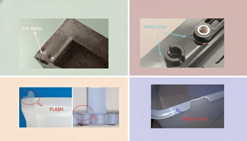
- Sink marks, warping, weld lines, flash, and short shots are the most common injection molding defects.
- Most defects result from non-uniform wall thickness, incorrect process parameters, or inadequate venting.
- Material contamination and moisture are leading causes of surface defects including splay, delamination, and discoloration.
- Mold flow simulation identifies defect-prone areas before tooling begins, reducing trial-and-error corrections.
- Each defect has a root cause hierarchy: design, material, process, and tooling—address in that order.
What Are the Most Common Injection Molding Defects?
The ten most common injection molding defects are: sink marks (localized surface depressions), warping2 (dimensional distortion), weld lines1 (flow-front merge seams), flash (excess plastic at parting line), short shot3s (incomplete fill), burn marks (thermal degradation), splay or silver streaks (gas/moisture on surface), delamination4 (surface layer separation), jetting (snake-like flow mark), and voids (internal bubbles). Each has a distinct root cause and correction pathway.
In our factory, we track defect occurrence rates across all 47 injection molding machines. Sink marks and warping together account for over 40% of first-article failures. Flash and short shots together account for another 25%. Understanding the root cause hierarchy—design, material, process, tooling—is the fastest path to resolution. Design-caused defects cannot be fixed by adjusting machine parameters alone.
What Causes Sink Marks and How Are They Prevented?
Sink marks form when the outer skin of a molded part solidifies while the interior remains molten. As the core cools and contracts, it pulls the surface inward, creating a visible depression. The primary cause is non-uniform wall thickness: sections thicker than 4 mm, ribs thicker than 60% of the adjoining wall, or bosses with wall-to-outer-diameter ratios above 60% are most susceptible.
Prevention strategies operate at three levels. Design: core out thick sections, keep ribs at 50–60% of the nominal wall, and use radiused transitions between thickness changes. Process: increase packing pressure (typically 60–80% of injection pressure), extend pack and hold time until the gate freezes, and reduce melt temperature to minimize volumetric shrinkage. Tooling: add a vent or gas-assist channel in the thick section, or reposition the gate to the thick section so packing pressure reaches it before the thin sections freeze.
The most reliable prevention is design modification before tooling. Once a sink-prone thick section is machined into the mold, corrections require either process optimization (which may only partially eliminate the defect) or mold modification (adding steel to core out the thick section—expensive and time-consuming). In our factory, we flag all wall sections above 4 mm during DFM review and require customer approval before proceeding.
Gas-assist injection molding offers an alternative solution for structurally thick sections that cannot be cored out for functional reasons. A nitrogen gas channel is injected into the thick section after the initial shot, creating a hollow core that eliminates the volume of material that would otherwise shrink and form a sink. This technique adds tooling and equipment cost but enables thick-section parts that would be impossible to produce with standard injection molding.
“Sink marks are primarily caused by non-uniform wall thickness in the part design.”Echt
When walls exceed 4 mm or rib thicknesses exceed 60% of the nominal wall, the core material volume contracts during cooling more than the outer skin can compensate for. The result is an inward surface depression—a sink mark—directly above the thick section.
“Increasing injection pressure alone can reliably eliminate sink marks.”Vals
Increasing injection pressure addresses only part of the issue. Sink marks caused by thick sections require packing and hold pressure to be effective—but only while the gate remains open. Once the gate freezes, no additional pressure can reach the thick section. Design modification is the only permanent solution.
What Causes Warping and How Is It Corrected?
Warping occurs when cooling rate variation across the part exceeds 15°C, generating differential internal stresses that manifest as non-planar distortion after ejection. Primary causes include: non-uniform wall thickness creating unequal shrinkage rates, asymmetric cooling (one mold half hotter than the other), semi-crystalline resins with high anisotropic shrinkage (PP, nylon, POM), and ejection of parts before they reach thermal equilibrium.
Correction follows a systematic approach. First, verify wall thickness uniformity—walls varying more than 25% from nominal generate differential shrinkage that causes warping regardless of process settings. Second, balance mold cooling: our factory typically requires cooling channel temperature differential between core and cavity of ≤ 5°C. Third, extend cooling time until the part reaches ejection temperature (typically Tg − 30°C for amorphous resins). Fourth, use analyse van de matrijsstroming to simulate warpage and identify the dominant cause before modifying the mold.
Fiber orientation in glass-filled resins creates a particularly challenging warping mode. When GF nylon flows through a gate, fibers align in the flow direction. Perpendicular to flow, shrinkage is 2–3× higher than in-flow shrinkage, causing the part to curl. Correcting this requires balanced gating (multiple gates to minimize unidirectional flow), modified mold temperature settings, or switching to a lower-fiber-content or mineral-filled grade.
Part fixturing immediately after ejection is a temporary workaround used when design modifications are impractical. The part is held in a fixture at elevated temperature (50–80°C) until stresses relax, then cooled under constraint. This adds 30–120 seconds per part cycle and requires fixture tooling, but can achieve acceptable flatness for moderately warped parts while permanent design corrections are implemented.
What Causes Flash, Short Shots, and Burn Marks?
Flash is thin excess plastic at the parting line or around ejector pins, caused by: injection pressure exceeding the clamping force for the projected area; worn or damaged parting surfaces with gaps > 0.02 mm; insufficient clamping tonnage (rule: 2–5 tons/in² of projected area); or processing at excessively high melt temperature or injection speed. Flash is a dimensional and cosmetic defect that requires trimming and indicates process or tooling problems.
Short shots are incomplete fills where one or more sections of the cavity do not fill. Causes include: insufficient shot size (check screw forward position at end of injection); gate freeze-off before cavity fills (gate undersized); insufficient injection pressure or speed; blocked vents preventing air escape; or cold melt plugging the flow path. Systematic root-cause analysis using a short-shot study (progressive fill from 20% to 100%) reveals where and why filling stops.
Burn marks (brown or black discoloration at end-of-fill areas) result from adiabatic compression of trapped air as the melt front converges. The trapped air reaches temperatures exceeding 300°C, scorching the plastic. Correction: add or open vents (0.02–0.05 mm depth, 6–8 mm wide) at burn mark locations. If vents are already present, verify they are not plugged with degraded material. Reducing injection speed at the last 10–20% of fill also helps by slowing the melt front and allowing air more time to escape.
“Burn marks in injection-molded parts are caused by trapped air that heats to combustion temperatures.”Echt
When the melt front traps air against the mold wall, rapid compression of the air raises its temperature above 300°C through adiabatic heating. This scorches the resin in contact with the hot trapped air, leaving brown or black discoloration. Adding vents at burn locations provides an escape path for the compressed air.
“Flash defects can only be corrected by rebuilding the mold.”Vals
Flash has multiple causes, many correctable without mold work: reducing injection pressure, lowering melt temperature, increasing clamping force, or extending pack time. Only when parting surface wear or damage is the root cause is mold repair required. Process optimization often eliminates flash without tooling changes.
How Are Weld Lines, Delamination, and Splay Defects Addressed?
Weld lines form where two melt flow fronts meet. They are unavoidable in parts with holes, multiple gates, or complex flow paths, but their severity can be minimized. The strength reduction at a weld line is 10–30% for unfilled resins and up to 50% for glass-filled grades. To reduce weld line impact: increase melt and mold temperature to improve flow-front bonding; reposition or add gates to relocate weld lines away from structural features; increase injection speed at the convergence zone; or add a vent or overflow tab at the weld line location to purge cold material.
Delamination presents as thin surface layers peeling off the part, caused by contaminated material (incompatible resin mixed in), material degradation from excessive residence time, or excessive shear at the gate. Corrective action: purge machine thoroughly between material changes; verify material lot documentation for contamination; reduce injection speed through the gate; and check barrel temperature profile for overheating zones. In our factory, material contamination incidents are traced to inadequate hopper cleaning during color or grade changes—a protocol issue, not a process issue.
Splay (silver streaks) appears as shiny silver or white streaks on the surface radiating from the gate. The two primary causes are moisture (from inadequately dried hygroscopic resins like nylon, PC, ABS) and gas (from volatile additives or thermal degradation). Nylon absorbs 2–3% moisture and must be dried to < 0.2% moisture before processing; PC requires drying to < 0.02% at 120°C for 4 hours minimum. Our factory uses automated material drying stations with dew point monitoring to prevent splay from moisture-related causes.
Injection Molding Defect Summary Table
| Defect | Primary Cause | Correction |
|---|---|---|
| Als het materiaal bevriest voordat het vult, verhoog dan de injectiesnelheid (vulsnelheid). | Thick walls, low pack pressure | Core out thick sections, increase hold |
| Scheeftrekken | Uneven cooling, thick walls | Uniform cooling, balanced wall thickness |
| Laslijnen | Multiple flow fronts | Reposition gate, increase temp/speed |
| Flash | Low clamp, worn parting surface | Increase clamp tonnage, repair parting |
| Korte opname | Insufficient fill, blocked vent | Increase shot size, open vents |
| Ontwerpen voor spuitgieten draait fundamenteel om het begrijpen van hoe gesmolten plastic zich gedraagt in een stalen holte. Elke ontwerpbeslissing — wanddikte, ontlophoeken, ribben, plaatsing van de ingang, materiaalkeuze — heeft een direct, meetbaar effect op de onderdeelkwaliteit, de cyclustijd en de gereedschapskosten. | Trapped air compression | Add vents, reduce final fill speed |
| Splay | Moisture, gas in material | Dry material, check temperature profile |
| Delamination | Material contamination | Purge machine, verify material purity |
| Jetting | Gate undersized, melt too fast | Enlarge gate, reduce injection speed |
| Leegtes | High shrinkage, low pack | Increase pack pressure, reduce wall |
In our factory, this defect matrix is posted at every molding machine. Operators trained to identify symptoms and refer to the root-cause hierarchy prevent minor defects from escalating into full production rejections. Early detection—within the first 10 shots of a production run—is the most cost-effective point of intervention.
Veelgestelde vragen
Veelgestelde vragen
What are the most common injection molding defects?
The most common injection molding defects, ranked by frequency in production environments, are: (1) sink marks from thick-section shrinkage; (2) warping from differential cooling and shrinkage; (3) weld lines at flow-front convergence points; (4) flash at parting lines or ejector pins; (5) short shots from insufficient fill; (6) burn marks from trapped air; (7) splay or silver streaks from moisture or gas; (8) delamination from contamination; (9) jetting from improper gate sizing; (10) voids from internal shrinkage. Sink marks and warping dominate first-article failures because they are primarily design-driven—process adjustments provide limited correction once the mold is cut.
How can weld lines be reduced in injection-molded parts?
Weld line reduction involves controlling where flow fronts meet and improving their bonding when they do. To minimize weld lines: (1) use single-gate designs to eliminate flow-front convergence entirely where part geometry allows; (2) position gates so flow fronts converge at non-structural or non-visible locations; (3) increase melt temperature to improve molecular diffusion at the weld; (4) increase mold temperature to slow skin formation and allow more time for molecular bonding at the weld interface; (5) increase injection speed to keep the melt hotter at convergence; (6) add overflow wells or vents at weld line locations to purge degraded cold material; (7) use mold flow simulation to predict weld line positions for different gate configurations before cutting steel.
Why do injection molded parts warp after ejection?
Warping results from non-uniform internal stresses that cause differential dimensional change after the part is released from the mold constraint. The root causes are: (1) non-uniform wall thickness creating unequal shrinkage rates across the part; (2) asymmetric mold cooling where one face cools faster than the opposite face; (3) semi-crystalline resins (PP, nylon, POM) that exhibit higher and more anisotropic shrinkage than amorphous resins; (4) fiber orientation in filled grades creating directional shrinkage; (5) premature ejection before the part reaches thermal equilibrium with the mold. Correction requires addressing the dominant root cause—usually design (wall uniformity) or cooling (channel balance)—rather than adjusting injection parameters.
How is flash prevented in injection molding?
Flash prevention requires adequate clamping force and proper parting surface maintenance. Clamping force must exceed the cavity pressure multiplied by the projected area—the standard rule is 2–5 tons per square inch of projected area, with amorphous resins at the lower end and filled or high-viscosity resins at the upper end. Beyond adequate tonnage, preventive measures include: maintaining parting surface flatness within 0.01 mm during mold qualification; replacing worn ejector pin bushings that develop radial gaps; reducing injection pressure and melt temperature within acceptable fill windows; and scheduling periodic mold inspection every 50,000–100,000 shots to check parting surface condition before flash becomes a production problem.
What causes splay (silver streaks) in injection-molded parts?
Splay appears as silver or white streaks on the part surface radiating from the gate, and results from gas or steam being trapped in the melt stream. Moisture splay occurs when hygroscopic resins (nylon, PC, ABS, PET) are processed with moisture content above specification—typically above 0.1–0.3% by weight. The moisture flashes to steam at melt temperatures, creating the characteristic silver streaks. Solution: dry material to specification in a hopper dryer or conveyor dryer with monitored dew point. Gas splay from thermal degradation occurs when barrel temperature is too high or residence time is too long, generating volatile degradation products. Reduce barrel setpoints and purge frequently if processing at extended barrel residence times.
How does mold flow analysis help prevent injection molding defects?
Mold flow analysis simulates the injection molding process virtually before any steel is cut, predicting defect locations and process windows. It identifies: weld line positions for different gate configurations; air trap locations requiring vents; fill pressure distribution revealing areas at risk for short shots; cooling uniformity predicting warpage magnitude and direction; and shear stress levels at gates flagging potential degradation or jetting. By comparing multiple gate positions, wall thickness options, and runner layouts in simulation, engineers select designs that minimize defect risk. In our factory, mandatory mold flow analysis for all new tools reduces T1 trial revision cycles from an average of 3 to under 1.5, saving weeks of development time and thousands of dollars in mold modifications.
-
weld lines: Weld lines refers to visible seams that form in injection-molded parts where two separate melt flow fronts converge and fail to fully intermix, creating a plane of reduced strength. ↩
-
warping: Warping is a dimensional distortion defect defined as non-planar deformation of an injection-molded part caused by differential internal stresses from uneven cooling or inconsistent wall thickness. ↩
-
short shot: Short shot refers to an incomplete injection-molded part that occurs when molten plastic fails to fill the entire mold cavity before solidifying, leaving unfilled regions. ↩
-
delamination: Delamination is a surface defect defined as the separation of thin layers on an injection-molded part surface, caused by contamination, moisture, or incompatible material mixing. ↩


