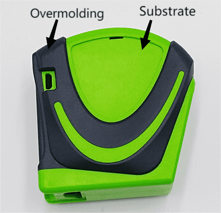
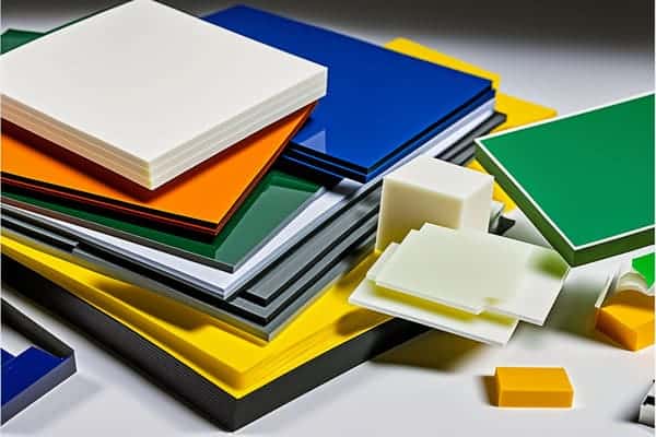
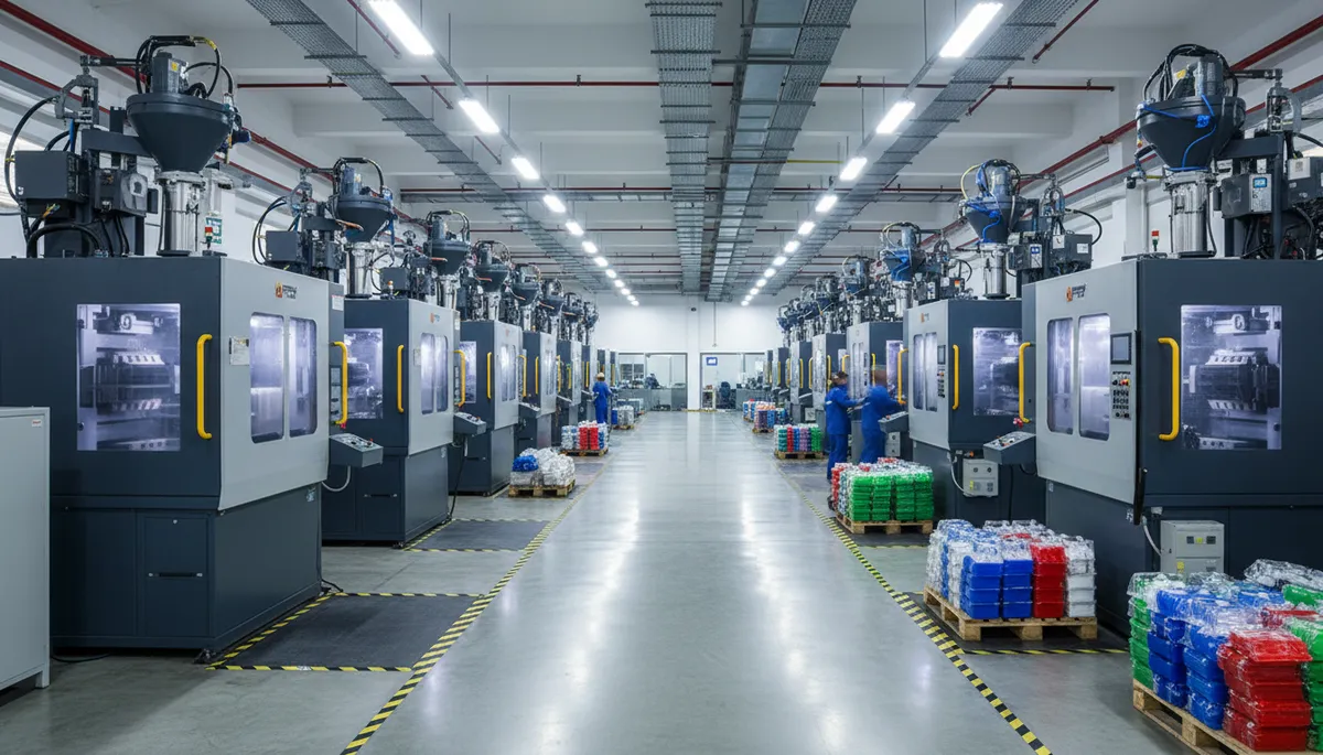
- Overmolding verbindt twee verschillende materialen in één onderdeel, meestal een rigide substraat (ABS, PC, nylon) bedekt met een zacht thermoplastisch elastomeer (TPE), waardoor assemblage stappen met 40-60% worden verminderd.
- Materiaalcompatibiliteit is de belangrijkste kritieke succesfactor: het substraat moet een hoger smeltpunt hebben dan het overmoldingmateriaal, en chemische binding vereist overeenkomende oplosbaarheidsparameters binnen 2 (cal/cm3)^0,5.
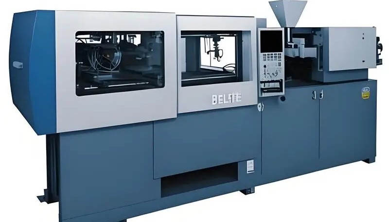
- Twee-schots overmolding op een roterende pers levert cyclustijden op van 25-45 seconden per onderdeel, terwijl pick-and-place overmolding 10-15 seconden toevoegt voor substraatoverdracht maar minder kapitaalinvestering vereist.
- De wanddikte van de overmatrijslaag moet 1,0-3,0 mm zijn voor een adequate vulling en hechting, met een minimum van 0,5 mm op elk punt om kortschieten te voorkomen.
- Veelvoorkomende defecten zijn onder meer delaminatie (verbindingsfalen), flash op het substraat-overmoulding grensvlak en substraatvervorming door injectiedruk van de overmoulding die 40 MPa overschrijdt.
Wat is overspuiten en hoe werkt het?
Overmolding is een tweestaps-spuitgietproces waarbij een tweede materiaal—doorgaans een zacht thermoplastisch elastomeer1—over een vooraf gevormd hard substraat wordt gehecht, zodat in één productiebewerking één onderdeel uit meerdere materialen ontstaat. Het proces elimineert handmatige montage, lijmverbindingen en mechanische bevestigingsmiddelen die kosten, faalpunten en productietijd aan producten uit meerdere materialen toevoegen.
Het substraat wordt eerst gevormd met standaard spuitgietparameters voor de basis hars. Na gedeeltelijke of volledige afkoeling wordt het substraat overgebracht naar een tweede holte (pick-and-place methode) of geroteerd in positie op een pers met meerdere stations (twee-injectie methode). Het overmatrijsmateriaal wordt vervolgens over het substraat geïnjecteerd, waarbij het hecht via chemische adhesie, mechanische vergrendeling, of beide.
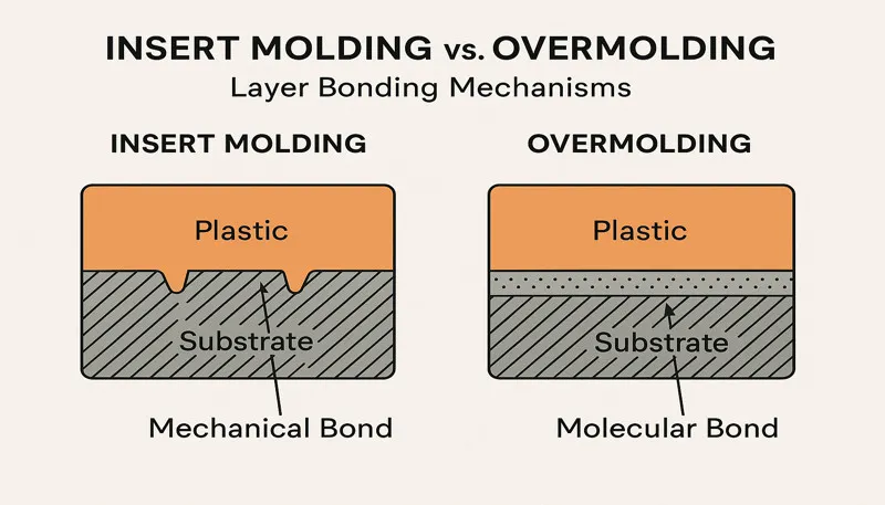
Chemische binding treedt op wanneer het overmoldingmateriaal het substraatoppervlak gedeeltelijk opnieuw smelt, waardoor moleculaire verstrengeling aan het grensvlak ontstaat. Dit mechanisme vereist compatibele polymeersamenstellingen—thermoplastisch elastomeer over ABS bereikt een hechtsterkte van 150–300 N in peeltesten, terwijl incompatibele paren zoals TPE over polyetheen bijna geen hechting opleveren zonder mechanische kenmerken.
| Methode | Cyclustijd | Kapitaalkosten | Beste voor |
|---|---|---|---|
| Two-shot (roterende plaat) | 25–45 sec | $150K–$400K | Productie in grote volumes (>100K onderdelen/jaar) |
| Pick-and-place (overdracht) | 35–60 seconden | $80K–$200K | Middelgrote volumes, complexe substraten |
| Multi-shot (3+ materialen) | 40–70 seconden | $300K–$600K | Meerkleurige of multi-hardheid onderdelen |
| Over-insert hybride | 30–50 seconden | $100K–$250K | Metaalsubstraat + kunststof overmoulding |
De keuze tussen two-shot en pick-and-place hangt af van productievolume en onderdeelcomplexiteit. Two-shot persen met roterende platen elimineren overdrachttijd en zorgen voor een nauwkeuriger positietolerantie (±0,05 mm) tussen substraat en overmoulding. Pick-and-place methoden gebruiken twee afzonderlijke single-shot machines, wat meer flexibiliteit biedt voor substraatgeometrieën die niet tussen stations kunnen roteren.
Succesvol overmolden vereist nauwkeurige beheersing van drie kritische parameters: de oppervlaktetemperatuur van het substraat op het moment van de overmoldinjectie (idealiter 40–80°C boven omgevingstemperatuur), de smelttemperatuur van het overmoldmateriaal (binnen het door de materiaalleverancier aanbevolen venster) en de injectiedruk (doorgaans 30–80 MPa, afhankelijk van wanddikte en vloeiweg). Afwijking van een parameter beïnvloedt rechtstreeks de hechtsterkte en onderdeelkwaliteit.

Welke materialen zijn compatibel voor overmatrijzen?
Materiaalcompatibiliteit bepaalt 80% van het succes of falen van overmatrijzen, waarbij TPE-op-ABS en TPE-op-PC de twee meest betrouwbare combinaties zijn in de commerciële productie. Het substraatmateriaal moet een smelttemperatuur hebben die minstens 40°C hoger is dan het overmatrijsmateriaal om vervorming van het substraat tijdens de tweede injectie te voorkomen—ABS (smeltpunt 220–260°C) gecombineerd met TPE (180–220°C) voldoet aan deze eis met een comfortabele veiligheidsmarge.
De chemische hechtingssterkte hangt af van de overeenkomst in oplosbaarheidsparameters tussen de twee polymeren. Materialen met oplosbaarheidsparameters binnen 2 (cal/cm³)⁰·⁵ van elkaar vormen sterke chemische bindingen. Styreen-TPE (op SEBS-basis) hecht goed aan ABS en polystyreen omdat alle drie een vergelijkbare styreenchemie hebben. Polyester-TPE hecht aan PBT en PC via ester-uitwisselingsreacties op het grensvlak.
| Substraat | Compatibele Overmoulding | Type hechting | Peelsterkte (N) |
|---|---|---|---|
| ABS | TPE (op SEBS-basis) | Chemisch + mechanisch | 150–300 |
| PC | TPE (polyester-gebaseerd) | Chemisch | 120–250 |
| PA6/PA66 (polyamide) | TPE (op polyamidebasis) | Chemisch | 100–200 |
| PP | TPE (PP-gebaseerd, TPV) | Chemisch | 80–150 |
| POM (acetaal) | TPE (elk) | Alleen mechanisch | 30–60 |
| HDPE | TPE (elk) | Alleen mechanisch | 20–50 |
| ISO 10993: | TPE (SEBS of polyester) | Chemisch | 130–270 |
Wanneer chemische hechting onmogelijk is—zoals bij substraten van POM, HDPE en PEEK—biedt mechanische verankering de enige betrouwbare verbinding. Doorvoergaten, ondersnijdingen, groeven en gestructureerde substraatoppervlakken houden het overmoldmateriaal fysiek vast. Deze kenmerken moeten diep genoeg zijn (minimaal 0.3 mm) om de verwachte bedrijfsbelasting te weerstaan; hun onderlinge afstand bepaalt hoe gelijkmatig de verbinding spanning over het grensvlak verdeelt.
Overspuiten met silicone is een bijzonder geval waarvoor een primer of plasmabehandeling van het substraatoppervlak nodig is. Vloeibaar siliconenrubber (LSR) hecht zonder oppervlakteactivering niet chemisch aan thermoplasten. Hechting met primer voegt een processtap toe, maar bereikt hechtsterktes van 80–150 N. Dit is geschikt voor afdichtingen van medische hulpmiddelen, waterdichte pakkingen en automotive connectoren die worden blootgesteld aan temperaturen van -40°C tot +200°C.
De Shore-hardheid van de overspuitlaag bepaalt hoe het afgewerkte onderdeel aanvoelt. Shore A 40–60 geeft een zachte, dempende grip die de voorkeur heeft voor handgereedschap en tandenborstels. Shore A 70–85 biedt een steviger oppervlak dat geschikt is voor elektronicabehuizingen en bedieningselementen in auto’s. Voor de juiste hardheidskeuze moet gebruikerscomfort worden afgewogen tegen slijtvastheid: zachtere materialen slijten sneller bij herhaald schurend contact.
Kleurafstemming tussen substraat en overmold vereist ook aandacht voor het materiaal. Doorschijnende TPE-overmolds laten de substraatkleur doorschijnen, waardoor kleureffecten met één materiaal mogelijk zijn zonder lakken. Ondoorzichtige TPE-soorten bedekken het substraat volledig, wat de voorkeur heeft bij een inconsistente substraatkleur (gerecyclede hars, mineraalgevulde compounds). Meerkleurig overmolden met opeenvolgende shots in verschillende TPE-kleuren creëert merkspecifieke patronen—zoals de kenmerkende tweekleurige handgrepen van elektrisch gereedschap—zonder decoratie na het spuitgieten.

"Omspuiten van TPE op ABS bereikt een chemische hechtsterkte van 150–300 N zonder oppervlakteprimers of mechanische kenmerken."True
TPE op SEBS-basis en ABS hebben een styreenchemie gemeen, waardoor moleculaire ketens op het grensvlak kunnen verstrengelen wanneer de oppervlaktetemperatuur van het substraat tijdens het overspuiten hoger is dan 60°C. Deze chemische compatibiliteit maakt TPE/ABS de meest gebruikte overspuitcombinatie in consumentenproducten, van handgrepen van elektrisch gereedschap tot apparaten voor persoonlijke verzorging.
"Elke twee kunststoffen kunnen samen worden overmold zolang de spuitparameters correct worden geoptimaliseerd."False
De materiaalchemie beperkt de compatibiliteit bij overmolding fundamenteel. POM, HDPE en PEEK hebben een lage oppervlakte-energie en apolaire moleculaire structuren die chemische hechting met elke TPE verhinderen, ongeacht procesoptimalisatie. Deze substraten vereisen mechanische vergrendelingselementen in de onderdeelgeometrie; geen enkele aanpassing van temperatuur of druk kan een chemische verbinding creëren als de polymeerchemie onverenigbaar is.
Wat Zijn de Belangrijkste Ontwerprichtlijnen voor Overmolding Onderdelen?
Een overmold-wanddikte van 1.0–3.0 mm is het optimale bereik voor volledige vulling van de holte, voldoende hechting en een aanvaardbare cyclustijd. Onder 1.0 mm bevriest de smelt voordat het einde van de vulling wordt bereikt, waardoor onvolledige vulling en zwakke hechting ontstaan. Boven 3.0 mm neemt de koeltijd exponentieel toe—een overmoldlaag van 4.0 mm vereist 60% meer koeltijd dan een laag van 2.5 mm, wat 8–12 seconden per cyclus toevoegt.
Het afsluitontwerp bij de overgang tussen substraat en overmolding voorkomt braamvorming—de dunne materiaalfilm die bij de materiaalovergang tussen de matrijsoppervlakken wordt geperst. Een staal-op-staalafsluiting met een speling van 0.01–0.02 mm en een interferentiehoek van 3–5° zorgt gedurende meer dan 500,000 cycli voor een betrouwbare afdichting. Mes-en-groefontwerpen bieden een nog betere beheersing van braamvorming, maar tegen hogere gereedschapskosten.
| Parameterwaarde | Aanbevolen bereik | Gevolg van overtreding |
|---|---|---|
| Wanddikte van de overspuiting | 1.0–3.0 mm | Onvolledige vulling (onder 1.0) of lange cycli (boven 3.0) |
| Speling van de afsluiting | 0.01–0.02 mm | Braamvorming op het grensvlak (>0.03 mm) |
| Lossingshoek van het substraat | 1.5–3.0° | Uitwerpschade (onder 1.0°) |
| Diepte van de mechanische vergrendeling | minimaal ≥0.3 mm | Hechtingsbreuk onder belasting (onder 0.2 mm) |
| Verhouding van de vloeilengte van de aanspuiting tot het verste uiteinde | ≤100:1 | Onvolledige vulling of laslijnen |
| Oppervlakteruwheid van het substraat | Ra 1.6–6.3 μm | Slechte hechting (onder Ra 0.8) |
Voor de plaatsing van de aanspuiting bij de overspuitshot gelden andere regels dan bij spuitgieten met één materiaal. De aanspuiting moet de smeltstroom langs de langste afmeting van het overspuitgebied leiden en het stroompad van de aanspuiting tot het verste punt mag een verhouding van 100:1 tussen stroomlengte en wanddikte niet overschrijden. Waaier- en filmaanspuitingen verdelen de smelt gelijkmatiger dan puntaanspuitingen en verminderen lasnaden die zichtbare cosmetische defecten en potentiële zwakke plekken in de hechting veroorzaken.
Voorbehandeling van het substraat beïnvloedt de hechting sterk. Een ruwheid van Ra 1.6–6.3 μm biedt optimale micromechanische verankering. Sterk gepolijste substraten (Ra onder 0.8 μm) hechten minder door gebrek aan grip. EDM-vonkerosie of chemisch etsen kan de afpelsterkte met 30–50% verhogen ten opzichte van gladde oppervlakken.
Een grondige DFM5-beoordeling vóór de gereedschapsbouw brengt ontwerpproblemen aan het licht die na het snijden van het matrijsstaal duur zijn om te verhelpen. Veelvoorkomende DFM-bevindingen bij overmolding zijn onvoldoende lossingshoek van het substraat (met uitwerpschade als gevolg), te dunne overmoldsecties voor betrouwbare vulling en afsluitgeometrieën die na 50.000 cycli braamvorming veroorzaken. Door deze bevindingen in de ontwerpfase op te lossen, wordt per project $5.000–$15.000 aan matrijsaanpassingen bespaard.

Wat Zijn de Meest Voorkomende Overmoulding Defecten en Oplossingen?
Delaminatie — het loskomen van de overspuiting van het substraat — is het meest kritieke defect bij overspuiten. Het treedt op bij 35% van de eerste proefruns wanneer de materiaalcompatibiliteit niet vooraf is gevalideerd. De hoofdoorzaak is altijd onvoldoende hechtsterkte op het grensvlak, hetzij door incompatibele materialen, een lage oppervlaktetemperatuur van het substraat, vervuilde oppervlakken of onvoldoende voorzieningen voor mechanische verankering.
Vervorming van het substraat treedt op wanneer de injectiedruk van de overmolding bij verhoogde temperatuur groter is dan de weerstand van het substraat tegen doorbuiging. Dunwandige substraten (wanddikte minder dan 1.5 mm) zijn bijzonder kwetsbaar: een injectiedruk van 60 MPa kan een ABS-substraat van 1.0 mm met 0.3–0.5 mm doen doorbuigen, waardoor maatfouten en zichtbare cosmetische gebreken ontstaan. Dit defect kan worden voorkomen door de injectiesnelheid en -druk te verlagen of het substraat te ondersteunen met kernvoorzieningen in de matrijs.
| Defect | Hoofdoorzaak | Eerste Oplossing | Preventie |
|---|---|---|---|
| Delaminatie | Incompatibele materialen of koud substraat | Verhoog de voorverwarming van het substraat tot 60–80°C | Valideer de materiaalcombinatie met een pelproef |
| Braamvorming bij de overgang | Versleten afsluiting of te hoge sluitdruk | Afsluitvlakken opnieuw verspanen | Ontwerp een tand-en-groefafsluiting |
| Onvolledige vulling (omspuiting) | Dunne secties stollen voortijdig | Verhoog de smelttemperatuur met 10–20°C | Herontwerp naar minimale wanddikte van 1,0 mm |
| Substraatvervorming | Injectiedruk te hoog | Vulsnelheid met 20–30% verminderen | Kernondersteuningskenmerken in matrijs toevoegen |
| Laslijnen | Meerdere smeltfronten die samenkomen | Verplaats de ingangspositie | Gebruik sequentiële klep-ingangen |
Flash aan de substraat-overmold interface hoopt zich geleidelijk op naarmate de afsluitoppervlakken slijten door herhaalde matrijsscycli. Nieuwe matrijzen lopen typisch flash-vrij voor 100.000–200.000 cycli, waarna de staal-op-staal contactoppervlakken hun scherpe randen verliezen. Preventief onderhoud omvat het opnieuw frezen van afsluitoppervlakken elke 150.000 cycli en het gebruik van geharde stalen inserts (HRC 52–58) op hoogslijtage afsluitlocaties om onderhoudsintervallen te verlengen tot 400.000+ cycli.
Laslijnen ontstaan waar twee of meer smeltfronten samenkomen tijdens het vullen van de overmould. In tegenstelling tot laslijnen van één materiaal die vooral cosmetisch zijn, kunnen overmouldlaslijnen zones zonder verbinding creëren waar geen van de stromingsfronten het substraat met voldoende druk raakt om hechting te vormen. Sequentieel klep-poorten – waarbij de poorten in een getimede volgorde openen in plaats van gelijktijdig – elimineren convergerende stromingsfronten en produceren onderdelen zonder laslijnen.
Zinkingen aan de substraatzijde tegenover dikke overmoldgedeelten zijn een ander terugkerend probleem. Wanneer de overmoldlaag lokaal 3,0 mm overschrijdt, zorgt de geconcentreerde warmtemassa ervoor dat het substraat opnieuw verzacht en naar binnen krimpt. Het beperken van de overmolddikte tot maximaal 2,5 mm op elke doorsnede, of het toevoegen van koelkanalen direct onder dikke overmoldzones, elimineert substraatzijde zinkingen in 90% van de gevallen.
Kleurvervloeiing treedt op wanneer pigmenten in het overmouldmateriaal migreren naar het substraat gedurende de korte periode waarin beide oppervlakken boven hun verzachtings temperatuur zijn. Dit defect is het meest zichtbaar bij donkere overmoulds op lichte substraten. Het gebruik van TPE-kwaliteiten met ingekapselde pigmentsystemen – waarbij kleurstofdeeltjes zijn opgesloten in polymeermicrosferen – voorkomt migratie zelfs bij verhoogde verwerkingstemperaturen.
"Voorverwarming van het substraat tot 60–80°C vóór het overspuiten verhoogt de hechtsterkte met 40–70% ten opzichte van substraten op kamertemperatuur."True
Een verhoogde substraattemperatuur houdt de grenszone tijdens overmouldcontact boven de glastransitietemperatuur, waardoor polymeerketendiffusie over de grens mogelijk is. Industriële tests op TPE/ABS-paren tonen aan dat de pellsterkte toeneemt van 120 N bij 25°C substraattemperatuur tot 210 N bij 70°C, met afnemende meeropbrengsten boven 90°C waar substraatverweking dimensionaal risico introduceert.
"Defecten bij overmolding kunnen altijd worden verholpen door procesparameters aan te passen zonder het matrijs- of onderdeelontwerp te wijzigen."False
Procesoptimalisering kent grenzen. Delaminatie door incompatibele materialen vereist een materiaalwijziging, geen proceswijziging. Flash door versleten afsluitoppervlakken vereist matrijsreparatie. Korte shots in secties dunner dan 0,5 mm vereisen een ontwerpwijziging om de wanddikte te vergroten. Ongeveer 40% van de overmoldingdefecten in productie vereist matrijs- of ontwerpwijzigingen die niet alleen via procesparameteraanpassing kunnen worden opgelost.
Welke Industrieën Gebruiken Overmolding en Waarom?
Consumentenelektronica vertegenwoordigt 30% van de wereldwijde vraag naar overmoulding, gedreven door de universele behoefte aan zachte grepen, afgedichte behuizingen en meerkleurenesthetiek in smartphones, wearables en elektrisch gereedschap. Een enkele overmouldtelefoonhoes vervangt een driedelige assemblage (harde schaal + rubberen bumper + lijm), wat de fabricagekosten met $0.15–$0.40 per stuk verlaagt bij volumes boven de 500.000.
Medische apparaten vormen het snelst groeiende overmouldsegment, met een jaarlijkse groei van 8–12%. Chirurgische instrumenten vereisen ergonomische grepen met Shore A 50–65 TPE over roestvrij staal of polycarbonaatsubstraten, wat een niet-glijdend houvast biedt in natte chirurgische omgevingen. De overmouldlaag verzegelt ook interne elektronica tegen vochtindringing, waardoor IP67- of IP68-classificaties worden bereikt zonder extra pakkingen of secundaire afdichtingsbewerkingen.
Automobielinterieurcomponenten gebruiken overmoulding uitgebreid voor dashboardschakelaars, stuurwielbedieningen en deurklinken. De overmouldlaag zorgt voor consistente tactiele feedback (Shore A 70–85), UV-bestendigheid (minimaal 1.000 uur xenonboog volgens SAE J2527) en chemische bestendigheid tegen handcrèmes, zonnebrandcrème en schoonmaakmiddelen. Elke overmouldschakelaar elimineert 2–3 assemblage stappen vergeleken met mechanisch bevestigde rubber-op-kunststofalternatieven.
| Industrie | Typische toepassing | Belangrijkste eis | Kostenbesparing versus assemblage |
|---|---|---|---|
| Consumentenelektronica | Telefoonhoesjes, gereedschapshandvatten | Zachte aanvoel, valbescherming | 15–25% per stuk |
| Medische apparaten | Chirurgische instrumenten, medicijntoediening | Biocompatibel, IP67 afgedicht | 20–35% per eenheid |
| Auto-industrie | Schakelaars, knoppen, handgrepen | UV-stabiel, chemisch bestendig | 10–20% per stuk |
| Industriële gereedschappen | Handvatten voor elektrisch gereedschap, trillingsgrepen | Schokabsorptie, vermoeiingsleven | 15–30% per eenheid |
| Persoonlijke verzorging | Tandenborstels, scheermesjes | Zachte grip, vochtbestendig | 25–40% per eenheid |
Industriële elektrische gereedschappen benutten overmolding voor trillingsdemping naast gripcomfort. Een 2,0 mm TPE-overmoldlaag op een nylon gereedschapsbehuizing absorbeert 20–35% van de overgedragen trillingsenergie, waardoor de blootstelling van de operator aan hand-armtrillingen onder de dagelijkse actiewaarde van 2,5 m/s² blijft, zoals gespecificeerd in ISO 5349. Dit functionele voordeel rechtvaardigt de €0,30–€0,80 per eenheid kostentoename ten opzichte van kale kunststofbehuizingen.
Persoonlijke verzorgingsproducten - tandenborstels, scheermesjes en haarstylingtools - waren in de jaren 90 pioniers op het gebied van overmoulding in hoge volumes en blijven een ijkpunt voor procesefficiëntie. Moderne tandenborstelproductielijnen overmoulden 4–8 holtematrijzen in cycli van 15 seconden en produceren 40.000–80.000 handgrepen per dag op één pers. De overmould biedt zowel de gripstructuur als de kleuraccent die concurrerende merken in de winkelrekken onderscheidt.
De lucht- en ruimtevaartsector heeft overmoulding overgenomen voor trillingsgedempte montagebeugels en afgedichte connectorbehuizingen die betrouwbaar moeten functioneren van -55°C tot +125°C. Fluoroelastomeer (FKM) overmoulds op PEEK- of PEI-substraten weerstaan vliegtuigbrandstof, hydraulische vloeistof en ontdooimiddelen, terwijl ze de trillingsisolatie bieden die gevoelige avionica beschermt tegen door de motor overgedragen resonantiefrequenties.
Hoe Verhoudt Overmoulding Zich Tot Insert Moulding?
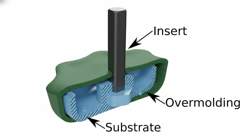
Overmolding en insert molding2 combineren beide meerdere materialen in één onderdeel, maar verschillen in substraattype en procesvolgorde: overmolding verbindt kunststof met kunststof (of kunststof met TPE), terwijl bij insert molding doorgaans metalen onderdelen zoals schroefdraadinserts, elektrische contacten of constructieve verstevigingen in een kunststof lichaam worden ingekapseld.
Het substraat bij overmoulding wordt altijd eerst spuitgegoten - ofwel in dezelfde cyclus (twee-schot) of in een aparte voorafgaande bewerking (pick-and-place). Bij insert moulding is het substraat een voorgevormd onderdeel (gestampt metaal, verspaand messing, kabelboom) dat vóór het inspuiten in de mal wordt geplaatst. Dit onderscheid beïnvloedt het matrijsontwerp: overmouldmatrijzen hebben twee inspuiteenheden en twee holtesets nodig, terwijl insert mouldmatrijzen één inspuiteenheid plus een geautomatiseerd substraatladsysteem nodig hebben.
| Invloedsfactor | Overspuiten | Tussenvoegsel Vormen |
|---|---|---|
| Substraatmateriaal | Spuitgegoten kunststof | Metaal, voorgevormde kunststof, draad |
| Bindingsmechanisme | Chemisch + mechanisch | Mechanische inkapseling |
| Typische cyclustijd | 25–45 sec (tweecomponenten) | 20–40 sec (één cyclus + beladen) |
| Gereedschapskosten | $150K–$400K | $80K–$200K |
| Hechtsterkte | 150–300 N (afpelkracht) | Afhankelijk van de inkapselingsgeometrie |
| Beste toepassing | Softgrip-handgrepen, afgedichte behuizingen | Inzetstukken met schroefdraad, elektrische contacten |
De kostenvergelijking valt uit in het voordeel van inlegspuitgieten voor onderdelen die een metaalfunctie vereisen (schroefdraad, geleidbaarheid, constructieve sterkte) en van overspuiten voor onderdelen die een uiterlijk met meerdere materialen of tactiele eigenschappen vereisen. Een metalen schroefdraadinzetstuk dat in nylon is ingekapseld, kost $0.08–$0.15 minder per onderdeel dan een afzonderlijk gemonteerd inzetstuk met schroefdraad. Een overspoten handgreep met zachte grip kost $0.20–$0.40 minder dan een met lijm bevestigde rubberen huls om een stijve handgreep.
Veel producten combineren beide processen in één onderdeel. De handgreep van een elektrische boormachine gebruikt bijvoorbeeld insert molding om messing draadinzetstukken en elektrische contacten te omsluiten, gevolgd door overmolding voor het soft-touch TPE-gripoppervlak. Deze combinatie levert structurele metaal-kunststofverbindingen en ergonomische kunststof-TPE-oppervlakken in een onderdeel met drie materialen, waarvoor bij conventionele productie 6–8 montagestappen nodig zouden zijn.
Hoe Gaat Zetar Om met Overmolding Projecten?
Het engineeringteam van Zetar voert vóór het snijden van gereedschapsstaal voor elk overmoldingproject een matrijsvulkanalyse3 uit. Zowel de substraatinjectie als de overmoldinjectie wordt gesimuleerd om vulpatronen, temperaturen bij de verbindingslijn en potentiële defectlocaties te voorspellen. Deze dubbele simulatie identificeert de 85% van mogelijke overmoldingproblemen die voortkomen uit keuzes voor materiaal en aanspuitpositie voordat de gereedschapsbouw begint.
Met 47 spuitgietmachines van 50 tot 1,600 ton—waaronder meercomponentenpersen met draaitafels—verwerkt Zetar overmoldingprojecten van prototypeseries van 100 onderdelen tot jaarvolumes boven 1,000,000. De faciliteit heeft speciale apparatuur voor materiaalcompatibiliteit, waaronder pelproefopstellingen die de hechtsterkte tussen substraat en overmolding valideren voordat productiegereedschap wordt gebouwd.
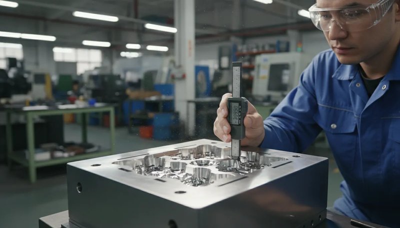
Zetars proces voor het ontwerpen van spuitgietmatrijzen4 omvat optimalisatie van afsluitingen met slijtage-simulatie om onderhoudsintervallen te voorspellen. Zo blijft de productie meer dan 300.000 cycli braamvrij vóór de eerste geplande nabewerking van een afsluiting. Gecombineerd met een first-pass yield van 92% bij overmoldingprojecten vermindert deze aanpak het gebruikelijke aantal van 3–4 matrijsiteraties tot 1–2 en bespaart klanten per project $10.000–$30.000 en 4–8 weken ten opzichte van het sectorgemiddelde.

Veelgestelde Vragen Over Overmoulding?
Wat is het verschil tussen overmolding en two-shot molding?
Overmolding is de brede categorie voor elk proces waarbij het ene materiaal over het andere wordt gehecht. Two-shot molding is een specifieke overmoldingmethode waarbij beide materialen in dezelfde matrijs worden geïnjecteerd met een machine met twee injectie-eenheden en een roterende opspanplaat. Het substraat wordt in het eerste station gevormd, de opspanplaat draait 180 graden en de overmold wordt in het tweede station geïnjecteerd—alles binnen één geautomatiseerde cyclus van 25–45 seconden. Bij pick-and-place-overmolding, de andere hoofdmethode, wordt het substraat tussen afzonderlijke matrijzen en machines overgebracht. Two-shot is sneller en nauwkeuriger, maar vereist een hogere kapitaalinvestering ($150K–$400K tegenover $80K–$200K voor pick-and-place-gereedschap).
Kun je siliconen over kunststof spuitgieten?
Ja, maar silicone (LSR) hecht zonder oppervlaktebehandeling chemisch aan geen enkele thermoplast. De standaardmethode gebruikt een primer—op het substraat aangebracht voordat dit de matrijs ingaat—die een reactieve grenslaag voor siliconenhechting vormt. Plasma- of coronabehandeling activeert als alternatief het substraat zonder chemische primer. Met primer wordt bij afpelproeven 80–150 N bereikt, voldoende voor medische afdichtingen, waterdichte pakkingen en hogetemperatuurconnectoren. De extra primerstap kost $0.02–$0.05 per onderdeel en 5–10 seconden cyclustijd. Onder 150°C biedt TPE-overmolding gelijkwaardige afdichting zonder primer.
Welke materialen kunnen niet samen worden overspoten?
POM (acetaal), HDPE en PEEK zijn de moeilijkste substraten voor overspuiten, omdat hun lage oppervlakte-energie en apolaire moleculaire structuur chemische hechting met thermoplastische elastomeren verhinderen. Ze kunnen alleen worden overspoten met mechanische verankering — doorlopende gaten, ondersnijdingen en groeven — die het overspuitmateriaal fysiek vasthoudt. Zelfs dan blijft de hechtsterkte beperkt tot 30–60 N, tegenover 150–300 N voor chemisch compatibele paren. PP vereist een speciaal geformuleerde PP-gebaseerde TPV (thermoplastisch vulkanisaat), omdat standaard SEBS-gebaseerde TPE’s slecht hechten aan polypropyleen.
Hoeveel verhoogt overmolding de kosten per onderdeel?
Overspuitgieten voegt $0.10–$0.80 per product toe, afhankelijk van volume, materiaal en proces. Het overspuitmateriaal kost $0.03–$0.15 per product (TPE à $3–$8 per kg, typisch gewicht 2–10 gram). Proceskosten bedragen $0.05–$0.30 voor de extra injectiecyclus. Gereedschapsafschrijving voegt $0.02–$0.35 toe. Overspuitgieten elimineert echter montagearbeid ($0.15–$0.60), lijm ($0.05–$0.15) en inspectie van verlijmde samenstellingen ($0.03–$0.10). Boven 50,000 producten per jaar is het netto kosteneffect vaak neutraal of negatief.
Welke wanddikte moet de overmoldlaag hebben?
De optimale wanddikte van de overspuiting bedraagt voor de meeste TPE-toepassingen 1.0–3.0 mm. Bij 1.0 mm heeft de smelt voldoende vloeilengte om matig complexe geometrieën te vullen (verhouding tussen vloeilengte en dikte tot 100:1), terwijl genoeg warmte behouden blijft voor hechting aan het substraat. Bij 3.0 mm blijft de koeltijd beheersbaar met 15–25 seconden. Onder 1.0 mm stolt de smelt voordat deze de uiteinden van de matrijsholte bereikt, wat leidt tot onvolledige vulling en niet-gehechte zones. Boven 3.0 mm neemt de koeltijd sterk toe—een overspuiting van 5.0 mm vereist 40+ seconden koeling. Het absolute minimum op elk punt is 0.5 mm om volledige bevriezing tijdens het injecteren te voorkomen.
Hoe test je de hechtingsterkte van overmolding?
De standaardtestmethode is een 90- of 180-graden afpeltest volgens ASTM D1876, waarbij de omsluitlaag met een gecontroleerde snelheid (doorgaans 50–300 mm per minuut) van het substraat wordt getrokken terwijl een krachtopnemer de vereiste kracht registreert. De resultaten worden uitgedrukt in Newton per breedte-eenheid (N/25 mm is standaard). Voor kwaliteitscontrole tijdens de productie biedt een eenvoudigere handmatige afpeltest bij aangewezen testlipjes op het onderdeel een goed-/afkeurresultaat — als de omsluitlaag cohesief scheurt (binnen de TPE-laag) in plaats van aan het grensvlak los te laten, is de hechting voldoende. Voor dunne omsluitlagen van minder dan 0.5 mm wordt een rasterhechtingstest volgens ASTM D3359 gebruikt.
Werkt overmolding voor productie in kleine volumes?
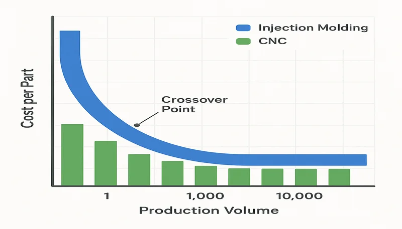
Ja, pick-and-place-overmolding is economisch haalbaar voor volumes vanaf 1,000–5,000 onderdelen. Deze methode gebruikt twee afzonderlijke enkelvoudige matrijzen — één voor het substraat en één voor de overmold — met handmatige of gerobotiseerde overdracht ertussen. De totale matrijskosten bedragen $80K–$200K, aanzienlijk minder dan voor een roterende tweekomponentenmatrijs. Voor prototypeaantallen onder 500 onderdelen kunnen 3D-geprinte substraten met zachte matrijzen (aluminium matrijzen) worden overmold tegen matrijskosten van $5K–$15K, hoewel de hechtsterkte door het poreuze oppervlak van geprinte substraten lager kan zijn. Siliconenovermolding met vacuümgieten is een andere optie voor kleine volumes en kost $500–$3,000 per ontwerpiteratie.
thermoplastisch elastomeer: Een thermoplastisch elastomeer (TPE) is een klasse copolymeren die de rubberachtige flexibiliteit van elastomeren combineert met de smeltverwerkbaarheid van thermoplasten en doorgaans een Shore A-hardheid van 20 tot 90 heeft. ↩
insert molding: Insert molding is een spuitgietproces waarbij een voorgevormd onderdeel—doorgaans van metaal—in de matrijsholte wordt geplaatst voordat er kunststof omheen wordt geïnjecteerd, zodat één geïntegreerd onderdeel ontstaat. ↩
matrijsvulkanalyse: Matrijsvulkanalyse is een computersimulatietechniek die voorspelt hoe gesmolten polymeer een matrijsholte vult, wordt nagedrukt en afkoelt, uitgedrukt in vultijd (seconden), drukverdeling (MPa) en locatie van laslijnen. ↩
ontwerp van spuitgietmatrijzen: Het ontwerpen van spuitgietmatrijzen is een technische discipline waarbij gereedschap met geoptimaliseerde aanspuitposities, deellijnen, koelkanalen en uitwerpsystemen wordt ontwikkeld om maatvaste kunststof onderdelen te produceren. ↩
DFM: DFM (Design for Manufacturability) is een systematische technische aanpak waarbij onderdeelgeometrie, toleranties en materiaalkeuze worden getoetst aan de beperkingen van het productieproces om kosten en het risico op defecten te minimaliseren. ↩