 Overslaan naar inhoud

Als je sourcing spuitgietonderdelen en het evalueren van matrijsopties, de koudlopersysteem1 is een van de eerste beslissingen waar je voor komt te staan. Het is de eenvoudigere, goedkopere en meer gebruikte runnerconfiguratie — maar dat betekent niet dat het altijd de juiste keuze is. Begrijpen wanneer een koude runner zinvol is, hoe je er een goed ontwerpt en welke materialen er het beste doorheen lopen, kan je duizenden dollars per matrijs en weken debugtijd besparen. In deze gids behandelen we alles wat een ingenieur of inkoopmanager moet weten over koude runnersystemen — van basisprincipes tot praktische ontwerptips gebaseerd op twee decennia matrijsbouwervaring.
- Koude lopers zijn ongeverwade kanalen die gesmolten plastic naar matrijs holtes voeden.
- Tweeplaat- en drieplaatmatrijzen zijn de belangrijkste koude loopconfiguraties.
- Koude lopers zijn ideaal voor korte runs, grote onderdelen en thermisch gevoelige materialen.
- Loopvolumeverspilling van 15–30% is typisch maar recyclebaar met thermoplasten.
- Ontwerpbalancering en poortplaatsing zijn de twee meest kritieke variabelen.
Wat is een Koude Runner Systeem bij Spuitgieten?
Een koud loopsysteem in spuitgieten wordt gedefinieerd door de functie, beperkingen en afwegingen die in deze sectie worden uitgelegd. Een koud loopsysteem is het netwerk van ongeverwade kanalen in een spuitgietmatrijs dat gesmolten plastic van de machinespuitmond naar de holtepoorten brengt, en bij elke cyclus stolt.
In de praktijk is de koude loop de standaardconfiguratie voor de meeste spuitgietmatrijzen wereldwijd. Het is mechanisch eenvoudig, vereist geen temperatuurregelaars of verwarmde componenten, en werkt betrouwbaar voor een breed scala aan thermoplasten. De afweging is materiaalverspilling: de gestolde loop moet van het onderdeel worden gescheiden en ofwel worden weggegooid of worden vermalen en opnieuw verwerkt. Voor hoogvolume commodity-onderdelen waar de harskosten laag zijn, is deze verspilling vaak economisch acceptabel. Voor technische harsen of medische toepassingen waar regrind2 beperkt is, verschuift de economie naar hete lopers.
Hoe werkt een koud loopsysteem?
Het werkingsprincipe is eenvoudig. Tijdens de injectiefase duwt de machineschroef gesmolten plastic door de spuitmond in de matrijs tuitbus. Vanuit de tuit stroomt het smeltmateriaal door een primair loopkanaal dat vertakt in secundaire lopers, elk eindigend bij een poort die naar een holte leidt. Omdat de matrijs op een temperatuur ver onder het smeltpunt van het polymeer wordt gehouden (typisch 20–80 °C afhankelijk van het materiaal), begint het plastic in de loop af te koelen op het moment dat het de stalen wanden raakt.
Na het onderdeel gevuld en voldoende afgekoeld is, gaat de matrijs open en duwt het ejectiesysteem zowel het voltooide onderdeel als het uitgeharde spuitkanaal uit de matrijs. In een tweeplaatsmatrijs wordt het spuitkanaal aan dezelfde kant uitgestoten als het onderdeel. In een drieplaatsmatrijs wordt het spuitkanaal apart verwijderd, waardoor automatische separatie zonder handmatige interventie mogelijk is. De cyclus wordt vervolgens herhaald.
De belangrijkste variabelen die de prestaties van de koude loop beheersen zijn: loopdiameter (typisch 3–12 mm afhankelijk van onderdeelgrootte en materiaalviscositeit), looplengte (korter is altijd beter voor drukval), poorttype en -grootte (randpoorten, onderwaterpoorten en penpoorten zijn het meest gebruikelijk), en het aantal holtes in de opstelling. Een goed ontworpen koude loop levert een uniforme vulling aan elke holte met minimaal drukverlies en acceptabel afvalvolume.
Wat zijn de soorten koude spuitkanaalmatrijzen?
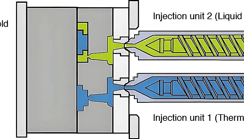
Er zijn twee primaire koude loopconfiguraties: tweeplaatsmatrijzen en drieplaatmatrijzen. Een derde variant, de geïsoleerde loopmatrijs, bestaat maar is zeldzaam in moderne productie.
Tweeplaat Koude Loopmatrijs
De tweepaatmatrijs is de eenvoudigste en meest economische configuratie. Hij heeft een enkele scheidingslijn: de matrijs splitst in twee helften – de holtekant (A-kant) en de kernkant (B-kant). De loop is uitgewerkt in een of beide helften van de scheidingslijn. Wanneer de matrijs opent, vallen zowel het onderdeel als de gestolde loop van dezelfde kant. Dit ontwerp is ideaal voor onderdelen met poorten op één zijde, en werkt goed voor laag- tot middenvolume productie waar handmatig ontgaten acceptabel is of waar robot pickers de loop automatisch kunnen scheiden.
Drieplaat Koude Loopmatrijs
De drieplaatsmatrijs voegt een tweede scheidingslijn toe, waardoor drie platen ontstaan: de stripperplaat, de A-plaat en de B-plaat. De runner bevindt zich op de eerste scheidingslijn (tussen de stripperplaat en de A-plaat), terwijl het onderdeel wordt gevormd op de tweede scheidingslijn (tussen de A-plaat en B-plaat). Tijdens het uitwerpen opent de matrijs achtereenvolgens bij beide scheidingslijnen, waardoor de runner automatisch van de onderdelen wordt gescheiden. Dit maakt gating op elk oppervlak van het onderdeel mogelijk (niet alleen de rand) en zorgt voor automatisch ontgaten — een belangrijk voordeel in omgevingen met grote volumes of geautomatiseerde productie.
De afweging is complexiteit: drieplaatsmatrijzen zijn duurder om te bouwen en te onderhouden, hebben hogere matrijshoogtes (vereisen grotere persen), en hebben extra beweegbare componenten die slijtage vergroten. In onze ervaring zijn drieplaatsmatrijzen gerechtvaardigd wanneer de onderdeel geometrie centraal invoeren vereist, wanneer productievolumes meer dan 100,000 cycli overschrijden, of wanneer arbeidskosten voor handmatig ontgieten te hoog worden.
“Cold runner molds are the most widely used mold configuration worldwide for injection molding.”Echt
Dit is correct. Koude runner matrijzen vormen de meerderheid van de wereldwijd gebruikte spuitgietmatrijzen. Hun eenvoud, lagere gereedschapskosten en brede materiaalcompatibiliteit maken ze de standaardkeuze voor de meeste toepassingen.
“In a three-plate mold, the runner and part eject from the same parting line simultaneously.”Vals
In een drieplaatsmatrijs wordt de runner gescheiden op een aparte scheidingslijn van het onderdeel, wat automatische scheiding mogelijk maakt. Dit is het belangrijkste voordeel ten opzichte van tweeplaatsmatrijzen waar beide van dezelfde scheidingslijn vallen.
Wanneer moet u een koude loop kiezen boven een hete loop?
Dit is de vraag die we het vaakst horen van klanten die matrijsopties evalueren. Het antwoord hangt af van vier factoren: productievolume, materiaalkosten, onderdeelgeometrie en kleurveranderingsfrequentie.
Koude runners zijn de betere keuze wanneer: (1) Het productievolume laag tot gemiddeld is (onder 500.000 onderdelen) — het lagere spuitgietvorm kosten van een koude runner matrijs zorgen voor een sneller ROI. (2) Materiaalkosten zijn laag — als je PP, PE of PS spuitgiet voor een paar dollar per kilogram, is de runnerafvalboete minimaal. (3) Kleurveranderingen zijn frequent — koude runners spoelen direct door omdat er geen verwarmde verdeelblokken zijn om door te spoelen. (4) Je hebt meercavitair productie met eenvoudige onderdeelgeometrieën nodig.
Hete runners worden aantrekkelijker bij grote volumes (meer dan 1 miljoen onderdelen), met dure technische kunststoffen waar het elimineren van runnerafval aanzienlijke materiaalkosten bespaart, of wanneer cyclusoptimalisatie cruciaal is — hete runners kunnen cyclus tijden verkorten door de tijd die nodig is om de runner te koelen en uit te werpen te elimineren.
| Factor | Cold Runner | Hete hardloper |
|---|---|---|
| Tooling cost | $5.000–$15.000 lager | $15.000–$50.000 hoger |
| Spuitkanaalafval | 15–30% per shot | Near zero |
| Kleurverandering | Snel (3–5 shots) | Langzaam (10–30 schoten) |
| Onderhoud | Laag | Hoger (verwarmers, thermokoppels) |
| Cyclustijd | Langer (runnerkoeling) | Korter |
| Best for | Low-mid volume, frequent color changes | Hoog volume, dure kunststoffen |
Welke materialen werken het beste met koude loopsystemen?
De meeste thermoplasten werken goed met koude spuitkanalen, maar sommige materialen zijn beter geschikt dan andere. De belangrijkste materiaal eigenschappen die de werking van koude spuitkanalen beïnvloeden zijn smeltviscositeit, thermische stabiliteit en krimpgedrag.
Polypropyleen (PP) en polyethyleen (PE) zijn de meest voorkomende koude runner materialen qua volume. Hun lage kosten, lage viscositeit en brede verwerkingsvenster maken ze ideaal geschikt voor ongeverwarmde kanaalsystemen. PP koude runners worden overal in aangetroffen, van verpakkingsdoppen tot autobatterijbehuizingen.
Nylon (PA6, PA66) werkt goed in koude spuitkanalen maar vereist aandacht voor het vochtgehalte. Nylon is hygroscopisch — het absorbeert vocht uit de lucht — en moet grondig gedroogd worden voor het spuitgieten om spatten en zwakke laslijnen te voorkomen. In een koud spuitkanaal betekent het langere stromingspad, in vergelijking met hete spuitkanalen, dat het materiaal een voldoende temperatuur moet behouden om vroegtijdige bevriezing te voorkomen. Voor glasgevuld nylon (PA6-GF30, PA66-GF30) moeten de diameters van de spuitkanalen 20-30% worden vergroot om de hogere viscositeit te accommoderen.
Engineering Resins and Specialty Materials
Polycarbonate (PC) and acrylic (PMMA) are also well-suited to cold runners. These materials have higher melt temperatures (280-320 °C for PC) but good thermal stability, which means they flow well through unheated channels without premature solidification. PC in particular benefits from cold runner simplicity in optical lens and electronic housing applications, where material purity and surface finish consistency are essential. Acrylic (PMMA) cold runner molds are common in automotive lighting and display applications.
Materials that are challenging in cold runners include PVC (thermal degradation risk if the runner is too long), PEEK (very high melt temperature makes cold runners impractical for most applications), and liquid silicone rubber (LSR), which always requires a cold runner but of a completely different design. If you are working with specialty resins, talk to your spuitgieten partner early in the design process to evaluate runner system feasibility and cost impact.
How Do You Design an Optimal Cold Runner System?
Good cold runner design is not complicated, but it demands attention to a few critical parameters. Get any of these wrong, and you will spend weeks debugging short shots, sink marks, or unbalanced fills.
Runner Diameter and Shape
The standard recommendation is a full-round runner cross-section, which provides the best surface-area-to-volume ratio for heat retention and low pressure drop. The runner diameter should be approximately 1.5× the maximum wall thickness of the part, with a practical range of 3–12 mm. Too small, and you get excessive pressure drop and premature freeze-off. Too large, and you waste material and extend cycle time. A trapezoidal runner is an acceptable alternative when both halves of the mold cannot be machined, but it increases pressure drop by 15–25% compared to a full-round design.
Runner Layout and Balancing
For multi-cavity molds, the runner layout must be balanced so that every cavity fills at the same time and pressure. An artificially balanced layout uses different runner diameters and lengths to equalize flow resistance. A naturally balanced layout arranges cavities symmetrically so that the flow path to each cavity is identical — these are always preferred because they are more robust to viscosity changes and process variations. In our mold shop, we use Moldflow simulation3 to verify fill balance before cutting steel, reducing first-shot debugging time by approximately 40%. With in-house mold manufacturing producing over 100 sets per month, we handle complex runner balancing across diverse part geometries.
Poortontwerp
The gate is the narrowest point in the flow path and has the greatest impact on part appearance and dimensional accuracy. Common gate types for cold runners include: edge gates (simplest, used on the parting line), submarine gates (tunnel gates that are automatically sheared during ejection), and pin gates (small-diameter gates fed through a three-plate mold). Gate size should be approximately 50–80% of the part wall thickness at the gate location. Too small a gate causes high shear, which can degrade the material and create visible gate marks. Too large a gate extends packing time and makes degating difficult.
What Are Common Cold Runner Defects and How to Fix Them?
Common cold runner defects and how to fix them are the main categories or options explained in this section. Even with good design, cold runner molds can produce defects. Here are the most common issues we encounter and their solutions.
Short shots occur when the cavity does not fill completely. In cold runner molds, the most common cause is a runner that is too small or too long, creating excessive pressure drop. The fix is to increase runner diameter or reduce runner length by repositioning the cavities closer to the sprue. Increasing injection pressure or speed can also help, but this is a band-aid — the underlying geometry should be corrected.
Flow lines and weld lines appear where multiple flow fronts meet. In cold runner molds, these often occur at runner junctions or where two gates feed the same cavity. Solutions include: relocating gates to move weld lines to non-critical areas, increasing melt temperature to improve flow fusion, or using a single gate design for cosmetically critical parts.
“Regrind from cold runner waste can be blended with virgin material at 15–20% ratios for most non-critical thermoplastic applications.”Echt
Yes, this is standard industry practice. For commodity thermoplastics like PP and PE, regrind at 15–20% blend ratios maintains mechanical properties while significantly reducing effective material waste cost.
“Hot runner systems always produce higher quality parts than cold runner systems regardless of production volume.”Vals
Quality depends on proper mold design, not runner type. Cold runners produce equally high-quality parts when well-designed. The choice depends on volume, material cost, and color change needs.
Excessive runner waste is not a defect per se, but it is a common cost concern. If runner waste exceeds 30% of the total shot weight, consider: reducing runner diameter (within pressure constraints), switching to a hot runner for the primary manifold while keeping cold runners for the final drops (a hybrid system), or implementing a regrind program to recycle the runner material. For most thermoplastics, regrind at 15–20% blend ratios is acceptable for non-critical applications.
At ZetarMold, we have been building injection molds since 2005 — over 20 years of experience with both cold runner and hot runner systems. Our Shanghai facility operates 47 injection molding machines ranging from 90T to 1850T, giving us the flexibility to run cold runner molds for everything from small precision parts to large structural components. With our in-house mold manufacturing capability and experience across 400+ materials, we can help you determine the optimal runner system for your specific application.
What Are the Most Frequently Asked Questions About Cold Runner Systems?
What is the typical runner waste percentage in a cold runner mold?
Runner waste in a cold runner mold typically ranges from 15% to 30% of the total shot weight, depending on the number of cavities, runner layout, and part size. For small, multi-cavity molds, the runner volume can actually exceed the part volume, pushing waste above 30%. For larger single-cavity parts, waste may drop to 10–15%. The good news is that for most thermoplastics, this runner material can be reground and reprocessed at blend ratios of 15–20% with virgin resin, significantly reducing effective material loss.
Can cold runner waste material be recycled?
Yes, cold runner waste can be recycled for most thermoplastic materials. The solidified runners are ground into regrind using granulators and then blended back with virgin material at typical ratios of 15–20%. This regrind process works well for commodity materials like polypropylene and polyethylene, where the cost savings are meaningful. However, for medical-grade parts, optical components, or applications with strict regulatory requirements, regrind use may be prohibited or limited. Always verify material integrity after multiple regrind cycles, as thermal degradation can reduce mechanical properties.
How do you size a cold runner channel?
A cold runner channel should be sized at approximately 1.5 times the maximum wall thickness of the molded part, with a practical diameter range of 3 to 12 millimeters. Full-round cross-sections are preferred because they offer the best surface-area-to-volume ratio for heat retention and low pressure drop. If the runner is too small, excessive pressure drop causes short shots and premature freeze-off. If the runner is too large, material waste increases and cycle times extend due to longer cooling requirements.
What is the difference between a two-plate and three-plate cold runner mold?
A two-plate mold has a single parting line where both the part and runner eject together, making it simpler and cheaper to build. A three-plate mold adds a second parting line that allows the runner to separate from the part automatically during ejection. Three-plate molds enable gating on any surface of the part, not just the parting line edge, which is essential for center-gated or multi-gated geometries. The trade-off is higher tooling cost, increased mold height, and more maintenance due to additional moving components.
When is a cold runner not recommended?
Cold runners are not recommended when molding very high-cost engineering resins where 15–30% material waste becomes economically prohibitive, when production volumes exceed one million cycles and cycle time optimization is critical, or when working with liquid silicone rubber that requires specialized cold runner designs with actively cooled channels. They are also less suitable for applications requiring absolutely zero post-molding operations, since the solidified runner must always be separated from the finished part. For medical-grade parts where regrind is restricted, hot runners eliminate waste entirely.
How does runner length affect injection pressure?
Runner length has a direct and significant impact on injection pressure requirements. Pressure drop through a cold runner is proportional to the runner length and inversely proportional to the fourth power of the runner diameter. Doubling the runner length roughly doubles the pressure drop, while doubling the diameter reduces pressure drop by a factor of sixteen. This is why mold designers always strive to minimize runner length by positioning cavities as close to the sprue as possible and using naturally balanced layouts.
Can you use cold runners for multi-material molding?
Cold runners can be used for multi-material molding in certain configurations, but they are more limited than hot runner systems. Two-shot or overmolding applications can use cold runners in the stationary mold half while the rotating core moves between stations. However, cold runners cannot selectively control material flow to different cavities the way valve-gated hot runner systems can. For complex multi-material applications with three or more materials, or where precise material placement is required, hot runner systems are generally more appropriate.
What gate types work best with cold runner systems?
The most common and effective gate types for cold runner systems are edge gates, submarine (tunnel) gates, and pin gates. Edge gates are the simplest and most economical, machined directly on the parting line. Submarine gates are automatically sheared during ejection, making them ideal for automated production where manual degating is undesirable. Pin gates, used in three-plate molds, provide small-diameter gate vestige and allow gating on any surface. Gate size should be 50–80% of the part wall thickness at the gate location to balance fill quality and degating ease.
-
cold runner system: cold runner system refers to an unheated channel system in an injection mold that conveys molten plastic from the machine nozzle to the cavity gates, solidifying with each cycle. ↩
-
regrind: regrind refers to the process of grinding solidified runners and rejected parts into reusable plastic granules, typically blended with virgin material at 15-20% ratios. ↩
-
Moldflow simulation: Moldflow simulation refers to computer-aided engineering software that simulates plastic flow, cooling, and warpage in injection molds to optimize design before manufacturing. ↩



 EN
EN  ES
ES  FR
FR  DE
DE  PT
PT  AR
AR  RU
RU  JA
JA  KO
KO  IT
IT  NL
NL  TR
TR  PL
PL 