 콘텐츠로 건너뛰기

리브 설계는 사출 성형에서 단순한 형상 규칙이 아닙니다; 재료 거동 문제입니다. ABS, PC, PP, 나일론, POM 및 유리 충전 수지는 각각 다르게 수축, 냉각 및 응력에 저항하므로, 한 폴리머에서 작동하는 동일한 리브가 다른 폴리머에서는 싱크 마크, 뒤틀림 또는 이젝션 손상을 일으킬 수 있습니다. 그래서 리브 두께, 높이, 루트 반경, 드래프트 및 게이트 위치는 몰드 강재가 절단, 샘플링, 테스트 및 적절히 검증되기 전에 수지 계열에 대해 확인되어야 합니다.
구매자와 엔지니어에게 실질적인 목표는 간단합니다: 벽 교차부에 두꺼운 질량을 생성하지 않으면서 리브를 사용하여 강성을 추가하는 것입니다. 우리의 금형 DFM 검토에서는 먼저 수지가 비결정성, 반결정성, 탄성중합체, 또는 충전재인지 식별한 후, 해당 거동에 맞춰 리브-벽 비율과 냉각 전략을 조정합니다. 이 글은 재료 특성이 리브 설계 결정을 어떻게 변경하는지와 가장 일반적인 공구 및 성형 결함을 피하는 방법을 설명합니다.
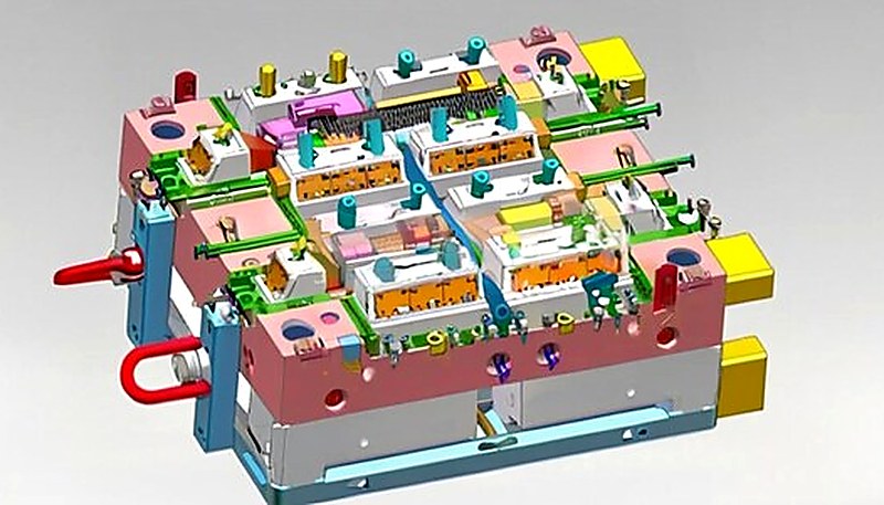
- 리브 두께는 폴리머 종류에 따라 명목 벽 두께의 40-75%가 되어야 함
- 반결정성 재료는 더 높은 수축률로 인해 더 얇은 리브가 필요합니다
- 유리 충전 폴리머는 더 두꺼운 리브를 허용하지만 이방성 수축 문제를 만듦
- 싱크 마크 심각도는 교차부 질량과 재료 냉각 거동에 따라 달라집니다
- 깨끗한 리브 이젝션을 위해 측면당 0.5-1.5도의 드래프트 각도가 필수적임
What Are the Material Constraints for Rib Geometry?
리브 형상에 대한 재료 제약은 수지 수축률, 냉각 프로파일, 강성 목표, 이젝션 마찰, 외관 싱크 위험입니다.
In 사출 성형, 리브는 균일하게 두꺼운 벽의 무게와 사이클 시간 증가 없이 강성을 높이기 위해 명목 벽에서 수직으로 돌출된 얇은 보강 구조입니다. 근본적인 과제: 모든 리브는 벽과 만나는 지점에서 국부적인 질량 집적을 생성하며, 이 추가 질량은 수축 관련 외관 결함을 유발합니다.
리브-벽 교차점의 용융 폴리머가 냉각될 때, 두꺼운 단면은 주변 표피보다 더 오래 액체 상태로 남습니다. 코어가 마침내 고화되고 수축하면 이미 얼어붙은 외부 표면을 안쪽으로 당깁니다 — 보이는 싱크 마크 리브 반대편의 Class A 표면에. 이 결함의 심각성은 일정하지 않습니다; 거의 전적으로 재료의 내부 구조와 수축 거동에 달려 있습니다.
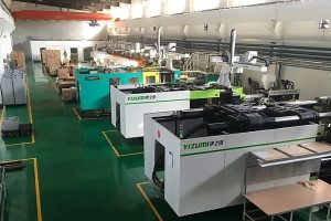
우리 상하이 공장에서는 90톤에서 1850톤까지 47대의 사출 성형기를 운영하며, 400가지 이상의 다양한 플라스틱 재료를 가공해 왔습니다. 이러한 광범위한 경험은 ABS용으로 설계된 리브가 PP에서 두께 비율이 조정되지 않으면 치명적으로 실패할 수 있다는 것을 직접 목격했음을 의미합니다 — 동일한 명칭 형상이 한 재료에서는 거의 보이지 않는 싱크 마크를, 다른 재료에서는 깊은 홈을 생성할 수 있습니다.
비정질 폴리머 (ABS, PC, PMMA)는 낮고 거등방성에 가까운 수축률(일반적으로 0.2-0.8%)을 보입니다. 무작위 분자 배열은 상대적으로 균일하게 수축함을 의미합니다. 이는 설계자에게 약간의 여유를 줍니다 — 리브는 심각한 싱크 마크 없이 벽 두께의 50-70%가 될 수 있습니다.
반결정성 폴리머 (PP, PE, PA6, PA66)는 다른 이야기입니다. 냉각되면서 분자가 더 조밀하게 배열된 규칙적인 결정 구조로 접혀 훨씬 더 높은 수축률을 생성합니다 — 종종 1.0-3.0%입니다. 이는 더 얇은 리브(벽 두께의 40-50%)와 유도된 흐름 방향성을 제어하기 위한 더 신중한 게이팅을 요구합니다.
“리브는 전체 벽 두께를 증가시키는 것에 비해 최소한의 무게 추가로 부품 강성을 크게 증가시킵니다.”True
리브는 균일하게 두꺼운 벽의 재료 비용, 냉각 시간 손실 및 싱크 위험 없이 표적 보강을 제공하여 단면 2차 모멘트를 증가시킵니다.
“구조적 강성을 극대화하기 위해 명칭 벽과 동일한 두께로 리브를 안전하게 설계할 수 있습니다.”False
벽 두께와 동일한 리브는 교차점에서 대규모 열점을 생성하여, 외관 표면에 싱크 마크를 보장하고 내부 공극을 생성할 가능성이 있습니다.
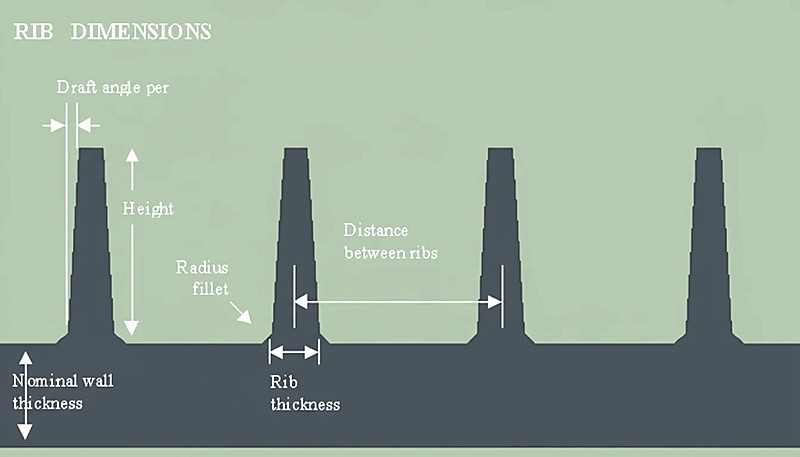
재료 계열별 수축률은 어떻게 다른가요?
재료 수축과 리브 형상 간의 관계는 선형이 아닙니다 — 시스템 수준의 제약 조건입니다. 확립된 DFM guidelines1 및 국제 수축 기준2, 아래 표는 폴리머 계열별 권장 설계 매개변수를 제공합니다. 이 값들은 시작점을 나타냅니다; 항상 다음을 통해 확인하세요 Moldflow simulation3 특정 부품 형상 및 게이트 위치에 대해.
| 매개변수 | 비정질 (PC, ABS) | 반결정성 (PP, PA6) | 유리 충전 (PA66-GF30) |
|---|---|---|---|
| 리브/벽 비율 | 50-70% | 40-50% | 55-75% |
| 수축률 | 0.2-0.8% | 1.0-3.0% | 0.2-0.8% (이방성) |
| 구배 각도 | 측면당 0.5-1.0 | 측면당 0.5-1.5 | 1.0-2.0 측면당 |
| 기본 반경 | 0.25 × t(벽) | 0.20 × t(벽) | 0.25 × t(벽) |
| 최대 리브 높이 | 3 × t(벽) | 2.5 × t(벽) | 3 × t(벽) |
| 싱크 위험 | Low-Medium | 높음 | 낮음 (하지만 뒤틀림 위험 있음) |
유리 충전 열을 주목하세요: 유리 섬유는 흐름 방향의 체적 수축을 극적으로 감소시키지만, 횡방향 수축에는 거의 영향을 미치지 않습니다. 이 이방성 거동은 부품이 싱크되지 않을 수 있지만, 리브 배치가 방향성 수축을 고려하지 않으면 상당히 뒤틀릴 수 있음을 의미합니다. 실제로, 우리는 항상 공구 강철을 확정하기 전에 유리 충전 재료에 대해 충전 + 압축 + 뒤틀림 시뮬레이션을 실행합니다.
왜 비정질과 결정성 폴리머는 서로 다른 리브 전략이 필요한가요?
비결정성 및 결정성 폴리머는 서로 다른 리브 전략으로 처리됩니다. 왜냐하면 그들은 다르게 응고, 수축, 압축 압력을 유지하기 때문입니다. 비결정성 재료는 액체에서 고체로 점진적으로 전환되므로 급격한 상 변화가 없습니다. 이 점진적인 응고는 리브-벽 접합부가 압력을 균등화할 시간이 더 많아져 차등 수축이 적게 발생함을 의미합니다. 보기 흉한 결과 없이 리브 두께를 벽의 70%에 더 가깝게 밀어붙일 수 있습니다.
반결정성 폴리머는 특정 온도에서 급격한 결정화 현상을 겪습니다. 결정화가 발생하면 재료가 공격적으로 수축합니다. 리브 베이스가 너무 두꺼우면 해당 국부 영역의 결정화 수축이 표면을 평평하게 유지하던 패킹 압력을 압도합니다. 결과: 게이트가 얼고 난 후 어떤 양의 패킹 압력으로도 고칠 수 없는 깊고 보이는 싱크 마크가 생깁니다.
With over 20 years of injection molding experience and an in-house mold manufacturing facility, we’ve learned to adjust rib proportions before cutting steel. A common mistake we catch in DFM reviews: designers applying PC rib ratios to a PP part. The part looks fine in CAD — but the first shot shows deep sink lines on every rib location.
“Increasing packing pressure alone cannot eliminate sink marks caused by oversized ribs in high-shrinkage crystalline materials.”True
Once the gate freezes off, no additional pressure reaches the thick section. The only effective fix is reducing the rib-wall thickness ratio to match the material’s shrinkage characteristics.
“Glass-filled materials always produce better rib outcomes because their overall shrinkage is lower.”False
While glass fibers reduce overall shrinkage, they create strong anisotropic effects. Ribs may not sink, but differential shrinkage between flow and transverse directions can cause significant warpage.
각 재료에 대한 실용적인 설계 규칙은 무엇인가?
Theory is useful, but on the shop floor, designers need actionable rules. Here’s what we apply in our DFM reviews based on the specific polymer a customer selects:
For ABS and PC (amorphous): Rib thickness = 50-70% of nominal wall. Minimum draft = 0.5 per side. Base radius = 0.25 × wall thickness. These materials are forgiving — you can push toward 70% if the opposite surface is non-cosmetic.
For PP and HDPE (semi-crystalline, unfilled): Rib thickness = 40-50% of wall. Minimum draft = 1.0 per side. Base radius = 0.20 × wall (smaller radius to minimize mass accumulation). These materials will show sink if you exceed 50% — there is no magic processing trick to fix an oversized rib in PP.
For PA66-GF30 (glass-filled): Rib thickness = 55-75% of wall. Draft = 1.0-2.0 per side (glass fibers increase ejection friction). The reduced shrinkage allows thicker ribs, but you must gate to minimize flow-length variation across ribs, or warpage will be your problem instead of sink.
For 사출 금형 designs using PC/ABS blends: Treat these as amorphous — the PC component dominates the shrinkage behavior. Rib ratios of 55-65% of wall thickness are the sweet spot. These blends are common in consumer electronics housings where both strength and surface quality matter.
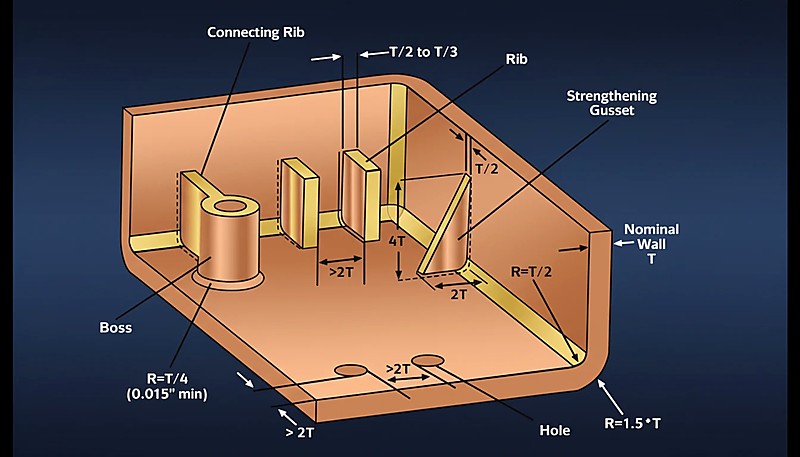
리브 설계 프로세스를 단계별로 어떻게 실행해야 하는가?
The rib design process is a controlled DFM sequence: define loads, lock resin data, size ribs, check spacing, simulate, then review with the molder. Here is the workflow we follow for every new part with structural ribs:
Step 1 — Define structural requirements: Determine the stiffness targets and load cases. Calculate the required moment of inertia, then work backward to estimate rib height and spacing rather than guessing.
Step 2 — Select material and lock shrinkage data: Get the actual shrinkage values from the material datasheet for your specific grade and wall thickness. Don’t use generic values — PA66-GF30 from different suppliers can vary by 0.2-0.4% in shrinkage.
Step 3 — Calculate rib proportions: Apply the material-specific rib/wall ratio from the table above. If the wall is 2.5mm and you’re using PP, the rib base should be 1.0-1.25mm (40-50%). Set draft at 1.0 per side and base radius at 0.5mm.
Step 4 — Check rib spacing: Maintain at least 2× (preferably 3×) the wall thickness between adjacent ribs. Tighter spacing causes thin-wall filling problems and amplifies differential cooling.
Step 5 — Run Moldflow simulation: Simulate fill, pack, and warp. Look specifically at volumetric shrinkage at the rib-wall intersection and deflection results. This is where you catch problems before spending five figures on tooling.
Step 6 — DFM review with your molder: Share the simulation results with your injection molding partner. A good molder will challenge the rib layout based on their process window — packing pressure capability, cooling channel access, and ejection strategy all affect whether a rib design works in practice.
실제 응용 사례에서 재료별 리브 설계는 어떻게 보여지나요?
Real-world rib applications are useful because each material family exposes a different failure mode: sink, warp, ejection drag, or cooling imbalance. Automotive interior brackets (PP + Talc): We regularly produce dashboard support brackets in talc-filled PP. The talc reduces shrinkage slightly compared to unfilled PP, but the crystalline nature still demands ribs at 40-45% of wall thickness. A typical 2.0mm wall gets 0.8-0.9mm ribs with 1.0 draft per side.
Laptop housings (PC/ABS): Consumer electronics demand Class A surfaces with zero visible sink. The amorphous PC/ABS blend allows ribs at 60% of the 2.2mm wall (about 1.3mm base), and we use localized thin-wall sections behind cosmetic areas to further reduce sink visibility.
Industrial enclosures (PA66-GF30): Glass-filled nylon enclosures carry high structural loads. The ribs can be 65-70% of wall thickness thanks to low shrinkage, but warpage is the real enemy. We use balanced gate placement and fiber-orientation simulation to keep flat surfaces flat.
Material handling crates (HDPE): Deep-draw crates in HDPE use aggressive rib networks. The high shrinkage of HDPE (2.0-3.0%) means ribs must be thin — typically 40% of wall — but the non-cosmetic nature of these parts means moderate sink is acceptable, allowing designers to push the ratio slightly higher.
자주 묻는 질문
What is the maximum rib height allowed in injection molding?
Complete elimination of sink marks is extremely difficult for semi-crystalline materials when ribs exceed 45 percent of wall thickness. For amorphous polymers like PC and ABS, keeping ribs at or below 50 percent of wall thickness typically produces no visible sink on the cosmetic surface. Processing adjustments such as higher packing pressure, extended hold time, and increased cooling can reduce sink severity, but they cannot overcome a fundamentally oversized rib geometry. The most effective and reliable approach is to design the rib thickness correctly from the start based on the specific material family being used.
Can you eliminate sink marks on ribs completely?
Glass-filled materials allow thicker ribs at 55 to 75 percent of wall thickness due to the dramatically reduced volumetric shrinkage that glass fibers provide. However, they introduce significant anisotropic warpage risks because fibers orient in the flow direction and reduce shrinkage along that axis while doing little in the transverse direction. Unfilled semi-crystalline materials require thinner ribs at 40 to 50 percent to avoid sink marks, but their warpage behavior is more predictable. For glass-filled parts, always gate to minimize flow-length variation across the rib network, and run a dedicated warp simulation before committing to expensive tooling modifications.
How does rib design differ for glass-filled versus unfilled materials?
The base radius in rib design serves two critical and complementary functions. First, it reduces stress concentration at the sharp rib-wall junction, which directly improves the structural performance and fatigue life of the finished part under repeated loading. Second, it controls the amount of mass accumulation at that intersection point. The standard recommendation is a radius of 0.20 to 0.25 times the nominal wall thickness. Going larger adds excessive material and increases the risk of sink marks, while going smaller creates a stress riser that can lead to premature crack initiation and part failure under mechanical load.
What role does the base radius play in rib design?
대부분의 실제 응용 분야에서 수직 리브는 최고의 강성 대 중량 비율을 제공하며 구조적 보강을 위한 기본 선택입니다. 그러나 각진 리브나 곡선 리브는 소비자 제품의 미적 통합을 위해, 또는 자동차 브래킷과 같은 복잡한 하중 지지 형상에서 자연스러운 응력 경로를 따르기 위해 때때로 사용됩니다. 방향에 관계없이 중요한 제약 조건은 동일하게 유지됩니다: 리브-벽 접합부의 단면 두께는 싱크 마크를 방지하고 부품이 외관 및 구조적 요구 사항을 모두 충족하도록 재료별 리브 대 벽 두께 비율을 준수해야 합니다.
리브는 항상 명목 벽에 수직이어야 하나요?
코어 제거와 리브 설계는 부품 무게와 구조적 성능을 최적화하기 위한 쌍을 이루는 전략으로 함께 작동합니다. 코어 제거는 부품의 두꺼운 불필요한 부분을 제거하고 더 얇은 벽으로 대체한 다음 전략적으로 배치된 리브 네트워크로 보강합니다. 이 조합은 원료 소비를 줄이고 냉각 시간을 크게 단축하며 전반적인 치수 안정성을 향상시킵니다. 핵심 원칙은 먼저 코어 제거된 벽 두께를 설정한 다음, 제거된 원래 두꺼운 단면이 아닌 새로운 더 얇은 벽 치수에 대한 비율로 모든 리브의 크기를 조정하는 것입니다.
코어 제거와 리브 설계는 어떻게 함께 작동하나요?
성형 부품 표면 및 그 근처의 유리 섬유는 이젝션 중에 연마된 금형 벽에 대해 극도로 높은 마찰을 생성합니다. 특히 리브 구조에서는 리브가 제한된 드래프트 릴리프를 가진 깊고 좁은 캐비티를 형성하기 때문에 이 마찰 문제가 증폭됩니다. 충분한 드래프트 각도(일반적으로 유리 충전 재료의 경우 측면당 1.0~2.0도, 비충전 등급의 경우 0.5~1.0도)가 없으면 리브가 이젝션 중에 긁히거나 구부러지거나 파손될 수 있습니다. 이는 부품의 외관과 구조를 손상시킬 뿐만 아니라 수천 번의 생산 주기를 거쳐 금형 표면을 열화시킬 수도 있습니다.
유리 섬유 강화 재료는 왜 리브에 더 큰 드래프트 각도가 필요한가요?
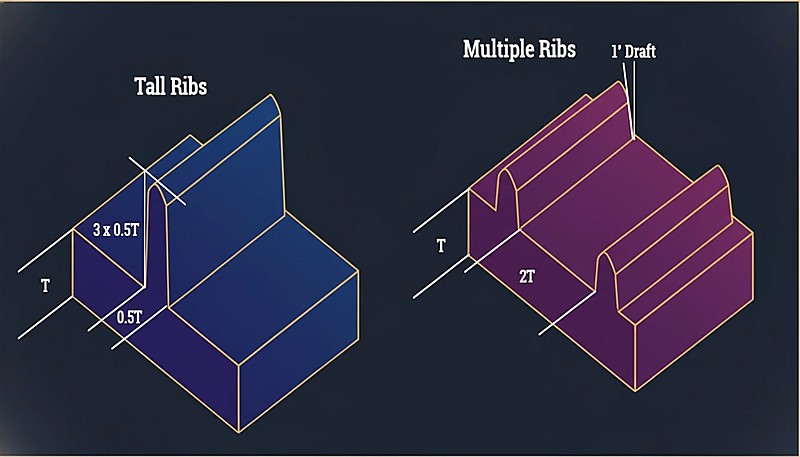
일반적인 엔지니어링 가이드라인으로, 리브 높이는 기준 벽 두께의 세 배를 초과하지 않아야 합니다. 더 높은 리브는 용융 플라스틱이 빠르게 냉각되어 공기를 가두거나 단쇼트를 일으킬 수 있는 좁고 깊은 채널로 흘러 들어가야 하기 때문에 충전 문제를 일으킵니다. 구조 분석에서 벽 높이의 세 배인 표준 리브가 제공할 수 있는 것보다 더 큰 강성이 필요한 경우, 더 나은 접근 방식은 적절한 간격을 두고 여러 개의 더 짧은 리브를 사용하는 것입니다. 이렇게 하면 보강이 더 균일하게 분배되고 사출 성형 공정 중 안정적인 충전이 유지됩니다.
리브 설계에 대한 전문 DFM 검토가 필요하신가요? ZetarMold의 엔지니어링 팀은 부품 형상을 분석하고, 재료별 리브 비율을 권장하며, 금형 투자 전 Moldflow 시뮬레이션을 실행할 수 있습니다. 400종 이상의 재료에 걸친 20년 이상의 경험으로, 우리는 설계 문제를 조기에 발견하여 시간과 금형 비용을 절약해 드립니다.
무료 견적 및 DFM 분석 요청하기 →



 EN
EN  ES
ES  FR
FR  DE
DE  PT
PT  AR
AR  RU
RU  JA
JA  KO
KO  IT
IT  NL
NL  TR
TR  PL
PL 