...

How Do Material Properties Influence Rib Design in Plastic Injection Molding?

• ZetarMold Engineering Guide
• Plastic Injection Mold Manufacturing Since 2005
• Built by ZetarMold engineers for buyers comparing mold and molding solutions.

リブ設計は射出成形における単なる幾何学的ルールではなく、材料挙動の問題です。ABS、PC、PP、ナイロン、POM、ガラス充填樹脂は、収縮、冷却、応力抵抗がそれぞれ異なるため、あるポリマーで機能する同じリブが、別の材料ではシンクマーク、反り、または取り出し損傷を引き起こす可能性があります。そのため、金型鋼材が切削、試作、テスト、適切に検証される前に、リブの厚さ、高さ、根元R、抜き勾配、ゲート位置を樹脂ファミリーに対して確認する必要があります。

バイヤーとエンジニアにとって、実用的な目標は単純です:壁の交差部に厚い塊を作らずにリブを使って剛性を追加することです。当社の金型DFMレビューでは、まず樹脂が非晶性、半結晶性、エラストマー、充填材のいずれであるかを特定し、その挙動に基づいてリブと壁の比率と冷却戦略を調整します。この記事では、材料特性がリブ設計の決定をどのように変え、最も一般的な金型・成形不良を回避する方法について説明します。
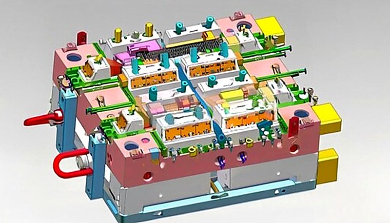
3D design of plastic injection mold
リブ配置を示す3D金型設計
要点
  • リブ厚は、ポリマー種類に応じて公称壁厚の40-75%でなければなりません
  • 結晶性材料は収縮率が高いため、より薄いリブが必要です
  • ガラス充填ポリマーはより厚いリブを可能にしますが、異方性収縮の課題を生み出します
  • 沈み跡の深刻度は、接合部の質量と材料の冷却挙動に依存します
  • リブの綺麗な取り出しには、0.5-1.5度/側面の抜き勾配が不可欠です

What Are the Material Constraints for Rib Geometry?

リブ形状に対する材料制約は、樹脂収縮率、冷却プロファイル、剛性目標、取り出し摩擦、および外観上のシンクリスクです。

射出成形、リブは、均一に厚い壁の重量やサイクルタイムのペナルティを追加せずに剛性を高めるために、名目上の壁から垂直に突き出た薄い補強要素です。根本的な課題は、すべてのリブが壁と接する部分で局所的な質量の蓄積を生み出し、その余分な質量が収縮に関連する外観上の欠陥を引き起こすことです。

リブと壁の交差部で溶融ポリマーが冷却されると、厚い断面は周囲の表皮よりも長く液体のままです。コアが最終的に固化して収縮すると、すでに凍結した外表面を内側に引き込み、目に見える シンクマーク リブの反対側のクラスA面上で。この欠陥の深刻度は一定ではなく、ほぼ完全に材料の内部構造とその収縮挙動に依存します。

🏭 ZetarMold Factory Insight
当社の上海工場では、90トンから1850トンまでの47台の射出成形機を稼働させ、400種類以上の異なるプラスチック材料を加工してきました。この幅広い経験により、ABS用に設計されたリブが、厚み比を調整しないとPPでは壊滅的に失敗する様子を直接目撃してきました。同じ公称形状でも、ある材料ではほとんど見えないシンクマークを生じ、別の材料では深い溝を生じることがあります。

非晶性ポリマー (ABS、PC、PMMA)は低く、ほぼ等方性の収縮を示します(通常0.2-0.8%)。分子のランダムな配列により、比較的均一に収縮します。これにより設計者は多少の余裕が得られ、深刻なシンクマークなしにリブを壁厚の50-70%とすることができます。

半結晶性ポリマー (PP, PE, PA6, PA66) は別の話です。冷却する際、分子が規則的な結晶構造に折り畳まれ、より密に詰まるため、はるかに高い収縮(しばしば 1.0-3.0%)を生じます。これにより、より薄いリブ(壁厚の40-50%)と、流動誘起配向を制御するためのより慎重なゲーティングが要求されます。

「リブは、壁厚全体を増やすのに比べ、最小限の重量増加で部品の剛性を大幅に向上させます。」

リブは断面二次モーメントを増加させ、均一に厚い壁に伴う材料コスト、冷却時間の増加、シンクマークのリスクなしに、ターゲットを絞った補強を提供します。

「構造強度を最大化するために、リブを名目上の壁と同じ厚さで安全に設計できます。」

壁と同じ厚さのリブは、接合部に大きな熱的ホットスポットを作り、外観面に沈み跡を確実に生じさせ、内部ボイドを生む可能性があります。
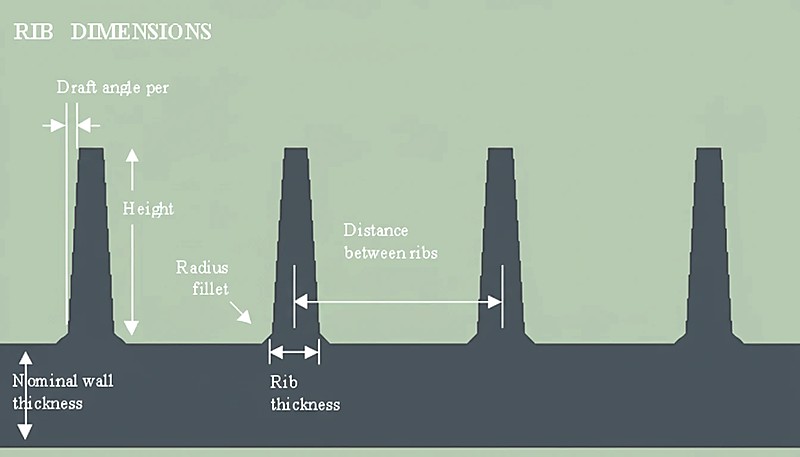
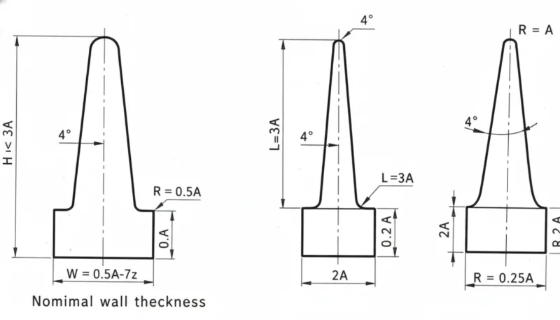
射出成形図におけるリブの寸法
材料別リブ寸法

材料ファミリーごとの収縮率はどのように異なりますか?

材料収縮とリブ形状の関係は線形ではありません — これはシステムレベルの制約です。確立された DFM guidelines1 および国際 収縮基準2、以下の表はポリマーファミリー別の推奨設計パラメータを示しています。これらの値は出発点であり、常に確認が必要です。 Moldflow simulation3 具体的な部品形状とゲート位置に応じて。

パラメータ 非晶性 (PC, ABS) 結晶性樹脂 (PP、PA6) ガラス充填 (PA66-GF30)
リブ/壁厚比 50-70% 40-50% 55-75%
収縮率 0.2-0.8% 1.0-3.0% 0.2-0.8% (異方性)
ドラフト角度 0.5-1.0度/側面 側面あたり 0.5-1.5 側面あたり 1.0-2.0
ベース半径 0.25 × t(壁厚) 0.20 × t(壁厚) 0.25 × t(壁厚)
最大リブ高さ 3 × t(壁厚) 2.5 × t(壁厚) 3 × t(壁厚)
シンクリスク Low-Medium 高い 低い(ただし反りリスクあり)

ガラス繊維充填の列に注目してください:ガラス繊維は流れ方向の体積収縮を劇的に減少させますが、横方向の収縮にはほとんど影響しません。この異方性の挙動は、部品が沈み込まない可能性がある一方で、リブの配置が方向性収縮を考慮していない場合、著しく反る可能性があることを意味します。実際には、ガラス繊維充填材料については、金型鋼材を決定する前に、常に充填+保圧+反りシミュレーションを実行します。

なぜ非晶性ポリマーと結晶性ポリマーでは異なるリブ戦略が必要なのですか?

非晶質ポリマーと結晶性ポリマーは、凍結、収縮、保圧の仕方が異なるため、異なるリブ戦略で扱われます。非晶質材料は液体から固体へ徐々に移行するため、鋭い相変化はありません。この徐々の凍結により、リブと壁の接合部は圧力を均等化する時間がより多くあり、収縮差が少なくなります。外観上の問題なく、リブの厚さを壁の70%に近づけることができます。

Semi-crystalline polymers undergo a sharp crystallization event at a specific temperature. When crystallization hits, the material contracts aggressively. If the rib base is too thick, the crystallization shrinkage in that localized zone overwhelms the packing pressure that was holding the surface flat. Result: a deep, visible sink mark that no amount of packing pressure can fix after the gate freezes.

🏭 ZetarMold Factory Insight
With over 20 years of injection molding experience and an in-house mold manufacturing facility, we’ve learned to adjust rib proportions before cutting steel. A common mistake we catch in DFM reviews: designers applying PC rib ratios to a PP part. The part looks fine in CAD — but the first shot shows deep sink lines on every rib location.

“Increasing packing pressure alone cannot eliminate sink marks caused by oversized ribs in high-shrinkage crystalline materials.”

Once the gate freezes off, no additional pressure reaches the thick section. The only effective fix is reducing the rib-wall thickness ratio to match the material’s shrinkage characteristics.

“Glass-filled materials always produce better rib outcomes because their overall shrinkage is lower.”

While glass fibers reduce overall shrinkage, they create strong anisotropic effects. Ribs may not sink, but differential shrinkage between flow and transverse directions can cause significant warpage.

各材料に対する実用的な設計ルールは何ですか?

Theory is useful, but on the shop floor, designers need actionable rules. Here’s what we apply in our DFM reviews based on the specific polymer a customer selects:

For ABS and PC (amorphous): Rib thickness = 50-70% of nominal wall. Minimum draft = 0.5 per side. Base radius = 0.25 × wall thickness. These materials are forgiving — you can push toward 70% if the opposite surface is non-cosmetic.

For PP and HDPE (semi-crystalline, unfilled): Rib thickness = 40-50% of wall. Minimum draft = 1.0 per side. Base radius = 0.20 × wall (smaller radius to minimize mass accumulation). These materials will show sink if you exceed 50% — there is no magic processing trick to fix an oversized rib in PP.

For PA66-GF30 (glass-filled): Rib thickness = 55-75% of wall. Draft = 1.0-2.0 per side (glass fibers increase ejection friction). The reduced shrinkage allows thicker ribs, but you must gate to minimize flow-length variation across ribs, or warpage will be your problem instead of sink.

について 射出成形金型 designs using PC/ABS blends: Treat these as amorphous — the PC component dominates the shrinkage behavior. Rib ratios of 55-65% of wall thickness are the sweet spot. These blends are common in consumer electronics housings where both strength and surface quality matter.

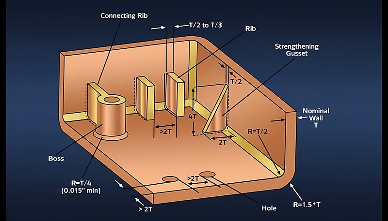
プラスチック射出成形部品のリブ、ボス、および壁の設計図
Rib boss wall diagram

リブ設計プロセスを段階的に実行するにはどうすればよいですか?

The rib design process is a controlled DFM sequence: define loads, lock resin data, size ribs, check spacing, simulate, then review with the molder. Here is the workflow we follow for every new part with structural ribs:

Step 1 — Define structural requirements: Determine the stiffness targets and load cases. Calculate the required moment of inertia, then work backward to estimate rib height and spacing rather than guessing.

Step 2 — Select material and lock shrinkage data: Get the actual shrinkage values from the material datasheet for your specific grade and wall thickness. Don’t use generic values — PA66-GF30 from different suppliers can vary by 0.2-0.4% in shrinkage.

Step 3 — Calculate rib proportions: Apply the material-specific rib/wall ratio from the table above. If the wall is 2.5mm and you’re using PP, the rib base should be 1.0-1.25mm (40-50%). Set draft at 1.0 per side and base radius at 0.5mm.

Step 4 — Check rib spacing: Maintain at least 2× (preferably 3×) the wall thickness between adjacent ribs. Tighter spacing causes thin-wall filling problems and amplifies differential cooling.

Step 5 — Run Moldflow simulation: Simulate fill, pack, and warp. Look specifically at volumetric shrinkage at the rib-wall intersection and deflection results. This is where you catch problems before spending five figures on tooling.

Step 6 — DFM review with your molder: Share the simulation results with your injection molding partner. A good molder will challenge the rib layout based on their process window — packing pressure capability, cooling channel access, and ejection strategy all affect whether a rib design works in practice.

材料固有のリブ設計を示す実世界の応用例は何ですか?

Real-world rib applications are useful because each material family exposes a different failure mode: sink, warp, ejection drag, or cooling imbalance. Automotive interior brackets (PP + Talc): We regularly produce dashboard support brackets in talc-filled PP. The talc reduces shrinkage slightly compared to unfilled PP, but the crystalline nature still demands ribs at 40-45% of wall thickness. A typical 2.0mm wall gets 0.8-0.9mm ribs with 1.0 draft per side.

Laptop housings (PC/ABS): Consumer electronics demand Class A surfaces with zero visible sink. The amorphous PC/ABS blend allows ribs at 60% of the 2.2mm wall (about 1.3mm base), and we use localized thin-wall sections behind cosmetic areas to further reduce sink visibility.

Industrial enclosures (PA66-GF30): Glass-filled nylon enclosures carry high structural loads. The ribs can be 65-70% of wall thickness thanks to low shrinkage, but warpage is the real enemy. We use balanced gate placement and fiber-orientation simulation to keep flat surfaces flat.

Material handling crates (HDPE): Deep-draw crates in HDPE use aggressive rib networks. The high shrinkage of HDPE (2.0-3.0%) means ribs must be thin — typically 40% of wall — but the non-cosmetic nature of these parts means moderate sink is acceptable, allowing designers to push the ratio slightly higher.

よくある質問

What is the maximum rib height allowed in injection molding?

Complete elimination of sink marks is extremely difficult for semi-crystalline materials when ribs exceed 45 percent of wall thickness. For amorphous polymers like PC and ABS, keeping ribs at or below 50 percent of wall thickness typically produces no visible sink on the cosmetic surface. Processing adjustments such as higher packing pressure, extended hold time, and increased cooling can reduce sink severity, but they cannot overcome a fundamentally oversized rib geometry. The most effective and reliable approach is to design the rib thickness correctly from the start based on the specific material family being used.

Can you eliminate sink marks on ribs completely?

Glass-filled materials allow thicker ribs at 55 to 75 percent of wall thickness due to the dramatically reduced volumetric shrinkage that glass fibers provide. However, they introduce significant anisotropic warpage risks because fibers orient in the flow direction and reduce shrinkage along that axis while doing little in the transverse direction. Unfilled semi-crystalline materials require thinner ribs at 40 to 50 percent to avoid sink marks, but their warpage behavior is more predictable. For glass-filled parts, always gate to minimize flow-length variation across the rib network, and run a dedicated warp simulation before committing to expensive tooling modifications.

How does rib design differ for glass-filled versus unfilled materials?

The base radius in rib design serves two critical and complementary functions. First, it reduces stress concentration at the sharp rib-wall junction, which directly improves the structural performance and fatigue life of the finished part under repeated loading. Second, it controls the amount of mass accumulation at that intersection point. The standard recommendation is a radius of 0.20 to 0.25 times the nominal wall thickness. Going larger adds excessive material and increases the risk of sink marks, while going smaller creates a stress riser that can lead to premature crack initiation and part failure under mechanical load.

What role does the base radius play in rib design?

In most practical applications, perpendicular ribs provide the highest stiffness-to-weight ratio and are the default choice for structural reinforcement. However, angled or curved ribs are sometimes used for aesthetic integration in consumer products, or to follow natural stress paths in complex load-bearing geometries such as automotive brackets. The critical constraint remains identical regardless of orientation: the cross-sectional thickness at the rib-wall intersection must respect the material-specific rib-to-wall thickness ratio to prevent sink marks and ensure the part meets both cosmetic and structural requirements.

Should ribs always be perpendicular to the nominal wall?

Coring and rib design work together as a paired strategy to optimize part weight and structural performance. Coring removes thick, unnecessary sections of a part and replaces them with a thinner wall that is then reinforced by a network of strategically placed ribs. This combination reduces raw material consumption, significantly shortens cooling time, and improves overall dimensional stability. The key principle is to establish the cored wall thickness first, then size every rib as a ratio of that new thinner wall dimension rather than the original thicker section that was removed.

How do coring and rib design work together?

Glass fibers at and near the surface of the molded part create extremely high friction against the polished mold wall during ejection. In rib features specifically, this friction problem is amplified because the rib forms a deep, narrow cavity with limited draft relief. Without sufficient draft angles — typically 1.0 to 2.0 degrees per side for glass-filled materials versus 0.5 to 1.0 for unfilled grades — the ribs can scuff, bend, or fracture during ejection. This not only damages the part cosmetically and structurally but can also degrade the mold surface over thousands of production cycles.

なぜガラス繊維充填材料はリブに大きな抜き勾配を必要とするのですか?

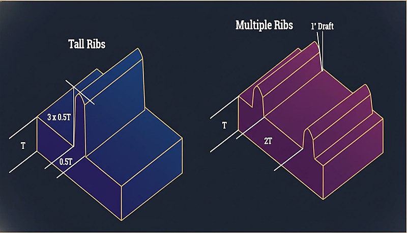
一般的な設計ガイドラインとして、リブの高さは公称肉厚の3倍を超えてはなりません。高いリブは充填の課題を生み出します。なぜなら、溶融プラスチックが狭く深いチャネルに流れ込む必要があり、そこは急速に冷却され、空気を閉じ込めたりショートショットを発生させたりする可能性があるからです。構造解析で、肉厚の3倍の高さの標準リブでは不十分な剛性が必要とされる場合、より良いアプローチは、適切な間隔を空けた複数の短いリブを使用することです。これにより、補強がより均等に分散され、射出成形プロセス中の確実な充填が維持されます。

リブ設計の専門的なDFMレビューが必要ですか?ZetarMoldのエンジニアリングチームは、部品形状を分析し、材料に特化したリブの比率を推奨し、金型投資前にモールドフローシミュレーションを実行できます。400種類以上の材料での20年以上の経験を活かし、設計上の問題を早期に発見し、時間と金型コストを節約します。

無料見積もりとDFM分析を依頼する →

射出成形のための高さのあるリブと複数リブの設計比較
複数リブ設計の比較

  1. DFMガイドライン: DFMガイドラインは、射出成形における製造性のための肉厚、リブ、ボス、抜き勾配をカバーする包括的な設計ガイドを指します。

  2. 収縮基準: ISO 294-4は、熱可塑性成形材料の収縮率を決定する方法を規定する国際規格を指します。

  3. Moldflow simulation: モールドフロー解析は、製造前に充填パターン、収縮、反り、および潜在的な欠陥を予測するために使用される業界標準のシミュレーションソフトウェアを指します。

最新の投稿
フェイスブック
ツイッター
LinkedIn
ピンタレスト
Mike Tangの写真
マイク・タン

Hi, I'm the author of this post, and I have been in this field for more than 20 years. and I have been responsible for handling on-site production issues, product design optimization, mold design and project preliminary price evaluation. If you want to custom plastic mold and plastic molding related products, feel free to ask me any questions.

私とつながる

クイック見積もり

図面および詳細要件を下記までお送りください。 

Emial:[email protected]

または下記のお問い合わせフォームにご記入ください:

クイック見積もり

図面および詳細要件を下記までお送りください。 

Emial:[email protected]

または下記のお問い合わせフォームにご記入ください:

クイック見積もり

図面および詳細要件を下記までお送りください。 

Emial:[email protected]

または下記のお問い合わせフォームにご記入ください:

クイック見積もり

図面および詳細要件を下記までお送りください。 

Emial:[email protected]

または下記のお問い合わせフォームにご記入ください:

クイック見積もり

図面および詳細要件を下記までお送りください。 

Emial:[email protected]

または下記のお問い合わせフォームにご記入ください:

ブランドのクイック見積もり

図面および詳細要件を下記までお送りください。 

Emial:[email protected]

または下記のお問い合わせフォームにご記入ください:

Спроситебыструюцитату。

Мы свяжемся с вами в течение одного рабочего дня, обратите внимание на письмо с суффиксом "[email protected]".

クイック見積もり

図面および詳細要件を下記までお送りください。 

Emial:[email protected]

または下記のお問い合わせフォームにご記入ください:

クイック見積もり

図面および詳細要件を下記までお送りください。 

Emial:[email protected]

または下記のお問い合わせフォームにご記入ください: