 Ir al contenido

El diseño de nervaduras no es solo una regla geométrica en el moldeo por inyección; es un problema de comportamiento del material. ABS, PC, PP, nailon, POM y resinas cargadas con vidrio se contraen, enfrían y resisten el estrés de manera diferente, por lo que la misma nervadura que funciona en un polímero puede crear marcas de hundimiento, alabeo o daños de expulsión en otro. Por eso el espesor, la altura, el radio de la raíz, el ángulo de desmoldeo y la posición de la entrada deben verificarse según la familia de resina antes de que el acero del molde sea cortado, muestreado, probado y validado adecuadamente.
Para compradores e ingenieros, el objetivo práctico es simple: usar nervaduras para añadir rigidez sin crear una masa gruesa en la intersección de la pared. En nuestras revisiones de DFM de moldes, primero identificamos si la resina es amorfa, semicristalina, elastomérica o cargada, luego ajustamos la relación nervadura-pared y la estrategia de enfriamiento en función de ese comportamiento. Este artículo explica cómo las propiedades del material cambian las decisiones de diseño de nervaduras y cómo evitar los defectos más comunes de herramienta y moldeo.
- Rib thickness must be 40-75% of nominal wall thickness depending on polymer type
- Semi-crystalline materials require thinner ribs due to higher shrinkage rates
- Glass-filled polymers allow thicker ribs but create anisotropic shrinkage challenges
- Sink mark severity depends on the intersection mass and material cooling behavior
- Draft angles of 0.5-1.5 per side are essential for clean rib ejection
What Are the Material Constraints for Rib Geometry?
Las restricciones de material para la geometría de la nervadura son la tasa de contracción de la resina, el perfil de enfriamiento, el objetivo de rigidez, la fricción de expulsión y el riesgo de hundimiento cosmético.
En moldeo por inyección, a rib is a thin reinforcing feature that projects perpendicular from a nominal wall to increase stiffness without adding the weight and cycle-time penalty of a uniformly thicker wall. The fundamental challenge: every rib creates a localized mass buildup where it meets the wall, and that extra mass drives shrinkage-related cosmetic defects.
When the molten polymer at the rib-wall intersection cools, the thicker cross-section stays liquid longer than the surrounding skin. As the core finally solidifies and contracts, it pulls the already-frozen outer surface inward — producing a visible sink mark on the Class A surface opposite the rib. The severity of this defect is not a constant; it depends almost entirely on the material’s internal structure and its shrinkage behavior.
In our Shanghai factory, we run 47 injection molding machines from 90T to 1850T, and we’ve processed over 400 different plastic materials. That breadth of experience means we’ve seen firsthand how a rib designed for ABS will fail catastrophically in PP if the thickness ratio isn’t adjusted — the same nominal geometry can produce a barely visible sink mark in one material and a deep groove in another.
Amorphous polymers (ABS, PC, PMMA) exhibit low, nearly isotropic shrinkage (typically 0.2-0.8%). Their random molecular arrangement means they contract relatively uniformly. This gives designers a bit more leeway — ribs can be 50-70% of wall thickness without severe sink.
Semi-crystalline polymers (PP, PE, PA6, PA66) are a different story. As they cool, their molecules fold into ordered crystalline structures that pack more tightly, producing much higher shrinkage — often 1.0-3.0%. This demands thinner ribs (40-50% of wall thickness) and more careful gating to control flow-induced orientation.
“Ribs significantly increase part stiffness with minimal weight addition compared to increasing the entire wall thickness.”Verdadero
Ribs increase the moment of inertia, providing targeted reinforcement without the material cost, cooling time penalty, and sink risk of a uniformly thicker wall.
“You can safely design ribs at the same thickness as the nominal wall to maximize structural strength.”Falso
Ribs equal to wall thickness create a massive thermal hotspot at the intersection, guaranteeing sink marks on the cosmetic surface and potentially creating internal voids.
How Do Shrinkage Rates Differ by Material Family?
The relationship between material shrinkage and rib geometry is not linear — it’s a system-level constraint. Following established DFM guidelines1 and international shrinkage standards2, the table below provides recommended design parameters by polymer family. These values represent starting points; always verify through Moldflow simulation3 for your specific part geometry and gate location.
| Parámetro | Amorphous (PC, ABS) | Semi-Crystalline (PP, PA6) | Glass-Filled (PA66-GF30) |
|---|---|---|---|
| Rib/Wall Ratio | 50-70% | 40-50% | 55-75% |
| Índice de contracción | 0.2-0.8% | 1.0-3.0% | 0.2-0.8% (anisotropic) |
| Ángulo de calado | 0.5-1.0 per side | 0.5-1.5 per side | 1.0-2.0 per side |
| Radio de la base | 0.25 × t(wall) | 0.20 × t(wall) | 0.25 × t(wall) |
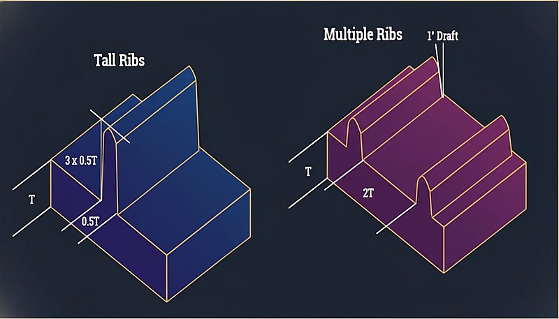
| Max Rib Height | 3 × t(wall) | 2.5 × t(wall) | 3 × t(wall) |
| Sink Risk | Low-Medium | Alta | Low (but warp risk) |
Notice the glass-filled column: glass fibers dramatically reduce volumetric shrinkage in the flow direction, but they barely affect transverse shrinkage. This anisotropic behavior means the part may not sink, but it can warp significantly if the rib layout doesn’t account for directional shrinkage. In practice, we always run a fill + pack + warp simulation for glass-filled materials before committing to tool steel.
Why Do Amorphous and Crystalline Polymers Need Different Rib Strategies?
Los polímeros amorfos y cristalinos se manejan con diferentes estrategias de nervaduras porque se congelan, contraen y mantienen la presión de empaquetado de manera distinta. Los materiales amorfos pasan gradualmente de líquido a sólido, por lo que no hay un cambio de fase brusco. Esta congelación gradual significa que la unión nervadura-pared tiene más tiempo para igualar la presión, lo que resulta en menos contracción diferencial. Puedes acercar el espesor de la nervadura al 70% del espesor de la pared sin consecuencias antiestéticas.
Semi-crystalline polymers undergo a sharp crystallization event at a specific temperature. When crystallization hits, the material contracts aggressively. If the rib base is too thick, the crystallization shrinkage in that localized zone overwhelms the packing pressure that was holding the surface flat. Result: a deep, visible sink mark that no amount of packing pressure can fix after the gate freezes.
¿Por qué los materiales rellenos de vidrio requieren ángulos de desmoldeo más grandes en las nervaduras?
“Increasing packing pressure alone cannot eliminate sink marks caused by oversized ribs in high-shrinkage crystalline materials.”Verdadero
Once the gate freezes off, no additional pressure reaches the thick section. The only effective fix is reducing the rib-wall thickness ratio to match the material’s shrinkage characteristics.
“Glass-filled materials always produce better rib outcomes because their overall shrinkage is lower.”Falso
While glass fibers reduce overall shrinkage, they create strong anisotropic effects. Ribs may not sink, but differential shrinkage between flow and transverse directions can cause significant warpage.
What Are the Practical Design Rules for Each Material?
Theory is useful, but on the shop floor, designers need actionable rules. Here’s what we apply in our DFM reviews based on the specific polymer a customer selects:
For ABS and PC (amorphous): Rib thickness = 50-70% of nominal wall. Minimum draft = 0.5 per side. Base radius = 0.25 × wall thickness. These materials are forgiving — you can push toward 70% if the opposite surface is non-cosmetic.
For PP and HDPE (semi-crystalline, unfilled): Rib thickness = 40-50% of wall. Minimum draft = 1.0 per side. Base radius = 0.20 × wall (smaller radius to minimize mass accumulation). These materials will show sink if you exceed 50% — there is no magic processing trick to fix an oversized rib in PP.
For PA66-GF30 (glass-filled): Rib thickness = 55-75% of wall. Draft = 1.0-2.0 per side (glass fibers increase ejection friction). The reduced shrinkage allows thicker ribs, but you must gate to minimize flow-length variation across ribs, or warpage will be your problem instead of sink.
Para molde de inyección designs using PC/ABS blends: Treat these as amorphous — the PC component dominates the shrinkage behavior. Rib ratios of 55-65% of wall thickness are the sweet spot. These blends are common in consumer electronics housings where both strength and surface quality matter.
How Should You Execute the Rib Design Process Step by Step?
El proceso de diseño de nervaduras es una secuencia controlada de DFM: definir cargas, bloquear datos de resina, dimensionar nervaduras, verificar espaciado, simular y luego revisar con el moldeador. Este es el flujo de trabajo que seguimos para cada pieza nueva con nervaduras estructurales:
Step 1 — Define structural requirements: Determine the stiffness targets and load cases. Calculate the required moment of inertia, then work backward to estimate rib height and spacing rather than guessing.
Step 2 — Select material and lock shrinkage data: Get the actual shrinkage values from the material datasheet for your specific grade and wall thickness. Don’t use generic values — PA66-GF30 from different suppliers can vary by 0.2-0.4% in shrinkage.
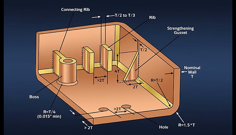
Step 3 — Calculate rib proportions: Apply the material-specific rib/wall ratio from the table above. If the wall is 2.5mm and you’re using PP, the rib base should be 1.0-1.25mm (40-50%). Set draft at 1.0 per side and base radius at 0.5mm.
Step 4 — Check rib spacing: Maintain at least 2× (preferably 3×) the wall thickness between adjacent ribs. Tighter spacing causes thin-wall filling problems and amplifies differential cooling.
Step 5 — Run Moldflow simulation: Simulate fill, pack, and warp. Look specifically at volumetric shrinkage at the rib-wall intersection and deflection results. This is where you catch problems before spending five figures on tooling.
Step 6 — DFM review with your molder: Share the simulation results with your injection molding partner. A good molder will challenge the rib layout based on their process window — packing pressure capability, cooling channel access, and ejection strategy all affect whether a rib design works in practice.
What Real-World Applications Demonstrate Material-Specific Rib Design?
Las aplicaciones de nervaduras en el mundo real son útiles porque cada familia de materiales expone un modo de fallo diferente: hundimiento, alabeo, arrastre de expulsión o desequilibrio de enfriamiento. Automotive interior brackets (PP + Talc): We regularly produce dashboard support brackets in talc-filled PP. The talc reduces shrinkage slightly compared to unfilled PP, but the crystalline nature still demands ribs at 40-45% of wall thickness. A typical 2.0mm wall gets 0.8-0.9mm ribs with 1.0 draft per side.
Laptop housings (PC/ABS): Consumer electronics demand Class A surfaces with zero visible sink. The amorphous PC/ABS blend allows ribs at 60% of the 2.2mm wall (about 1.3mm base), and we use localized thin-wall sections behind cosmetic areas to further reduce sink visibility.
Industrial enclosures (PA66-GF30): Glass-filled nylon enclosures carry high structural loads. The ribs can be 65-70% of wall thickness thanks to low shrinkage, but warpage is the real enemy. We use balanced gate placement and fiber-orientation simulation to keep flat surfaces flat.
Material handling crates (HDPE): Deep-draw crates in HDPE use aggressive rib networks. The high shrinkage of HDPE (2.0-3.0%) means ribs must be thin — typically 40% of wall — but the non-cosmetic nature of these parts means moderate sink is acceptable, allowing designers to push the ratio slightly higher.
Preguntas frecuentes
What is the maximum rib height allowed in injection molding?
Complete elimination of sink marks is extremely difficult for semi-crystalline materials when ribs exceed 45 percent of wall thickness. For amorphous polymers like PC and ABS, keeping ribs at or below 50 percent of wall thickness typically produces no visible sink on the cosmetic surface. Processing adjustments such as higher packing pressure, extended hold time, and increased cooling can reduce sink severity, but they cannot overcome a fundamentally oversized rib geometry. The most effective and reliable approach is to design the rib thickness correctly from the start based on the specific material family being used.
Can you eliminate sink marks on ribs completely?
Glass-filled materials allow thicker ribs at 55 to 75 percent of wall thickness due to the dramatically reduced volumetric shrinkage that glass fibers provide. However, they introduce significant anisotropic warpage risks because fibers orient in the flow direction and reduce shrinkage along that axis while doing little in the transverse direction. Unfilled semi-crystalline materials require thinner ribs at 40 to 50 percent to avoid sink marks, but their warpage behavior is more predictable. For glass-filled parts, always gate to minimize flow-length variation across the rib network, and run a dedicated warp simulation before committing to expensive tooling modifications.
How does rib design differ for glass-filled versus unfilled materials?
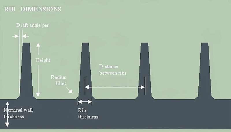
The base radius in rib design serves two critical and complementary functions. First, it reduces stress concentration at the sharp rib-wall junction, which directly improves the structural performance and fatigue life of the finished part under repeated loading. Second, it controls the amount of mass accumulation at that intersection point. The standard recommendation is a radius of 0.20 to 0.25 times the nominal wall thickness. Going larger adds excessive material and increases the risk of sink marks, while going smaller creates a stress riser that can lead to premature crack initiation and part failure under mechanical load.
What role does the base radius play in rib design?
In most practical applications, perpendicular ribs provide the highest stiffness-to-weight ratio and are the default choice for structural reinforcement. However, angled or curved ribs are sometimes used for aesthetic integration in consumer products, or to follow natural stress paths in complex load-bearing geometries such as automotive brackets. The critical constraint remains identical regardless of orientation: the cross-sectional thickness at the rib-wall intersection must respect the material-specific rib-to-wall thickness ratio to prevent sink marks and ensure the part meets both cosmetic and structural requirements.
Should ribs always be perpendicular to the nominal wall?
Coring and rib design work together as a paired strategy to optimize part weight and structural performance. Coring removes thick, unnecessary sections of a part and replaces them with a thinner wall that is then reinforced by a network of strategically placed ribs. This combination reduces raw material consumption, significantly shortens cooling time, and improves overall dimensional stability. The key principle is to establish the cored wall thickness first, then size every rib as a ratio of that new thinner wall dimension rather than the original thicker section that was removed.
How do coring and rib design work together?
Glass fibers at and near the surface of the molded part create extremely high friction against the polished mold wall during ejection. In rib features specifically, this friction problem is amplified because the rib forms a deep, narrow cavity with limited draft relief. Without sufficient draft angles — typically 1.0 to 2.0 degrees per side for glass-filled materials versus 0.5 to 1.0 for unfilled grades — the ribs can scuff, bend, or fracture during ejection. This not only damages the part cosmetically and structurally but can also degrade the mold surface over thousands of production cycles.
Why do glass-filled materials require larger draft angles on ribs?
Cómo las Propiedades del Material Influyen en el Diseño de Nervaduras en el Moldeo por Inyección
Need expert DFM review for your rib design? ZetarMold’s engineering team can analyze your part geometry, recommend material-specific rib proportions, and run Moldflow simulations before you invest in tooling. With 20+ years of experience across 400+ materials, we catch design issues early — saving you time and tooling costs.
Request a Free Quote and DFM Analysis →
-
DFM guidelines: DFM guidelines refers to comprehensive design guides covering wall thickness, ribs, bosses, and draft angles for manufacturability in injection molding. ↩
-
shrinkage standards: ISO 294-4 refers to international standard specifying methods for determining shrinkage of thermoplastic molding materials. ↩
-
Moldflow simulation: Moldflow analysis refers to industry-standard simulation software used to predict filling patterns, shrinkage, warpage, and potential defects before manufacturing. ↩


