 콘텐츠로 건너뛰기

An 사출 금형1 is not a single block of metal — it is a precision assembly of several interconnected systems, each with a specific job. Get any one of them wrong, and you end up with flash, sink marks, short shots, or worse: a mold that costs five figures to fix. In our factory in Shanghai, we have built thousands of molds over 20+ years, and the lesson is always the same: understanding every main part of the mold is the difference between a smooth production run and a costly nightmare.
- An injection mold has 6 core functional systems: gating, molding, temperature control, structural, ejection, and exhaust.
- The gating system controls how molten plastic enters the cavity — gate size and location directly affect part quality.
- Molding parts (core and cavity) define the shape, surface finish, and dimensional accuracy of the final product.
- Temperature control via cooling channels determines cycle time and prevents warpage.
- Proper ejection system design avoids part deformation and ensures consistent demolding.
This guide breaks down each main part of the injection mold, explains how they work together, and shares practical tips from real production experience. Whether you are specifying a new mold or troubleshooting an existing one, knowing these systems inside out will save you time and money.
What Is an Injection Mold and Why Does Its Structure Matter?
An injection mold and why does its structure matter is defined by the function, constraints, and tradeoffs explained in this section. If you are comparing vendors or planning procurement, our injection molding supplier sourcing guide covers RFQ prep, qualification, and commercial risk checks.
An injection mold is a custom-manufactured tool that shapes molten plastic into a specific geometry under high pressure and temperature. It consists of two primary halves — the fixed half (A-side or cavity side) mounted on the stationary platen, and the moving half (B-side or core side) mounted on the moving platen of the 사출 성형 machine. When these two halves close, they form a sealed cavity where the plastic part takes shape.
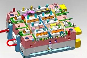
The structure of an injection mold is far more complex than it appears. A typical production mold contains 100–300 individual components, organized into functional systems. Each system must work in perfect coordination: the gating system2 delivers material, the molding parts define geometry, the cooling system solidifies the part, the ejection system removes it, the guide system ensures alignment, and the exhaust system vents trapped air and gases.
In our Shanghai factory, we run 47 injection molding machines from 90T to 1850T and maintain an in-house mold manufacturing facility. With 20+ years of experience, we have learned that mold structure decisions made during the design phase determine 70–80% of final part quality.
Why does mold structure matter so much? Because every design choice cascades through production. Gate location affects weld line position. Cooling channel layout determines cycle time and warpage. Ejection pin placement influences cosmetic quality. A well-structured mold runs reliably for hundreds of thousands of cycles; a poorly structured one becomes a constant source of defects and downtime.

What Are the Functional Systems of an Injection Mold?
The functional systems of an injection mold are the main categories or options explained in this section. Before diving into each part, it helps to see the big picture. An injection mold is organized into six functional systems, each responsible for a critical phase of the molding cycle. The table below summarizes these systems and their primary components.
| System | Primary Function | Key Components |
|---|---|---|
| 게이팅 시스템 | Channels molten plastic from nozzle to cavity | Sprue, runners, gates, cold slug well |
| 성형 부품 | Defines the shape and surface of the part | Core, cavity, inserts, sliders |
| 온도 제어 | Regulates mold temperature for cooling/heating | Cooling channels, water lines, heating rods |
| 구조 부품 | Supports and aligns all mold components | Mold base, guide pins, guide bushings, plates |
| 배출 시스템 | Removes the finished part from the mold | Ejector pins, ejector plates, return pins, springs |
| 배기 시스템 | Vents trapped air and gases from the cavity | Vent grooves, parting surface vents, ejector pin clearance |
Among these, the gating system and molding parts are in direct contact with the molten plastic. They are the most complex and variable components, requiring the highest machining precision and surface finish. The gating system² directly affects filling pattern, pressure distribution, and weld line formation. The molding parts determine dimensional accuracy, surface quality, and part strength.
How Does the Gating System Work in an Injection Mold?
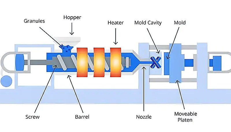
The gating system is the pathway that molten plastic travels from the nozzle of a 스크류 사출 성형기 into the mold cavity. It consists of four main elements: the sprue (main runner), branch runners, gates, and cold slug wells. Each element plays a distinct role in controlling material flow, pressure, and part quality. In our factory trials, we validate this path against the 사출 성형 단계 so filling, packing, cooling, and ejection stay balanced.
그리고 sprue is the vertical channel that connects the machine nozzle to the runner system. Its inlet diameter is typically 0.8 mm larger than the nozzle tip diameter to prevent flash and ensure proper alignment. A standard sprue inlet ranges from 4–8 mm depending on part size, with a 3°–5° 구배 각도3 for easy removal of the solidified sprue.
그리고 branch runners distribute material from the sprue to individual cavities in multi-cavity molds. For balanced filling, runners should be arranged symmetrically and equidistantly. Cross-sectional shape matters: round runners offer the lowest flow resistance, but trapezoidal runners are more common because they are machined into only one mold half, reducing manufacturing cost. Runner width for most thermoplastics stays between 2–8 mm.
그리고 게이트 is the narrowest point in the runner system and the entry point into the cavity. Gate design is one of the most critical decisions in mold engineering. A small gate increases shear heating (which lowers melt viscosity and improves flow), controls flow rate, and makes it easier to separate the part from the runner. However, if the gate is too small, it causes excessive shear stress and visible gate marks. Common gate types include edge gates, submarine gates, pin gates, and fan gates — each suited to different part geometries and materials.
그리고 콜드 슬러그 웰 sits opposite the sprue and catches the cold plastic that forms at the nozzle tip between shots. If this cold material enters the cavity, it causes surface defects and weak weld lines. A typical cold slug well has a diameter of 8–10 mm and a depth of 6 mm, often with a zigzag or undercut puller to help extract the sprue during mold opening.
“A smaller gate size increases shear heating, which can improve melt flow into the cavity.”True
맞습니다. 용융물이 좁은 게이트를 통과할 때, 높은 전단율이 마찰열을 발생시켜 국부 용융 온도를 상승시키고 점도를 감소시킵니다. 이는 캐비티 충전을 개선하며, 특히 점성 재료에 유리합니다. 그러나 게이트가 너무 작으면 과도한 전단 분해로 인해 고분자가 열화될 수 있습니다.
“원형 러너 단면은 항상 최선의 선택입니다. 왜냐하면 가장 낮은 유동 저항을 가지기 때문입니다.”False
틀립니다. 원형 러너는 주어진 단면적에 대해 가장 낮은 유동 저항을 제공하지만, 두 금형 반쪽에 가공되어야 하며 정밀한 정렬이 필요합니다. 실제로는 사다리꼴 또는 변형 U자형 러너가 한쪽 반쪽에만 절삭되어 제조 비용과 정렬 복잡성을 줄이기 때문에 종종 선호됩니다.
What Role Do Molding Parts Play in Shaping the Product?
성형 부품(캐비티와 코어라고도 함)은 모든 사출 금형의 핵심입니다. cavity (다이 또는 암컷 금형이라고도 함) 제품의 외부 형상을 형성합니다. 라인이 비중요 표면에 위치하고 밀봉, 조립, 냉각 및 금형 강도를 보호한다면, 그것을 취약하거나 비싼 공구 위치에 숨기는 것보다 더 나을 수 있습니다. (남성 금형 또는 펀치라고도 함)는 구멍, 리브 및 포켓과 같은 내부 특징을 형성합니다. 금형이 닫히면 코어와 캐비티 사이의 간격이 완성된 부품의 정확한 모양이 됩니다.
성형 부품 설계에는 여러 결정이 포함됩니다: 파팅 라인³ 위치, 표면 마감 요구 사항, 이젝션을 위한 드래프트 각도⁵ 및 재료 선택. 파팅 라인은 언더컷 특징을 최소화하고 깨끗한 이젝션을 허용하도록 배치되어야 합니다. 성형 표면의 표면 마감은 일반적으로 광택 처리된 코스메틱 부품의 경우 Ra 값이 0.32 μm 미만이어야 합니다 — 더 거칠면 표면 질감이 성형된 제품에 직접 전달됩니다.
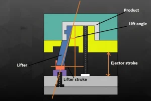
복잡한 형상의 경우, 성형 부품에는 종종 인서트 (기계 가공이 어려운 특징을 위한 제거 가능한 블록), 슬라이더 (언더컷 및 측면 특징을 위한 이동 코어), 그리고 각도 리프터 (내부 언더컷용). 이러한 구성 요소는 비용과 복잡성을 증가시키지만, 일반적인 드로우 방향으로 성형할 수 없는 나사산, 스냅 피트 또는 측면 구멍이 있는 부품을 생산하는 데 필수적입니다.
8명의 선임 엔지니어와 월 100개 이상의 금형 세트를 제작할 수 있는 역량을 갖춘 당사 팀은 400종 이상의 플라스틱 소재에 걸쳐 성형 부품 설계에 대한 깊은 경험을 보유하고 있습니다. 각 소재의 수축률, 유동 특성 및 냉각 거동은 코어와 캐비티 설계 방식에 영향을 미칩니다.
성형 부품의 재료 선택도 동등하게 중요합니다. 대부분의 생산 금형은 경화된 공구강(P20, H13, S136 또는 718H)을 적절한 열처리로 48–54 HRC 경도를 달성하여 사용합니다. 대량 생산이나 마모성 재료의 경우, 금형 표면에 TiN(티타늄 질화물) 또는 크롬 도금과 같은 추가 코팅을 적용하여 내마모성과 내식성을 향상시킬 수 있습니다.
Why Is the Temperature Control System Critical?
온도 제어 시스템은 비용, 품질, 생산량 및 적용 분야의 절충점을 고려할 때 중요합니다. 온도 제어 시스템은 종종 간단히 냉각 시스템 — 각 주기 동안 금형의 작동 온도를 조절합니다. 대부분의 열가소성 사출 금형의 경우 주요 기능은 냉각입니다: 녹은 플라스틱에서 열을 제거하여 변형 없이 이젝션될 수 있는 안정적인 부품으로 응고시킵니다.
냉각은 일반적으로 사출 성형 주기에서 가장 긴 단계로, 전체 주기 시간의 50~70%를 차지합니다. 냉각 효율의 작은 개선도 직접적으로 더 높은 생산량과 부품당 낮은 비용으로 이어집니다. 가장 일반적인 접근 방식은 제어된 온도의 순환수를 통한 금형 플레이트에 드릴된 냉각 채널(워터 라인) 네트워크를 사용합니다. 냉각 채널 (워터 라인)이 금형 플레이트에 드릴되어 제어된 온도의 순환수를 통해 냉각됩니다.
주요 냉각 채널 구성에는 직선 드릴 채널(가장 간단하고 저렴한), 배플 (블라인드 홀 안으로 흐름을 재지향하는 편향기), 버블러 (코어 핀 주변에 환형 흐름을 생성하는 튜브), 그리고 conformal cooling channels (균일한 냉각을 위해 캐비티 윤곽을 따르는 3D 프린팅 채널). 컨포멀 냉각은 기존 드릴 채널에 비해 사이클 시간을 20~40% 줄일 수 있지만, 금형 비용을 크게 증가시킵니다.
경우에 따라, 금형은 실제로 필요로 합니다 가열 냉각이 아닌. 폴리카보네이트, PEEK 및 특정 엔지니어링 플라스틱과 같은 재료는 조기 동결을 방지하고 잔류 응력을 줄이며 적절한 결정성을 달성하기 위해 높은 금형 온도(80~180°C)가 필요합니다. 핫 러너 시스템과 카트리지 히터가 이러한 응용 분야에 사용됩니다.
“대부분의 응용 분야에서 냉각은 전체 사출 성형 사이클 시간의 50–70%를 차지합니다.”True
사실입니다. 캐비티가 채워지고 압축된 후, 부품은 뒤틀림이나 변형 없이 이젝션될 수 있을 만큼 충분히 냉각되어야 합니다. 이 응고 단계는 일반적으로 사이클에서 가장 긴 부분입니다. 냉각 채널 설계(배치, 유량 및 온도)를 최적화하는 것은 생산 처리량을 높이는 가장 효과적인 방법 중 하나입니다.
“모든 사출 금형은 냉각 채널만 필요하며, 가열은 절대 필요하지 않습니다.”False
틀립니다. 폴리카보네이트, PEEK, 나일론과 같은 많은 엔지니어링 열가소성 수지는 적절한 결정화도와 잔류 응력 감소를 위해 높은 금형 온도가 필요합니다. 이러한 경우, 온도 제어 시스템에는 냉각수와 함께 또는 대신 카트리지 히터나 열매 순환과 같은 가열 요소가 포함됩니다.
How Do Structural Parts Support the Mold?
이 섹션은 금형을 지지하는 구조 부품과 비용, 품질, 타이밍 또는 조달 위험에 미치는 영향에 관한 것입니다. 구조 부품은 금형의 중추를 형성합니다. 모든 것을 함께 고정하고, 금형 반쪽 사이의 정밀한 정렬을 보장하며, 사출 중 발생하는 엄청난 클램핑 힘(일반적으로 기계 크기에 따라 50~200톤 이상)을 견뎌냅니다. 주요 구조 구성 요소에는 다음이 포함됩니다. mold base (표준 프레임), 가이드 핀과 부싱, 지지 기둥, 그리고 다양한 플레이트.
그리고 mold base (금형 프레임 또는 볼스터라고도 함)는 다른 모든 구성품을 수용하는 외부 구조물입니다. 대부분의 사출 금형은 설계 및 제조 시간을 줄이기 위해 표준화된 금형 베이스(DME, HASCO 또는 LKM 등)를 사용합니다. 금형 베이스는 상부 클램핑 플레이트, A-플레이트(캐비티 측), B-플레이트(코어 측), 지지 플레이트, 이젝터 하우징 및 하부 클램핑 플레이트를 포함합니다.
가이드 핀과 가이드 부싱 금형 폐쇄 시 이동측과 고정측 금형이 정확하게 정렬되도록 합니다. 표준 금형은 모서리에 위치한 네 세트의 가이드 핀과 부싱을 사용합니다. 더 높은 정밀도를 위해, 파팅 표면에 추가 테이퍼 인터록이나 제로 디그리 사이드 록이 설치됩니다. 적절한 가이드 정렬이 없으면, 코어와 캐비티가 이동하여 플래시, 치수 오류 및 가속된 마모를 유발할 수 있습니다.
기타 중요한 구조 요소에는 다음이 포함됩니다. 리턴 핀 (금형이 닫힐 때 이젝터 플레이트를 다시 밀어내는), 지지 기둥 (사출 압력 하에서 B-플레이트의 처짐을 방지하는), 그리고 스톱 블록 (올바른 금형 높이를 설정함). 이러한 각 구성품은 수백만 사이클 동안 금형 무결성을 유지하기 위해 올바르게 크기 조정되고 위치되어야 합니다.
What Makes the Ejection System Effective?
플라스틱 부품이 냉각되고 응고된 후, 금형에서 제거되어야 합니다 — 이것이 이젝션 시스템의 역할입니다. 이젝터 핀⁴이 가장 일반적인 이젝션 요소이지만, 시스템에는 이젝터 플레이트, 리턴 핀, 스프링, 스트리퍼 플레이트 및 경우에 따라 에어 블라스트 밸브나 로봇 추출도 포함됩니다.
Ejection system design must balance several competing requirements. The ejection force must be large enough to overcome the friction between the cooled plastic and the core surface, but not so large that it damages the part. Ejector pins must be placed on non-cosmetic surfaces whenever possible, or disguised as functional features (such as bosses or rib intersections). The number, diameter, and position of ejector pins are determined by the part geometry, material shrinkage behavior, and surface finish requirements.
For thin-walled or fragile parts, stripper plates are preferred over individual pins because they distribute ejection force evenly across the entire part perimeter. For parts with deep cores or significant undercut, sleeve ejectors 또는 각도 리프터 may be necessary. In all cases, the ejection system must work smoothly at production speed — any sticking or inconsistent ejection causes downtime and scrap.
Our 90T to 1850T machine range means we produce everything from tiny precision medical components to large structural parts. Each part category demands a different ejection strategy. Working under ISO 9001 and ISO 13485 systems ensures our ejection designs are validated before production begins.
How Do Guide and Exhaust Systems Ensure Quality?
Two systems that are easy to overlook but critical for quality: the 가이드 시스템 및 exhaust system. The guide system ensures that the moving and fixed mold halves align precisely every cycle. The exhaust system vents the air and gases that are trapped in the cavity during filling — without it, you get burns, short shots, and weak weld lines.
The guide system uses guide pins (leader pins) and guide bushings mounted on the four corners of the mold. These engage first as the mold closes, bringing the two halves into rough alignment before the core and cavity make contact. For higher precision molds, additional locating elements such as taper interlocks, straight side locks, or conical locating blocks are added at the parting surface to maintain alignment within plus or minus 0.01 mm.
The exhaust system works through shallow grooves (0.03–0.20 mm deep, 1.5–6 mm wide) machined into the parting surface, typically at the end of the melt flow path. These grooves allow trapped air and decomposition gases to escape. If exhaust is insufficient, the compressed gas heats up rapidly (adiabatic compression) and can reach temperatures that burn or discolor the plastic surface — a defect known as diesel effect or gas burn.
In addition to dedicated vent grooves, mold designers use secondary exhaust paths: the clearance between ejector pins and their holes, between sliders and their guides, and between lifters and the core. These incidental vents supplement the primary vent grooves, especially for complex parts with multiple flow fronts and weld lines.
자주 묻는 질문
What are the six main functional systems of an injection mold?
The six main systems are the gating system (delivers molten plastic), molding parts (define part geometry), temperature control system (regulates cooling and heating), structural parts (support and align the mold), ejection system (removes the finished part), and exhaust system (vents trapped air and gases). Each system must work in coordination for reliable, high-quality production. A failure in any one system — such as a blocked vent, an undersized gate, or a misaligned guide pin — can cascade into defects, downtime, and costly rework. Understanding how these systems interact is essential for specifying, reviewing, or troubleshooting injection molds.
How does the gating system affect injection molded part quality?
The gating system controls how molten plastic enters the cavity. Gate size, type, and location directly influence filling pattern, pressure distribution, weld line position, and surface appearance. An improperly designed gate can cause jetting, sink marks, flow lines, or incomplete filling. For example, a gate that is too small increases shear stress and can degrade the polymer, while a gate in the wrong location can trap air and cause gas burns. This makes gate design one of the most critical decisions in mold engineering, often validated through mold flow simulation before steel is cut.
What is the difference between a core and a cavity in a mold?
The cavity (female mold or die) forms the external shape and cosmetic surfaces of the part. The core (male mold or punch) forms the internal features such as holes, ribs, and pockets. Together, the core and cavity define the complete 3D geometry of the molded part when the mold is closed. The cavity is typically mounted on the fixed side of the mold, while the core is on the moving side where ejection occurs. Both must be machined to extremely tight tolerances — often within ±0.01 mm — to ensure part accuracy and prevent flash at the parting line.
Why is cooling channel design so important in injection molds?
Cooling typically accounts for 50–70% of the total cycle time, making it the single largest factor in production efficiency. Efficient cooling channel layout reduces cycle time, improves throughput, and prevents defects like warpage and uneven shrinkage. Advanced approaches like conformal cooling — where channels follow the cavity contour — can reduce cycle time by 20–40% compared to conventional straight-drilled channels. Poor cooling design not only slows production but also creates inconsistent part dimensions and surface quality, which is why thermal simulation is standard practice in professional mold design.
What happens if the exhaust system in a mold is insufficient?
Insufficient exhaust causes trapped air and gases to compress adiabatically, generating extreme local temperatures that can burn or discolor the plastic surface — a defect known as the diesel effect or gas burn. It also leads to short shots (incomplete filling), weak weld lines where multiple flow fronts meet, and internal voids. Proper vent grooves (0.03–0.20 mm deep) machined at the end of flow paths, combined with ejector pin clearances that act as secondary vents, prevent these issues. In multi-cavity molds, balanced exhaust across all cavities is critical for consistent part quality.
What materials are injection mold cores and cavities made from?
Most production molds use hardened tool steels such as P20, H13, S136, or 718H, heat-treated to 48–54 HRC for durability and wear resistance. P20 is the most common choice for general-purpose molds, while H13 and S136 are preferred for high-temperature or corrosive materials. For high-volume or abrasive applications, mold surfaces may receive additional coatings such as TiN (titanium nitride) or chrome plating. Prototype and short-run molds sometimes use aluminum (Al 7075) for faster machining and lower cost, though aluminum molds have significantly shorter tool life.
How many ejector pins does a typical injection mold need?
The number of ejector pins depends on part geometry, size, wall thickness, and material shrinkage behavior. A simple, small part may need only 4–8 pins, while a complex part with thin walls, deep draws, or delicate features can require 20–50 or more. The key principle is to distribute ejection force evenly across the part to prevent deformation, cracking, or sticking during demolding. For fragile parts, stripper plates or sleeve ejectors may be used instead of individual pins to provide uniform ejection force along the entire part perimeter.
Can injection molds have both heating and cooling systems?
Yes, many injection molds incorporate both heating and cooling capabilities. Engineering thermoplastics like polycarbonate, PEEK, and nylon require elevated mold temperatures (80–180°C) during filling to prevent premature freezing and achieve proper crystallinity. These molds use cartridge heaters or hot oil circulation alongside cooling water channels. During the filling and packing phases, heating maintains the mold temperature; during the cooling phase, the system may switch to active cooling to accelerate solidification. This dual-mode temperature control is standard practice in precision molding of high-performance engineering plastics.
Need a precision injection mold designed and built right the first time? Our engineering team in Shanghai has 20+ years of experience designing molds with optimized gating, cooling, and ejection systems across 400+ materials. Contact us today to discuss your next mold project — we respond within 24 hours with a detailed technical quotation. For a broader tooling overview, see our complete guide to injection mold.
-
injection mold: injection mold refers to a precision tool used in manufacturing to shape molten plastic into a desired form by injecting material under high pressure into a cavity. ↩
-
gating system: gating system refers to the network of channels in a mold that guides molten plastic from the machine nozzle into the cavity, including the sprue, runners, and gates. ↩
-
draft angle: draft angle refers to a slight taper applied to the vertical surfaces of a mold cavity to facilitate easy removal of the molded part during ejection. ↩




 EN
EN  ES
ES  FR
FR  DE
DE  PT
PT  AR
AR  RU
RU  JA
JA  KO
KO  IT
IT  NL
NL  TR
TR  PL
PL 