Un molde de inyección1 no es un único bloque de metal, sino un conjunto de precisión formado por varios sistemas interconectados, cada uno con una función específica. Si alguno falla, aparecen rebabas, rechupes, llenados incompletos o algo peor: un molde cuya reparación cuesta decenas de miles. En nuestra fábrica de Shanghái hemos construido miles de moldes durante más de 20 años, y la lección siempre es la misma: conocer todas las partes principales del molde marca la diferencia entre una producción fluida y una pesadilla costosa.
- Un molde de inyección tiene 6 sistemas funcionales principales: sistema de alimentación, moldeo, control de temperatura, estructural, eyección y escape.
- El sistema de alimentación controla cómo el plástico fundido entra en la cavidad: el tamaño y la ubicación de la compuerta afectan directamente la calidad de la pieza.
- Las piezas de moldeo (núcleo y cavidad) definen la forma, el acabado superficial y la precisión dimensional del producto final.
- El control de temperatura a través de canales de enfriamiento determina el tiempo de ciclo y evita deformaciones.
- Un diseño adecuado del sistema de eyección evita la deformación de la pieza y asegura un desmoldeo consistente.
Esta guía desglosa cada parte principal del molde de inyección, explica cómo funcionan juntas y comparte consejos prácticos de la experiencia real de producción. Ya sea que esté especificando un nuevo molde o solucionando problemas de uno existente, conocer estos sistemas a fondo le ahorrará tiempo y dinero.
¿Qué es un Molde de Inyección y por qué Importa su Estructura?
La naturaleza de un molde de inyección y la importancia de su estructura se explican mediante la función, las restricciones y las compensaciones descritas en esta sección. Si está comparando proveedores o planificando compras, nuestra guía para seleccionar proveedores de moldeo por inyección aborda la preparación de solicitudes de cotización, la homologación y la comprobación de riesgos comerciales.
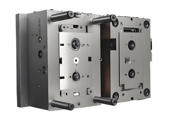
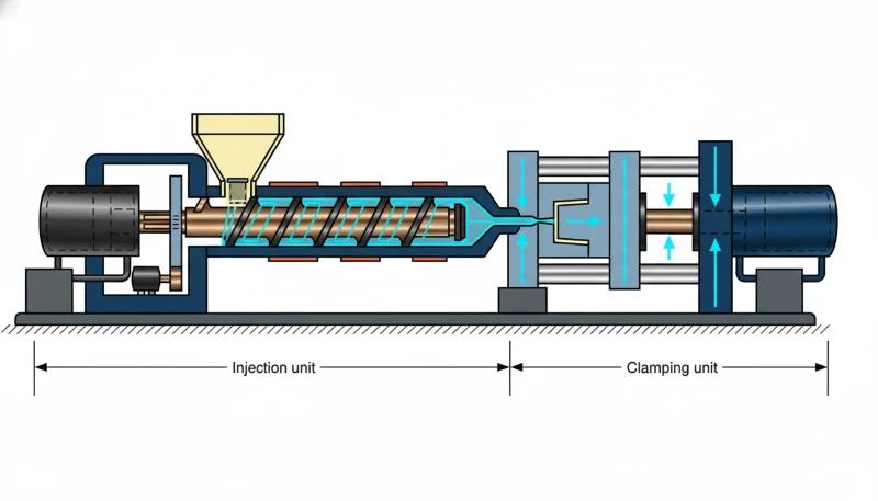
Un molde de inyección es una herramienta fabricada a medida que da una geometría concreta al plástico fundido mediante alta presión y temperatura. Consta de dos mitades principales: la mitad fija (lado A o lado de la cavidad), montada en la platina fija, y la mitad móvil (lado B o lado del núcleo), instalada en la platina móvil de la máquina de moldeo por inyección. Al cerrarse, ambas mitades forman una cavidad estanca en la que toma forma la pieza de plástico.
La estructura de un molde de inyección es mucho más compleja de lo que parece. Un molde de producción típico contiene entre 100 y 300 componentes individuales organizados en sistemas funcionales. Todos deben coordinarse perfectamente: el sistema de alimentación2 suministra el material, las piezas de moldeo definen la geometría, el sistema de enfriamiento solidifica la pieza, el sistema de expulsión la extrae, el sistema de guiado garantiza la alineación y el sistema de ventilación evacua el aire y los gases atrapados.
En nuestra fábrica de Shanghái, operamos 47 máquinas de moldeo por inyección de 90T a 1850T y mantenemos una instalación interna de fabricación de moldes. Con más de 20 años de experiencia, hemos aprendido que las decisiones sobre la estructura del molde tomadas durante la fase de diseño determinan el 70–80% de la calidad final de la pieza.
¿Por qué es tan importante la estructura del molde? Porque cada elección de diseño se propaga a lo largo de la producción. La ubicación de la compuerta afecta la posición de la línea de soldadura. El diseño de los canales de refrigeración determina el tiempo de ciclo y la deformación. La colocación de los eyectores influye en la calidad cosmética. Un molde bien estructurado funciona de manera confiable durante cientos de miles de ciclos; uno mal estructurado se convierte en una fuente constante de defectos y tiempo de inactividad.
¿Cuáles son los sistemas funcionales de un molde de inyección?
Los sistemas funcionales de un molde de inyección son las categorías principales u opciones explicadas en esta sección. Antes de profundizar en cada parte, ayuda ver el panorama general. Un molde de inyección se organiza en seis sistemas funcionales, cada uno responsable de una fase crítica del ciclo de moldeo. La tabla siguiente resume estos sistemas y sus componentes principales.
| Sistema | Función principal | Componentes clave |
|---|---|---|
| Sistema de compuertas | Canaliza el plástico fundido desde la boquilla hasta la cavidad | Bebedero, canales, compuertas, pozo de material frío |
| Piezas de moldeo | Define la forma y superficie de la pieza | Núcleo, cavidad, insertos, correderas |
| Control de la temperatura | Regula la temperatura del molde para enfriar/calentar | Canales de enfriamiento, líneas de agua, varillas calefactoras |
| Piezas estructurales | Soporta y alinea todos los componentes del molde | Base del molde, pasadores guía, bujes guía, placas |
| Sistema de eyección | Extrae la pieza terminada del molde | Eyectores, placas eyectoras, pasadores de retorno, resortes |
| Sistema de escape | Ventila el aire y los gases atrapados en la cavidad | Ranuras de ventilación, ventilaciones en la superficie de partición, holgura del pasador eyector |
Entre estos, el sistema de colada² y las piezas de moldeo están en contacto directo con el plástico fundido. Son los componentes más complejos y variables, que requieren la mayor precisión de mecanizado y acabado superficial. El sistema de colada² afecta directamente el patrón de llenado, la distribución de presión y la formación de líneas de soldadura. Las piezas de moldeo determinan la precisión dimensional, la calidad superficial y la resistencia de la pieza.
¿Cómo funciona el sistema de alimentación en un molde de inyección?
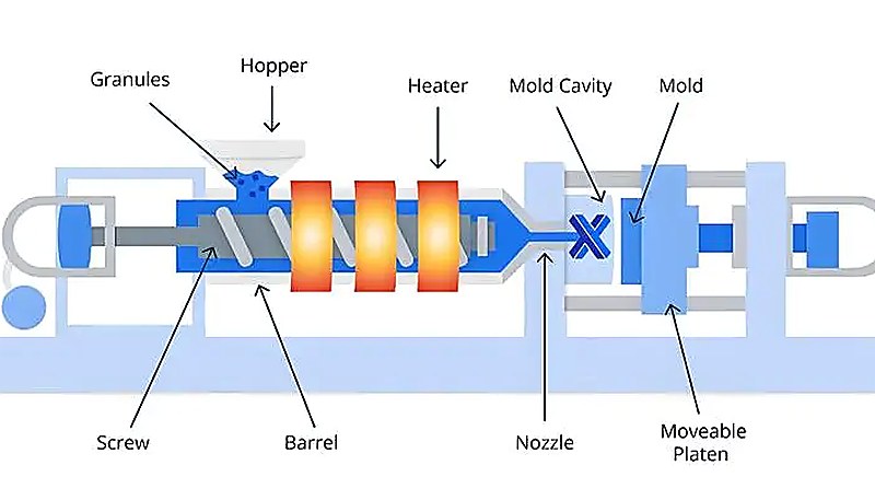
El sistema de alimentación es el recorrido que sigue el plástico fundido desde la boquilla de una máquina de moldeo por inyección de husillo hasta la cavidad del molde. Consta de cuatro elementos principales: el bebedero (canal principal), los canales secundarios, las entradas y los pozos fríos. Cada elemento cumple una función distinta en el control del flujo del material, la presión y la calidad de la pieza. En nuestras pruebas de fábrica, validamos este recorrido con respecto a las etapas del moldeo por inyección para mantener equilibrados el llenado, la compactación, el enfriamiento y la expulsión.
El bebedero es el canal vertical que conecta la boquilla de la máquina con el sistema de canales. El diámetro de entrada suele ser 0,8 mm mayor que el diámetro de la punta de la boquilla para evitar rebabas y garantizar una alineación correcta. Una entrada de bebedero estándar mide entre 4 y 8 mm según el tamaño de la pieza y presenta un ángulo de desmoldeo3 de 3°–5° para facilitar la extracción del bebedero solidificado.
Los canales secundarios distribuyen el material desde el bebedero hasta cada cavidad en los moldes multicavidad. Para lograr un llenado equilibrado, deben disponerse de forma simétrica y equidistante. La sección transversal es importante: los canales redondos ofrecen la menor resistencia al flujo, pero los trapezoidales son más habituales porque solo se mecanizan en una mitad del molde, lo que reduce el coste de fabricación. En la mayoría de los termoplásticos, la anchura de los canales se mantiene entre 2 y 8 mm.
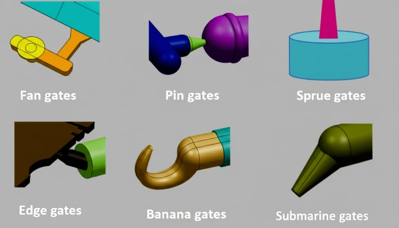
La entrada es el punto más estrecho del sistema de canales y el acceso a la cavidad. Su diseño es una de las decisiones más críticas en la ingeniería del molde. Una entrada pequeña aumenta el calentamiento por cizallamiento —lo que reduce la viscosidad del fundido y mejora el flujo—, controla el caudal y facilita la separación de la pieza y el canal. Sin embargo, si es demasiado pequeña, provoca una tensión de cizallamiento excesiva y marcas visibles. Entre los tipos habituales se encuentran las entradas laterales, submarinas, puntiformes y en abanico, cada una adecuada para distintas geometrías y materiales.
El pozo frío se encuentra frente al bebedero y recoge el plástico frío que se forma en la punta de la boquilla entre ciclos. Si este material frío entra en la cavidad, provoca defectos superficiales y líneas de soldadura débiles. Un pozo frío típico tiene un diámetro de 8–10 mm y una profundidad de 6 mm, y suele incorporar un extractor en zigzag o con socavado para ayudar a retirar el bebedero al abrir el molde.
"Un tamaño de compuerta menor aumenta el calentamiento por cizallamiento, lo que puede mejorar el flujo del material fundido hacia la cavidad."True
Verdadero. A medida que el material fundido pasa por una entrada estrecha, la alta tasa de cizallamiento genera calor por fricción, elevando la temperatura local del fundido y reduciendo la viscosidad. Esto mejora el llenado de la cavidad, especialmente para materiales viscosos. Sin embargo, entradas demasiado pequeñas pueden causar una degradación excesiva por cizallamiento del polímero.
"Las secciones transversales redondas de los canales son siempre la mejor opción porque ofrecen la menor resistencia al flujo."False
Falso. Aunque los canales redondos ofrecen la menor resistencia al flujo para un área transversal dada, deben mecanizarse en ambas mitades del molde y requieren una alineación precisa. En la práctica, a menudo se prefieren los canales trapezoidales o en forma de U modificada porque se cortan solo en una mitad, reduciendo el coste de fabricación y la complejidad de alineación.
¿Qué Papel Desempeñan las Piezas de Moldeo en la Forma del Producto?
Las piezas de moldeo —también llamadas cavidades y núcleos— son el corazón de cualquier molde de inyección. La cavidad —también denominada matriz o molde hembra— forma la superficie exterior del producto. El núcleo —también llamado molde macho o punzón— forma los elementos interiores, como orificios, nervios y huecos. Cuando el molde se cierra, el espacio entre el núcleo y la cavidad reproduce exactamente la forma de la pieza terminada.
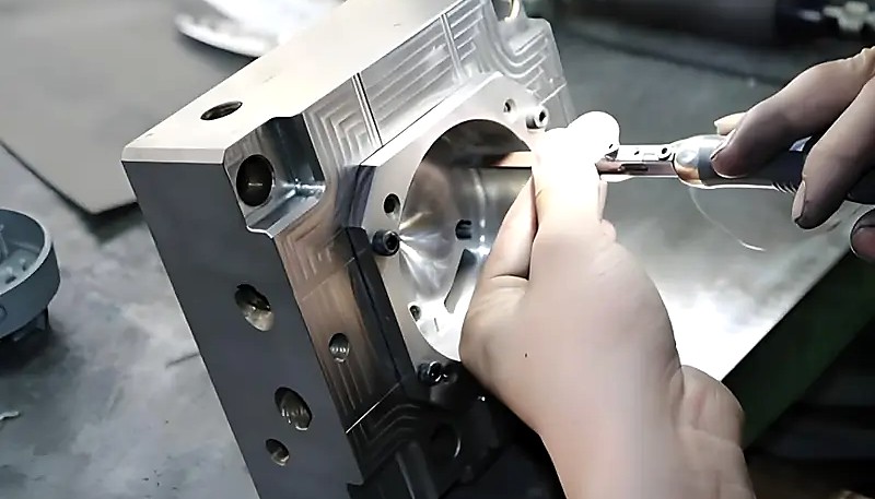
El diseño de piezas de moldeo implica múltiples decisiones: la ubicación de la línea de partición³, los requisitos de acabado superficial, los ángulos de desmoldeo⁵ para la expulsión y la selección del material. La línea de partición debe posicionarse para minimizar las características de subcorte y permitir una expulsión limpia. El acabado superficial en las superficies de moldeo normalmente requiere un valor Ra inferior a 0.32 μm para piezas cosméticas pulidas — cualquier rugosidad mayor, y la textura superficial se transfiere directamente al producto moldeado.
En geometrías complejas, las piezas de moldeo suelen incluir insertos —bloques desmontables para elementos difíciles de mecanizar—, correderas —núcleos móviles para socavados y elementos laterales— y expulsores inclinados —para socavados internos—. Estos componentes aumentan el coste y la complejidad, pero son esenciales para fabricar piezas con roscas, cierres a presión u orificios laterales que no pueden moldearse en la dirección normal de desmoldeo.
Con 8 ingenieros sénior y capacidad para fabricar 100+ juegos de moldes al mes, nuestro equipo posee amplia experiencia en el diseño de piezas moldeadas con 400+ materiales plásticos. La tasa de contracción, las características de flujo y el comportamiento de enfriamiento de cada material influyen en el diseño de núcleos y cavidades.
La selección de material para las piezas de moldeo es igualmente crítica. La mayoría de los moldes de producción utilizan acero para herramientas endurecido (P20, H13, S136 o 718H) con el tratamiento térmico adecuado para alcanzar una dureza de 48–54 HRC. Para materiales de alto volumen o abrasivos, las superficies del molde pueden recibir recubrimientos adicionales como TiN (nitruro de titanio) o cromado para mejorar la resistencia al desgaste y la protección contra la corrosión.
¿Por qué es crítico el sistema de control de temperatura?
El sistema de control de temperatura es fundamental por sus efectos sobre el coste, la calidad, el volumen y la aplicación. Este sistema —a menudo llamado simplemente sistema de enfriamiento— regula la temperatura de funcionamiento del molde durante cada ciclo. En la mayoría de los moldes de inyección de termoplásticos, su función principal es enfriar: extraer calor del plástico fundido para que se solidifique en una pieza estable que pueda expulsarse sin deformarse.
El enfriamiento suele ser la fase más larga del ciclo de moldeo por inyección y representa entre el 50 y el 70 % del tiempo total. Incluso pequeñas mejoras en su eficiencia se traducen directamente en una mayor producción y un menor coste por pieza. El método más común utiliza una red de canales de enfriamiento —conductos de agua— perforados en las placas del molde, por los que circula agua a una temperatura controlada.
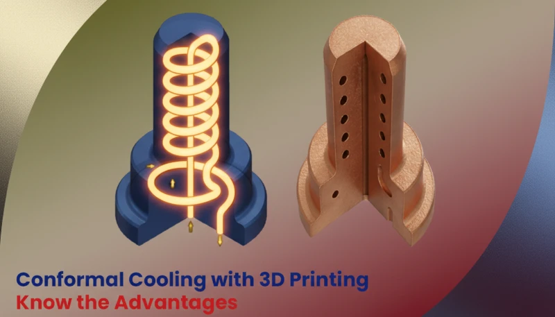
Entre las principales configuraciones de los canales de enfriamiento se incluyen los canales rectos perforados —la opción más sencilla y económica—, los deflectores —que redirigen el flujo hacia orificios ciegos—, los tubos burbujeadores —que crean un flujo anular alrededor de los pernos del núcleo— y los canales de enfriamiento conformales —canales impresos en 3D que siguen el contorno de la cavidad para lograr un enfriamiento uniforme—. El enfriamiento conformal puede reducir el tiempo de ciclo entre un 20 y un 40 % frente a los canales perforados convencionales, aunque incrementa considerablemente el coste del molde.
En algunos casos, el molde necesita calentarse en lugar de enfriarse. Materiales como el policarbonato, el PEEK y ciertos plásticos de ingeniería requieren temperaturas elevadas del molde (80–180 °C) para evitar la solidificación prematura, reducir la tensión residual y alcanzar la cristalinidad adecuada. En estas aplicaciones se utilizan sistemas de canal caliente y calentadores de cartucho.
"La refrigeración representa entre el 50–70% del tiempo total del ciclo de moldeo por inyección en la mayoría de las aplicaciones."True
Verdadero. Después de que la cavidad se llena y compacta, la pieza debe enfriarse lo suficiente para ser expulsada sin deformarse o alabearse. Esta fase de solidificación es típicamente la más larga del ciclo. Optimizar el diseño de los canales de enfriamiento —ubicación, caudal y temperatura— es una de las formas más efectivas de aumentar el rendimiento de producción.
"Todos los moldes de inyección solo necesitan canales de refrigeración; nunca se requiere calentamiento."False
Falso. Muchos termoplásticos de ingeniería como policarbonato, PEEK y nylon requieren temperaturas de molde elevadas para lograr una cristalinidad adecuada y reducir tensiones residuales. En estos casos, el sistema de control de temperatura incluye elementos calefactores como calentadores de cartucho o circulación de aceite caliente junto con o en lugar de agua de enfriamiento.
¿Cómo las piezas estructurales soportan el molde?
Esta sección trata sobre el soporte que aportan las piezas estructurales al molde y su repercusión en el coste, la calidad, los plazos y el riesgo de suministro. Estas piezas constituyen la columna vertebral del molde: mantienen unido el conjunto, garantizan la alineación precisa entre sus mitades y soportan las enormes fuerzas de cierre generadas durante la inyección —normalmente 50–200 toneladas o más, según el tamaño de la máquina—. Los principales componentes estructurales son la base del molde —bastidor estándar—, los pasadores y casquillos guía, los pilares de soporte y las distintas placas.
La base del molde —también llamada bastidor o portamolde— es la estructura exterior que aloja todos los demás componentes. La mayoría de los moldes de inyección utilizan bases normalizadas —como DME, HASCO o LKM— para reducir el tiempo de diseño y fabricación. La base incluye la placa de sujeción superior, la placa A —lado de la cavidad—, la placa B —lado del núcleo—, la placa de soporte, la carcasa del expulsor y la placa de sujeción inferior.
Los pasadores y casquillos guía garantizan que las mitades móvil y fija del molde se alineen con precisión durante el cierre. Un molde estándar utiliza cuatro juegos situados en las esquinas. Para obtener mayor precisión, se añaden enclavamientos cónicos o cierres laterales de cero grados en la superficie de partición. Sin una alineación adecuada, el núcleo y la cavidad pueden desplazarse, lo que provoca rebabas, errores dimensionales y desgaste acelerado.
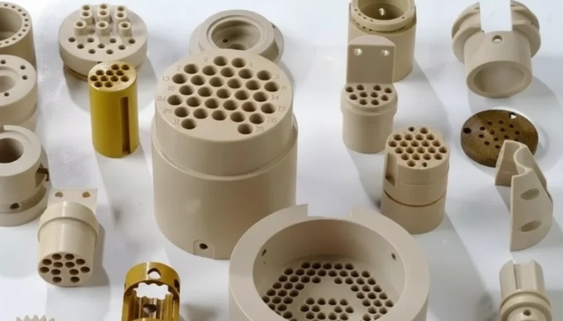
Otros elementos estructurales críticos son los pernos de retorno —que empujan la placa expulsora hacia atrás al cerrarse el molde—, los pilares de soporte —que evitan que la placa B se flexione bajo la presión de inyección— y los bloques de tope —que establecen la altura correcta del molde—. Todos deben dimensionarse y colocarse correctamente para conservar la integridad del molde durante millones de ciclos.
¿Qué hace efectivo al sistema de expulsión?
Después de que la pieza de plástico se ha enfriado y solidificado, debe extraerse del molde — esta es la función del sistema de eyección. El vástago eyector⁴ es el elemento de eyección más común, pero el sistema también incluye placas eyectoras, pines de retorno, muelles, placas desmoldadoras y, en algunos casos, válvulas de aire a presión o extracción robótica.
El diseño del sistema de eyección debe equilibrar varios requisitos en competencia. La fuerza de eyección debe ser lo suficientemente grande para superar la fricción entre el plástico enfriado y la superficie del núcleo, pero no tan grande que dañe la pieza. Los pasadores eyectores deben colocarse en superficies no cosméticas siempre que sea posible, o disfrazados como características funcionales (como refuerzos o intersecciones de nervaduras). El número, diámetro y posición de los pasadores eyectores están determinados por la geometría de la pieza, el comportamiento de contracción del material y los requisitos de acabado superficial.
Para piezas frágiles o de paredes delgadas, se prefieren las placas extractoras a los pernos individuales porque distribuyen uniformemente la fuerza de expulsión por todo el perímetro. Las piezas con núcleos profundos o socavados importantes pueden requerir expulsores tubulares o expulsores inclinados. En todos los casos, el sistema de expulsión debe funcionar con fluidez a la velocidad de producción: cualquier atasco o expulsión irregular provoca paradas y rechazos.
Nuestro rango de máquinas de 90T a 1850T significa que producimos desde pequeños componentes médicos de precisión hasta piezas estructurales grandes. Cada categoría de pieza requiere una estrategia de eyección diferente. Trabajar bajo sistemas ISO 9001 e ISO 13485 garantiza que nuestros diseños de eyección sean validados antes de que comience la producción.
¿Cómo los sistemas de guía y escape aseguran la calidad?
Hay dos sistemas fáciles de pasar por alto, pero fundamentales para la calidad: el sistema de guiado y el sistema de ventilación. El primero garantiza que las mitades móvil y fija del molde se alineen con precisión en cada ciclo. El segundo evacua el aire y los gases atrapados en la cavidad durante el llenado; sin él aparecen quemaduras, llenados incompletos y líneas de soldadura débiles.
El sistema de guía utiliza pasadores guía (pasadores líderes) y bujes guía montados en las cuatro esquinas del molde. Estos se acoplan primero cuando el molde se cierra, alineando aproximadamente las dos mitades antes de que el núcleo y la cavidad hagan contacto. Para moldes de mayor precisión, se agregan elementos de localización adicionales como enclavamientos cónicos, cerraduras de lados rectos o bloques de localización cónicos en la superficie de partición para mantener la alineación dentro de más o menos 0.01 mm.
El sistema de escape funciona mediante ranuras poco profundas (0.03–0.20 mm de profundidad, 1.5–6 mm de ancho) mecanizadas en la superficie de partición, típicamente al final de la trayectoria de flujo del fundido. Estas ranuras permiten que el aire atrapado y los gases de descomposición escapen. Si el escape es insuficiente, el gas comprimido se calienta rápidamente (compresión adiabática) y puede alcanzar temperaturas que queman o decoloran la superficie del plástico — un defecto conocido como efecto diésel o quemadura por gas.
Además de las ranuras de ventilación dedicadas, los diseñadores de moldes utilizan vías de escape secundarias: el espacio entre los pasadores eyectores y sus agujeros, entre los deslizadores y sus guías, y entre los levantadores y el núcleo. Estas ventilaciones incidentales complementan las ranuras de ventilación primarias, especialmente para piezas complejas con múltiples frentes de flujo y líneas de unión.
Preguntas frecuentes
¿Cuáles son los seis sistemas funcionales principales de un molde de inyección?
Los seis sistemas principales son el sistema de alimentación (suministra plástico fundido), las piezas de moldeo (definen la geometría de la pieza), el sistema de control de temperatura (regula el enfriamiento y calentamiento), las piezas estructurales (soportan y alinean el molde), el sistema de expulsión (remueve la pieza terminada) y el sistema de escape (ventila el aire y gases atrapados). Cada sistema debe trabajar en coordinación para una producción confiable y de alta calidad. Una falla en cualquier sistema — como un escape bloqueado, una compuerta de tamaño insuficiente o un pasador guía desalineado — puede generar una cascada de defectos, tiempo de inactividad y costosas retrabajos. Comprender cómo interactúan estos sistemas es esencial para especificar, revisar o solucionar problemas en los moldes de inyección.
¿Cómo afecta el sistema de alimentación a la calidad de la pieza moldeada por inyección?
El sistema de compuertas controla cómo el plástico fundido entra en la cavidad. El tamaño, tipo y ubicación de la compuerta influyen directamente en el patrón de llenado, la distribución de presión, la posición de la línea de soldadura y la apariencia superficial. Una compuerta mal diseñada puede causar chorreo, hundimientos, líneas de flujo o llenado incompleto. Por ejemplo, una compuerta demasiado pequeña aumenta el esfuerzo cortante y puede degradar el polímero, mientras que una compuerta en la ubicación incorrecta puede atrapar aire y causar quemaduras por gas. Esto hace que el diseño de compuertas sea una de las decisiones más críticas en la ingeniería de moldes, a menudo validada mediante simulación de flujo de molde antes de cortar el acero.
¿Cuál es la diferencia entre un núcleo y una cavidad en un molde?
La cavidad (molde hembra o matriz) forma la forma externa y las superficies cosméticas de la pieza. El núcleo (molde macho o punzón) forma las características internas como agujeros, nervaduras y bolsillos. Juntos, el núcleo y la cavidad definen la geometría 3D completa de la pieza moldeada cuando el molde está cerrado. La cavidad generalmente se monta en el lado fijo del molde, mientras que el núcleo está en el lado móvil donde ocurre la eyección. Ambos deben mecanizarse con tolerancias extremadamente ajustadas —a menudo dentro de ±0.01 mm— para garantizar la precisión de la pieza y evitar rebabas en la línea de partición.
¿Por qué es tan importante el diseño de los canales de enfriamiento en los moldes de inyección?
El enfriamiento típicamente representa el 50–70% del tiempo total del ciclo, convirtiéndolo en el factor individual más grande en la eficiencia de producción. Un diseño eficiente de los canales de enfriamiento reduce el tiempo del ciclo, mejora el rendimiento y previene defectos como alabeo y contracción desigual. Enfoques avanzados como el enfriamiento conformado — donde los canales siguen el contorno de la cavidad — pueden reducir el tiempo del ciclo en un 20–40% en comparación con los canales rectos perforados convencionales. Un diseño deficiente de enfriamiento no solo ralentiza la producción, sino que también crea dimensiones de pieza y calidad superficial inconsistentes, por lo que la simulación térmica es una práctica estándar en el diseño profesional de moldes.
¿Qué sucede si el sistema de escape en un molde es insuficiente?
Un escape insuficiente hace que el aire y los gases atrapados se compriman adiabáticamente, generando temperaturas locales extremas que pueden quemar o decolorar la superficie plástica —un defecto conocido como efecto diésel o quemadura por gas. También conduce a llenados incompletos, líneas de unión débiles donde se encuentran múltiples frentes de flujo y huecos internos. Las ranuras de ventilación adecuadas (0.03–0.20 mm de profundidad) mecanizadas al final de las rutas de flujo, combinadas con los espacios libres de los pasadores eyectores que actúan como escapes secundarios, previenen estos problemas. En moldes de múltiples cavidades, un escape equilibrado en todas las cavidades es crítico para una calidad de pieza consistente.
¿De qué materiales están hechos los núcleos y cavidades de los moldes de inyección?
La mayoría de los moldes de producción utilizan aceros para herramientas endurecidos como P20, H13, S136 o 718H, tratados térmicamente a 48–54 HRC para durabilidad y resistencia al desgaste. P20 es la opción más común para moldes de propósito general, mientras que H13 y S136 son preferidos para materiales de alta temperatura o corrosivos. Para aplicaciones de alto volumen o abrasivas, las superficies del molde pueden recibir recubrimientos adicionales como TiN (nitruro de titanio) o cromado. Los moldes para prototipos y series cortas a veces usan aluminio (Al 7075) para un mecanizado más rápido y menor costo, aunque los moldes de aluminio tienen una vida útil significativamente más corta.
¿Cuántos pasadores eyectores necesita un molde de inyección típico?
El número de pasadores eyectores depende de la geometría de la pieza, tamaño, espesor de pared y comportamiento de contracción del material. Una pieza pequeña y simple puede necesitar solo 4–8 pasadores, mientras que una pieza compleja con paredes delgadas, profundos dibujos o características delicadas puede requerir 20–50 o más. El principio clave es distribuir la fuerza de eyección uniformemente a través de la pieza para prevenir deformación, agrietamiento o adherencia durante el desmoldeo. Para piezas frágiles, se pueden usar placas desmoldadoras o eyectores de manguito en lugar de pasadores individuales para proporcionar una fuerza de eyección uniforme a lo largo de todo el perímetro de la pieza.
¿Pueden los moldes de inyección tener sistemas de calentamiento y enfriamiento?
Sí, muchos moldes de inyección incorporan capacidades de calentamiento y enfriamiento. Los termoplásticos de ingeniería como policarbonato, PEEK y nailon requieren temperaturas de molde elevadas (80–180°C) durante el llenado para evitar la congelación prematura y lograr una cristalinidad adecuada. Estos moldes utilizan calentadores de cartucho o circulación de aceite caliente junto con canales de agua de enfriamiento. Durante las fases de llenado y empaquetado, el calentamiento mantiene la temperatura del molde; durante la fase de enfriamiento, el sistema puede cambiar a enfriamiento activo para acelerar la solidificación. Este control de temperatura de doble modo es una práctica estándar en el moldeo de precisión de plásticos de ingeniería de alto rendimiento.
¿Necesita un molde de inyección de precisión bien diseñado y fabricado a la primera? Nuestro equipo de ingeniería en Shanghái cuenta con más de 20 años de experiencia en el diseño de moldes con sistemas optimizados de alimentación, enfriamiento y expulsión para más de 400 materiales. Póngase en contacto con nosotros para hablar de su próximo proyecto de molde; responderemos en un plazo de 24 horas con una cotización técnica detallada. Para obtener una visión más amplia del utillaje, consulte nuestra guía completa sobre moldes de inyección.
Molde de inyección: herramienta de precisión utilizada en fabricación para dar al plástico fundido la forma deseada mediante la inyección del material a alta presión en una cavidad. ↩
Sistema de alimentación: red de canales de un molde que guía el plástico fundido desde la boquilla de la máquina hasta la cavidad, incluidos el bebedero, los canales y las entradas. ↩
Ángulo de desmoldeo: ligera inclinación aplicada a las superficies verticales de la cavidad de un molde para facilitar la extracción de la pieza moldeada durante la expulsión. ↩