 콘텐츠로 건너뛰기

- 냉각은 얇은 벽 성형에서도 사이클 시간 측면에서 지배적인 단계입니다. 벽 두께가 얇기 때문에 열 확산이 빠르며, 일반적으로 2~4초의 냉각으로 이젝션 온도에 도달하기에 충분합니다. 직선 드릴 채널이 아닌 캐비티 윤곽을 따라가는 컨포멀 냉각 채널은 부품 전체의 온도 변화를 40~60% 줄이고 사이클을 20~30% 더 빠르게 합니다. 0.6mm PP 용기의 경우, 잘 설계된 컨포멀 냉각은 2초 이내에 이젝션 준비가 된 부품을 제공합니다.
- Cycle times of 2–5 seconds are achievable — 5 to 10 times faster than conventional molding — making this process cost-effective for high-volume packaging and electronics.
- Material selection is critical: polypropylene (PP) with MFI of 40–60 g/10 min and ABS or PA66+GF high-flow grades dominate thin-wall applications.
- Tool steel grade (P20 for prototypes, H13 for production runs over 500,000 cycles) and conformal cooling channels directly determine part quality and tool life.
- ZetarMold runs 47 injection molding machines, including dedicated high-speed presses for thin-wall work, supporting customers from DFM review through mass production.
What Is Thin Wall Injection Molding?
박벽 사출 성형1 는 사출 속도 500~1,500 mm/s에서 벽 두께가 1mm 미만인 부품을 위한 제조 공정입니다. 본 문서는 벽 두께가 1mm 미만으로 떨어질 때 성패를 결정하는 매개변수, 재료, 금형, 결함 방지 전략을 다룹니다.
더 넓은 관점을 위해 우리의 injection molding complete guide 프로세스 기본 원리, 재료 행동 및 생산 결정을 포함합니다.
For broader context, compare this topic with 사출 성형, 사출 금형2및 supplier sourcing guide.
박벽 사출 성형은 벽 두께가 1.0mm 미만 — 대량 포장 및 소비자 가전에서는 종종 0.4mm까지 얇은 — 플라스틱 부품을 생산하는 특수 제조 공정입니다. 일반 성형과 달리, 박벽 작업은 얇은 재료가 금형 내에서 얼기 전에 완전한 캐비티 충전을 달성하기 위해 더 높은 사출 속도, 높은 팩 압력, 정밀 금형을 요구합니다. 설계 마진이 매우 좁으며, 용융 온도부터 게이트 위치까지 모든 매개변수가 일관된 부품 품질3.

| Metric | Thin-Wall | Conventional | Why It Matters |
|---|---|---|---|
| 벽 두께 | <1.0 mm | 1.5–4.0 mm | Drives fill speed requirement |
| L/T ratio | >150:1 | <100:1 | Primary classification criterion |
| 사출 속도 | 500–1,500 mm/s | 50–200 mm/s | Must outrun freeze-off |
| Clamp force | 0.5–0.8 톤/cm² | 0.3–0.5 톤/cm² | Resists flash at high pressure |
In our factory at ZetarMold, we typically classify a part as thin-wall when any section falls below 0.8 mm or when the L/T ratio exceeds 200:1. At that threshold, conventional machines simply cannot fill the cavity — the material freezes off mid-flow and you get a short shot every time. The practical wall range for most consumer packaging is 0.5–0.9 mm; electronics and medical parts can push down to 0.3 mm with the right tool geometry.
The process is not just “regular injection molding with thinner walls.” It requires dedicated equipment with accumulators, a completely different gating strategy, tighter temperature control, and — critically — a mold design that accommodates the higher clamping force needed to resist flash at elevated pressures. Every element of the system must be engineered together.
How Does Thin Wall Injection Molding Work?
박벽 성형은 일반 사출 성형과 유사하지만 극한의 매개변수로 운전되어 캐비티 충전을 150밀리초 미만으로 완료합니다. 사출 단계는 박벽 작업이 일반 작업과 가장 크게 차별화되는 부분으로, 급속 충전과 정밀한 열 제어를 중심으로 구축된 완전히 다른 사출기 사양과 금형 전략을 요구합니다.
Injection speed must reach 500–1,500 mm/s to fill the cavity before the melt front drops below the material’s no-flow temperature. For reference, conventional molding typically runs at 50–200 mm/s. The higher speed compresses the melt and generates significant shear heat, which helps offset the rapid heat loss to the cold mold wall. Timing is measured in milliseconds: a 0.5 mm wall part may fill in 0.05–0.10 seconds. On our high-speed presses, we monitor injection time in real time to detect any drift that might indicate a blocked vent or a gate that is beginning to wear.
| Phase | Thin-Wall Molding | Conventional Molding |
|---|---|---|
| Fill time | 0.05–0.15 s | 1–5 s |
| Hold time | 0.5–1.5 s | 3–10 s |
| 냉각 시간 | 2–4 s | 10–45 s |
| Total cycle | 2–5 s | 15–60 s |
Pack and hold pressure is applied immediately after fill to compensate for volumetric shrinkage as the part solidifies. In thin-wall work, the hold phase is short — typically 0.5–1.5 seconds — because the wall freezes rapidly and additional hold time does not improve density. Over-packing is a common mistake that causes flash and sticking. In our factory, we monitor the hold-to-fill transition using in-cavity pressure sensors, cutting hold the moment pressure stabilizes — usually within 0.8 seconds of fill completion.
Cooling is the dominant phase in terms of cycle time even in thin-wall molding. Because wall thickness is small, thermal diffusion is fast — 2–4 seconds of cooling is typically sufficient to reach ejection temperature. Conformal cooling channels that follow the cavity contour, rather than straight-drilled channels, reduce temperature variation across the part by 40–60% and allow 20–30% faster cycles. For a 0.6 mm PP container, well-designed conformal cooling delivers ejection-ready parts in under 2 seconds.
전자 장치 하우징, 장난감True
In thin-wall parts, the melt front must reach all extremities of the cavity before the plastic solidifies. Raising injection speed from 200 mm/s to 800 mm/s reduces fill time by 75%, keeping the melt above the no-flow temperature throughout and eliminating the root cause of short shots in thin sections.
“You can use any standard injection machine for thin-wall parts.”False
Standard machines lack the accumulator-assisted injection unit needed to achieve 500–1,500 mm/s injection speeds, and their clamping systems are not designed for the high cavity pressures (140–250 MPa) required for thin walls. Using a conventional machine results in short shots, excessive flash, or machine damage.
What Are the Key Processing Parameters for Thin Wall Molding?
Thin-wall processing operates in narrow windows: any deviation from the optimal range immediately produces defects. The following parameters are the primary levers our process engineers adjust during qualification. A 5°C drop in melt temperature, a 10 MPa reduction in injection pressure, or a 2-second delay in cooling time can shift a part from acceptable to 100% scrap — tolerances that would be inconsequential in conventional 2 mm wall molding.
| 매개변수 | Thin-Wall Range | Conventional Range | Effect of Deviation |
|---|---|---|---|
| 사출 속도 | 500–1,500 mm/s | 50–200 mm/s | Too low → short shot; too high → flash or jetting |
| 사출 압력 | 140–250 MPa | 70–140 MPa | Too low → short shot; too high → flash, excessive clamp |
| 용융 온도 | 220–280°C (PP) | 200–260°C | Too high → degradation; too low → freeze-off |
| 금형 온도 | 15–30°C (PP) | 20–60°C | Too high → cycle time increase; too low → warpage |
| 주기 시간 | 2–5 s | 15–60 s | Too short → part not fully solid at ejection |
| Clamp force | 0.5–0.8 톤/cm² | 0.3–0.5 톤/cm² | Insufficient → flash at parting line |
Melt temperature control is especially critical because thin-wall sections cool 3–5 times faster than conventional parts. If melt temperature is 10°C below the recommended range, the outer skin freezes before the melt front reaches the last-fill zone, producing a short shot even at maximum injection speed. We set the barrel temperature profile so the nozzle zone is 5–10°C above the rear zone, maintaining consistent melt temperature at the gate and reducing fill inconsistency between shots.

박벽 금형의 클램프력 계산은 높아진 캐비티 압력을 고려해야 합니다. 투영 면적 × 0.3–0.5 톤/cm²라는 표준 추정치는 불충분합니다 — 박벽 작업에는 0.5–0.8 톤/cm²를 사용하세요. 클램프력이 부족한 금형은 사출 매개변수가 정확해도 파팅 라인에서 플래시가 발생하며, 플래시를 멈추기 위해 단순히 사출 압력을 낮추면 부품은 숏 샷 상태로 빠집니다.
| 매개변수 | Thin-Wall Requirement | Conventional Baseline | Key Rule |
|---|---|---|---|
| Clamp force | 0.5–0.8 톤/cm² | 0.3–0.5 톤/cm² | Calculate from projected area × 0.65 as starting point |
| Gate thickness | Match wall (0.6–0.8 mm) | 0.5–1.5 mm | Never smaller than wall thickness |
| Gate position | Thickest section | Anywhere balanced | Flow toward thin areas, not away |
| Vent depth | 0.015–0.025 mm | 0.02–0.04 mm | At last-fill points to prevent diesel effect |
Gate sizing is particularly critical in thin-wall tools. A gate that is too small restricts flow and elevates pressure drop; a gate that is too large causes jetting or weld-line defects. For walls under 0.8 mm, gate thickness should match or slightly exceed wall thickness — typically 0.6–0.8 mm — placed at the thickest section of the part to allow the melt front to progress toward thinner sections without premature freeze.
Venting is often underestimated. At 1,500 mm/s, trapped air in the cavity compresses faster than it can escape through normal parting line clearances. Dedicated vent slots (0.015–0.025 mm deep, 3–5 mm wide) at the last fill point prevent burn marks, short shots from air traps, and diesel effect — a flash-like defect caused by adiabatic compression igniting the resin.
Which Materials Work Best for Thin Wall Injection Molding?
Material selection for thin-wall parts is dominated by flow behavior. Resins must have a melt flow index high enough to fill the cavity before freeze-off, yet enough mechanical integrity after solidification to survive ejection without cracking. Standard resins used in conventional molding are frequently too viscous for thin-wall work.
폴리프로필렌(PP)은 주요 박벽 수지로, 전체 박벽 포장 생산의 약 60%를 차지합니다. 이상적인 등급은 MFI가 40–60 g/10분(230°C/2.16 kg 측정)입니다. 높은 MFI 등급은 0.5mm 단면으로 쉽게 흐르지만 내충격성이 떨어질 수 있습니다; 제조사는 이를 핵형제와 내충격 개질제로 균형을 맞춥니다. PP의 낮은 밀도(0.90–0.91 g/cm³)는 부품 무게를 줄여 포장 경제성의 핵심 동인이 됩니다.
For structural and electronics applications, ABS high-flow grades (MFI 15–25 g/10 min at 220°C/10 kg) and PA66 reinforced with 15–30% glass fiber are preferred. The glass fiber increases stiffness significantly — from ~2.5 GPa for unfilled PA66 to 6–8 GPa for PA66+30%GF — allowing thinner walls while maintaining the structural performance required for connector housings, brackets, and enclosure panels.
| 재료 | MFI (g/10 min) | Min Wall (mm) | Best Applications | Key Limitation |
|---|---|---|---|---|
| PP (high-flow) | 40–60 | 0.4 | Packaging, caps, containers | Lower stiffness than engineering resins |
| ABS (high-flow) | 15–25 | 0.6 | Electronics housings, toys | 필름 게이트 또는 팬 게이트 사용; 게이트 직경 증가; 게이트에서 사출 속도 감소 |
| PA66+GF15% | 10–20 | 0.5 | Connector housings, brackets | Moisture absorption, higher cost |
| HDPE (high-flow) | 20–40 | 0.5 | Caps, food-grade packaging | Low stiffness, prone to warpage |
| LDPE / LLDPE | 15–30 | 0.4 | Flexible lids, closures | Not suitable for rigid structures |
One material decision point that surprises many buyers: using the same resin grade as in your conventional tools will likely not work in a thin-wall tool. We frequently see customers bring a PP grade with MFI 12 g/10 min that runs perfectly in a 2 mm wall part but causes 100% short shots in a 0.7 mm wall tool. Resin qualification is a mandatory step, not an afterthought — budget one to two weeks for material trials before tool sign-off.
How Should You Design a Mold for Thin Wall Parts?
박벽 금형은 게이트 형상, 컨포멀 쿨링, 배기, 이젝션 전략, 강재 선택이라는 다섯 가지 핵심 설계 영역으로 정의됩니다. 이 중 하나라도 잘못되면 불량품, 파손된 금형, 또는 허용할 수 없을 정도로 긴 사이클 타임이 발생합니다.
Gate design drives fill balance and weld line location. For rectangular thin-wall parts like food containers, a film gate running along the full width of one edge gives the most uniform fill front and eliminates weld lines entirely. Fan gates work well for smaller parts. Point gates (hot or cold) at the thickest feature — typically a boss or rib — direct the melt toward thinner areas, but require careful simulation to avoid weld lines at visible surfaces.
| 볼륨 | Recommended Steel | 경도 | Cost vs. P20 |
|---|---|---|---|
| <50,000 shots | Aluminum (QC-10) | N/A | 30–50% less |
| 100,000–500,000 shots | P20 pre-hardened | 30–36 HRC | Baseline |
| >1,000,000 shots | H13 hot-work tool steel | 48–52 HRC | 15–25% more |
| >5,000,000 shots | H13 + PVD coating | 58–62 HRC surface | 25–40% more |
Steel selection is determined by production volume. For prototype runs under 50,000 shots, aluminum (Alcoa QC-10 or equivalent) machines faster and costs 30–50% less than steel tooling. For production volumes of 100,000–500,000 shots, P20 pre-hardened steel (30–36 HRC) is the workhorse choice. For high-volume runs exceeding 1,000,000 shots — typical in packaging — H13 hot-work tool steel hardened to 48–52 HRC is required. H13 resists the higher contact stress from elevated cavity pressures and maintains dimensional accuracy over millions of cycles.
“Conformal cooling channels are worth the added mold cost for thin-wall production.”True
Conformal cooling channels follow the cavity contour, reducing temperature variation from ±15°C to ±5°C and enabling 20–30% faster cycles. At 10 million shots per year on a packaging line, a 20% cycle time reduction translates to 2 million additional parts annually — easily justifying the 15–25% higher mold cost.
“Standard mold steel P20 is sufficient for all thin-wall production volumes.”False
P20 (30–36 HRC) is adequate for prototype and medium-volume work up to approximately 500,000 shots. Above that threshold, the elevated cavity pressures in thin-wall molding (up to 250 MPa) cause accelerated wear and dimensional drift. H13 at 48–52 HRC is required for high-volume production to maintain gate and cavity dimensions through millions of cycles.
What Are the Common Defects in Thin Wall Injection Molding and How to Prevent Them?
Thin-wall parts are highly sensitive to process variation. The same root cause that produces a barely acceptable part at nominal conditions creates a 100% defect rate when one parameter drifts by 10%. Understanding the specific failure modes allows engineers to set tight process alarm limits and prevent downtime. In our quality system at ZetarMold, all thin-wall tools are fitted with cavity pressure sensors that trigger automatic part rejection when peak pressure deviates more than ±5% from the nominal value — catching short shots and flash before they reach the quality inspection stage.
The following table summarizes the seven most common defects we encounter on thin-wall tools, along with their root causes and the corrective actions that reliably fix them. Note that several defects share symptoms but require opposite interventions — correctly identifying the root cause before adjusting parameters saves significant troubleshooting time.
| 결함 | Root Cause | Prevention |
|---|---|---|
| 쇼트 샷 | Insufficient speed/pressure; freeze-off before fill complete | Increase injection speed; optimize gate size; increase melt temp |
| 플래시 | Excessive injection pressure; insufficient clamp force; worn parting line | Reduce pack pressure; verify clamp tonnage; inspect parting line |
| 뒤틀림 | Non-uniform cooling; unbalanced flow; residual stress | Conformal cooling; balanced runner; symmetrical gate placement |
| 금형 수명 종료: | Insufficient pack pressure; premature gate freeze | Increase hold pressure/time; enlarge gate; raise mold temperature |
| 용접 라인 | Multiple flow fronts meeting without sufficient heat | Relocate gate; increase melt temperature; reduce wall variation |
| Burn marks | Trapped air; excessive injection speed in end-fill zone | Add venting at last-fill locations; reduce speed in final 5–10% of fill |
| 제트기 | Gate too small; high injection speed with poor gate design | Use film or fan gate; increase gate diameter; reduce injection speed at gate |
사출 성형으로 달성 가능한 최소 벽 두께는 얼마인가요?True
Several thin-wall defects share visible symptoms but require opposite corrective actions. Weld lines and sink marks can both appear as surface depressions — increasing pack pressure addresses a sink mark but does nothing for a weld line’s root cause (gate location and melt temperature). Similarly, flash and short shots are caused by opposite conditions: excess pressure vs. insufficient pressure. Misdiagnosing the defect and adjusting in the wrong direction typically makes the problem worse, wastes machine time, and can damage tooling.
“The same process settings can be used for thin-wall injection molding across packaging, electronics, and medical applications.”False
Each application segment requires fundamentally different process parameters and quality requirements. Packaging optimizes for maximum throughput and minimum material cost (simple QC, FDA resin compliance). Electronics demands Class A surface quality with tight dimensional tolerances (±0.1 mm). Medical applications require IQ/OQ/PQ process validation, clean-room production, and biocompatible resins (USP Class VI). Automotive parts need PPAP qualification and IATF 16949 controls. A single process window does not serve all these segments — material selection, validation protocols, and QC rigor differ substantially.
In our production experience at ZetarMold, the most frequently misdiagnosed thin-wall defect is a weld line mistaken for a sink mark. A weld line appears as a visible seam on the surface, often with a slight depression. Operators sometimes increase pack pressure, which fixes the depth but not the seam visibility. The real fix is to reposition the gate so both flow fronts merge at a non-visible surface, or to run a mold flow analysis simulation before the tool is cut to predict and eliminate weld line locations during the design phase rather than after production has started.
Controlling Flash in Thin-Wall Tools
플래시 방지는 체계적인 접근이 필요합니다. 사출 매개변수 조정 외에도, 클램프 토너지가 올바르게 계산되었는지 확인해야 합니다 — 박벽 부품의 경우, 기존의 0.3–0.5 톤/cm² 대신 캐비티의 투영 면적에 0.5–0.8 톤/cm²를 곱한 값을 사용하세요. 클램프력이 부족한 박벽 금형은 낮은 팩 압력에서도 플래시가 발생하며, 제대로 채우기 위해 압력을 높이면 플래시는 더 악화됩니다. 금형이 낮은 팩 압력에서도 지속적으로 플래시가 난다면, 다른 매개변수를 조정하기 전에 먼저 클램프력 계산을 확인하세요. 플레튼에 장착된 디지털 클램프력 지시기는 실시간 피드백을 제공하여 대부분의 플래시 결함을 유발하는 추측 작업을 피하는 데 도움이 됩니다.
Where Is Thin Wall Injection Molding Used?
박벽 사출 성형은 식품 포장, 전자제품, 의료, 자동차, 클로저 분야의 경량 부품을 위한 주요 공정입니다. 각 분야는 별도의 벽 두께 요구사항, 재료 사양, 품질 기준 및 생산 규모 요구사항을 가지고 있으며, 이는 금형 설계 및 공정 제어 전략.
| 산업 | Typical Wall (mm) | Key Material | Volume/Year |
|---|---|---|---|
| Food & beverage packaging | 0.5–0.8 | PP (FDA grade) | Billions of units |
| 가전 제품 | 0.8–1.2 | ABS / PC-ABS | Hundreds of millions |
| Medical disposables | 0.3–0.7 | PP / PE (USP VI) | Billions of units |
| Automotive interior | 1.0–1.5 | PA+GF / PBT | Tens of millions |
| Industrial caps & closures | 0.6–1.0 | PP / HDPE | Billions of units |
Market-Specific Requirements at a Glance
Food and beverage packaging accounts for the largest volume by far. PP thin-wall containers for yogurt, deli items, and ready meals are produced at very high rates of 10,000–50,000 cycles per day per cavity. Wall thickness is typically 0.5–0.8 mm. FDA-compliant PP grades meeting 21 CFR requirements are standard; no heavy metal stabilizers, no BPA. The economics are compelling: a 0.6 mm wall container uses 25–30% less material than a 0.9 mm wall equivalent.
Consumer electronics enclosures represent the second-largest thin-wall segment. Smartphone housings, laptop palms, and tablet backs require walls of 0.8–1.2 mm in ABS or PC/ABS blends to achieve Class A surface quality with embedded snap features and living hinges. Dimensional tolerances are tight — typically ±0.1 mm — and surface finish must be free of flow marks, which demands careful gate placement and mold flow simulation before tooling. Post-mold operations including pad printing, ultrasonic welding, and surface coating require part-to-part consistency that thin-wall processes deliver when properly validated.
| Segment | Key Standard | Critical Requirement |
|---|---|---|
| 식품 포장 | FDA 21 CFR | Resin compliance, no BPA |
| 의료 기기 | USP 클래스 VI / ISO 10993 | Biocompatibility, process validation |
| 자동차 | IATF 16949 | PPAP, Cpk ≥1.67 |
| 전자 제품 | RoHS / REACH | Halogen-free materials |
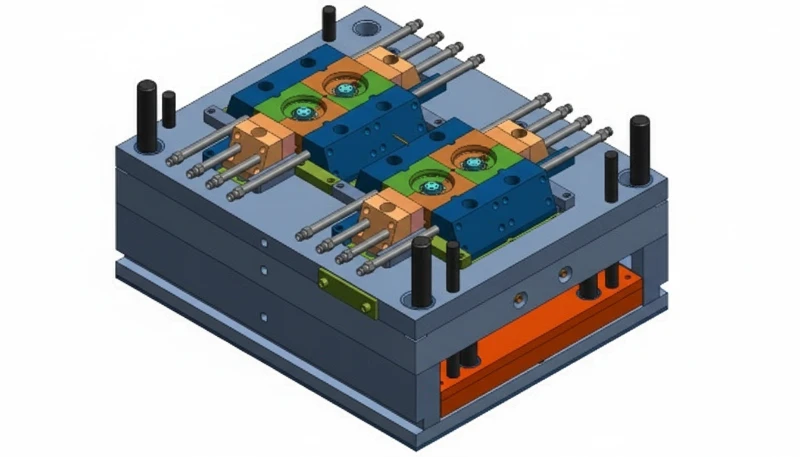
At our Shanghai factory, we run 47 injection molding machines from 90T to 1850T, including dedicated high-speed presses for thin-wall production. With experience across 400+ plastic materials, we support customers from DFM review through mass production of thin-wall parts — from 0.3 mm medical disposables to high-volume PP packaging running at 15,000 shots per hour.
Medical disposables — syringe barrels, pipette tips, diagnostic cartridges, and microfluidic chips — require both thin walls (0.3–0.7 mm) and biocompatible materials (USP Class VI certified resins). Clean-room production and validated processes (IQ/OQ/PQ qualification protocols) add cost but are non-negotiable for regulated markets. Automotive interior parts (clip housings, connector brackets, door panel inserts) complete the picture, demanding PA or PBT with high glass fiber content for the structural rigidity required in underhood and cabin environments up to 140°C.
Frequently Asked Questions About Thin Wall Injection Molding?
자주 묻는 질문
What wall thickness qualifies as ‘thin wall’ in injection molding?
A part is classified as thin-wall when any cross-section is below 1.0 mm with a flow-length-to-thickness (L/T) ratio above 150:1. In practice, most packaging applications fall in the 0.5–0.8 mm range. Parts with walls of 1.0–1.5 mm and high L/T ratios (150:1–200:1) occupy a transitional zone that requires some thin-wall process adjustments but not necessarily dedicated thin-wall equipment. The L/T ratio is the more reliable classification criterion: a long, slender 1.2 mm section can behave like a true thin-wall part during fill.
How fast is thin wall injection molding compared to standard molding?
Cycle times for thin-wall parts are typically 2–5 seconds, compared to 15–60 seconds for conventional injection molding — a 5–10× speed advantage. This is driven by rapid heat dissipation from thin cross-sections, which cuts cooling time dramatically. At ZetarMold, high-volume thin-wall packaging runs at 12,000–15,000 shots per hour on multi-cavity tools, producing over 100,000 finished parts per hour on a 16-cavity tool. On an annual basis, this speed advantage translates directly to lower per-part cost and faster response to demand spikes.
What injection pressure is required for thin wall parts?
Thin-wall injection molding requires injection pressure of 140–250 MPa, compared to 70–140 MPa for conventional molding. The elevated pressure is necessary to drive high-flow-rate melt into very thin cavities before freeze-off occurs. Machines must be equipped with accumulators or servo-driven injection units to achieve the rapid pressure buildup required — conventional hydraulic machines cannot respond fast enough. Cavity pressure sensors are strongly recommended to monitor and control the actual pressure inside the mold, not just the hydraulic pressure at the machine.
Can I use my existing injection molding machine for thin wall parts?
Usually not without significant upgrades. Standard machines lack the accumulator-assisted injection unit needed to achieve 500–1,500 mm/s injection speeds. The injection unit response time on a conventional machine is too slow — by the time full pressure builds, the thin section has already started to freeze. Dedicated thin-wall presses from Husky, Netstal, or Engel with servo-electric or accumulator-hydraulic systems are required for consistent production. Some processors retrofit an accumulator to an existing machine, which can work if the injection speed and response time are verified post-retrofit.
What is the minimum wall thickness achievable with injection molding?
생산 사출 성형에서 달성 가능한 최소 벽 두께는 정밀 금형과 국부 가열을 사용한 고유동 PP 또는 LCP 수지로 약 0.3mm입니다. 0.5–0.6mm 벽 두께는 다양한 재료에서 더 일상적으로 달성 가능합니다. 최소 벽 두께를 제한하는 요인으로는 충전 온도에서의 재료 점도, 게이트부터 최종 충전 지점까지의 거리(흐름 길이), 금형 온도 균일성, 사용 가능한 사출 압력이 있습니다. 0.3mm 미만에서는 치수 일관성을 유지하기 위해 특수 장비 — 1 cm³ 미만의 배럴 용적, 정밀 스크류 — 를 사용한 마이크로 사출 성형이 필요합니다.
Does thin wall injection molding require special mold steel?
Yes. For prototype and low-volume work under 50,000 shots, aluminum tooling (Alcoa QC-10 or equivalent) is cost-effective and machines faster. For medium production runs of 100,000–500,000 shots, P20 pre-hardened steel (30–36 HRC) is the standard choice. For high-volume production above 1,000,000 shots — typical in packaging — H13 hot-work tool steel hardened to 48–52 HRC is required to resist the higher cavity pressures up to 250 MPa and maintain dimensional accuracy over millions of cycles without gate wear or cavity distortion.


