 コンテンツへスキップ

初めての量産サンプルが戻ってきましたが、パーツが金型に張り付いています。エジェクターピンが跡を残しています。側面に引きずり傷が入っているパーツさえあります。金型メーカーはドラフトを増やす必要があると言います。CADがきれいに見えたのでドラフトゼロを要求しました。今、$12,000の金型が手直しを必要としています。良いニュース:金型製作開始前にドラフト角を理解していれば、これは最も簡単に防げる問題の一つです。
この記事では、 抜き勾配1 とは何か、なぜ重要なのか、材料とテクスチャーによる標準値、そして実際の量産で実害を出した私が見てきた失敗について説明します。
- 標準的な抜き勾配は、ほとんどの研磨面で片側1~2度である。
- テクスチャー加工された表面は、テクスチャーグレードごとに1〜1.5度の追加抜き勾配が必要です。
- ゼロ抜き勾配は可能だがリスクが高く、生産ではほとんど価値がない。
- 抜き勾配は工具加工開始前に適用する必要がある — 再加工は高価である。
- 収縮、材料、肉厚はすべて必要な最小抜き勾配に影響する。
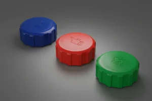
マイクロ成形部品のクローズアップ
A 射出成形 抜き勾配は、金型キャビティのすべての垂直面に意図的に設けられたテーパーです。部品が冷却・収縮してコアに密着した後、自由にスライドして取り出せるように壁に加えるわずかな傾きと考えてください。これがないと、部品は真空シールのように鋼に密着し、エジェクションピンと金型表面の間で押し出しが困難になります。
抜き勾配は金型開き方向の垂直軸からの角度で測定されます。1度の抜き勾配は、深さ1mmあたり約0.0175mm外側に傾くことを意味します。深さ50mmのポケットでは、上部で側面あたり約0.87mmのクリアランスが得られます。小さく聞こえますが、きれいなエジェクションと部品の詰まりの違いを生みます。
パーツのすべての垂直面にはドラフトが必要です。これには外壁、内部リブ、ボス、ポケット、さらにはスルーホールも含まれます。表面が金型開き方向に対して平行でテーパーがない場合、パーツはエジェクション時に引きずられ、傷、スコアリング、または反りが生じます。
なぜ抜き勾配は部品品質にとって重要なのか?
このセクションでは、ドラフト角がパーツ品質にどのように影響し、コスト、品質、納期、調達リスクにどのような影響を与えるかについて説明します。ドラフト角は、パーツの外観、寸法精度、工具寿命、サイクルタイムの4つに直接影響します。パーツが金型に張り付くと、 射出成形金型 排出システム2 もっと努力しなければならない。エジェクターピンは痕跡を残す。部品表面には引きずり線ができる。最悪の場合、部品が解放される前にひび割れたり変形したりする。
ドラフト不足は金型の摩耗も加速させます。毎サイクル、パーツはエジェクション時にキャビティ壁をこすります。10万サイクル以上にわたって、その絶え間ない摩擦が鋼材表面を研磨し、スコアリングします。50万サイクル持つはずの金型が、20万サイクルで研磨や手直しが必要になるかもしれません。
生産面では、脱型が難しい部品はサイクルを遅らせる。作業員が手動で部品を叩き出す必要がある場合、またはロボットが把持に苦労する場合、サイクルごとに数秒を失う。規模が大きくなると、それは実際のコストになる。30秒サイクルでの3秒の遅延は、10%の能力損失である。
“A 1-degree draft angle can reduce ejection force by up to 50% compared to zero draft.”真
テーパーは、収縮するプラスチックと金型コアの間の真空効果を打ち消します。わずかな角度でも、エジェクション時の摩擦係数を劇的に低下させ、エジェクターシステムに必要な力を軽減します。
“If the mold has enough ejector pins, you do not need draft angle.”偽
エジェクターピンを増やすと力が分散されますが、平行な壁と収縮するプラスチックの間の根本的な摩擦を克服することはできません。ドラフトがない場合、ピンは単に力をより小さな領域に集中させ、ピン跡やパーツ変形のリスクを高めます。
標準的な抜き勾配値は何か?
唯一の正しいドラフト角はありません。材料、表面仕上げ、深さ、公差要求によって異なります。しかし、ここでは何千もの量産金型で実践的に機能する値を示します。
| 表面仕上げ | 最小ドラフト | Recommended Draft | 備考 |
|---|---|---|---|
| Polished (SPI A-1 to A-3) | 0.5° | 1° | 平滑面は容易に離型 |
| 標準 (SPI B-1 ~ B-3) | 1° | 1.5° | 軽い機械加工痕 |
| 微細テクスチャー (VDI 12-24) | 1° | 1.5° から 2° | テクスチャー深さグレードごとに1°追加 |
| 中程度のテクスチャー (VDI 27-33) | 1.5° | 2° ~ 3° | テクスチャーは部品表面に密着 |
| 強テクスチャー (VDI 36-45) | 2° | 3° から 5° | 深い粒目は微小アンダーカットのように機能する |
| 研磨、ゼロ抜き勾配 | 0° | Not recommended | 10mm未満の浅い形状に限る |
私が使用する経験則:研磨面には側面あたり1度から始め、テクスチャーグレードが上がるごとに1度追加し、深さ10mmを超えるものでは0.5度を下回らないようにします。寸法制約のために顧客が抜き勾配に難色を示す場合は、0.5度のテーパーと再作業コストの計算を示してください。
リブやボスなどの内部形状では、ドラフト状況はより重要です。プラスチックは冷却中にコアに収縮して強く締め付けられます。リブは側面あたり最低0.5度のドラフトが必要ですが、1度の方が安全です。ボスは外側に少なくとも0.5度必要で、内部の穴がコアピンで形成される場合も同様にドラフトが必要です。
材料収縮は抜き勾配要件にどのように影響するか?
縮み3 これがそもそも抜き勾配が存在する理由です。プラスチックが金型内で冷却すると収縮します。部品がカップや箱のような形状の場合、その収縮により側面が金型コアに強く締め付けられます。収縮率が高いほど締め付けは強くなり、より多くの抜き勾配が必要になります。
| 素材 | 収縮率 | Min Draft (Polished) | 最小ドラフト (テクスチャーあり) |
|---|---|---|---|
| ABS | 0.4–0.7% | 0.5° | 1.5° |
| ポリカーボネート(PC) | 0.5–0.7% | 0.5° | 1.5° |
| ナイロン6 (PA6) | 0.5–1.5% | 1° | 2° |
| ナイロン66 (PA66) | 0.8–2.0% | 1° | 2.5° |
| Glass-Filled Nylon | 0.2–0.8% | 0.5° | 1.5° |
| PP(ポリプロピレン) | 1.0–2.5% | 1° | 2.5° |
| PE(ポリエチレン) | 1.5–3.0% | 1.5° | 3° |
| POM (Acetal) | 1.5–2.5% | 1° | 2.5° |
| PBT | 0.8–2.0% | 1° | 2° |
Crystalline materials like nylon, PP, and POM shrink more than amorphous materials like ABS and PC. That means they grip the core harder and need more draft. Glass-filled nylon is an exception: the glass fibers reduce shrinkage, so it actually needs less draft than unfilled nylon, even though the fibers make the material more abrasive on the mold.
We once ran a PP housing project where the customer insisted on 0.5-degree draft with a medium texture. The parts stuck on every other cycle. We ended up re-cutting the core to add 1.5 degrees more draft — three weeks of lost production. PP with 2.5 percent shrinkage on a textured surface was never going to work at 0.5 degrees.
What Happens When Draft Is Insufficient?
The symptoms show up immediately on the production floor. Here is what you will see, in order of severity:
First, drag marks. The part surface gets parallel scratches along the ejection direction. On polished parts, this is immediately visible and rejects the part cosmetically. On textured parts, the texture gets polished off in streaks, creating an uneven finish that no amount of post-processing can fix.
Second, ejector pin marks. When the part resists ejection, the pins concentrate force on small areas. You get white stress marks on the inside, visible pin push marks, or even pin-through holes if the wall is thin. In our shop, we consider any pin mark deeper than 0.1 mm a reject for visible surfaces.
Third, part distortion. If the part does release but with high ejection force, it can warp, bow, or crack. Thin-walled parts are especially vulnerable. The force needed to push a zero-draft part out of a deep cavity can exceed the structural strength of the wall, causing permanent deformation.
Fourth, mold damage. Over time, the constant high-force ejection wears ejector pin holes, scores cavity surfaces, and can crack cores. A mold running zero-draft deep pockets might need pin replacement every 50,000 cycles instead of every 200,000. That is four times the maintenance cost.
“Adding 1 degree of draft to a textured surface can eliminate ejection drag marks completely.”真
The additional taper creates clearance between the shrinking plastic and the textured steel surface. This clearance breaks the mechanical interlock between the texture pattern and the solidified part surface, allowing clean release.
“Draft angle only matters for cosmetic parts — structural parts do not need it.”偽
Draft is a mechanical requirement, not just a cosmetic one. Structural parts face the same shrinkage and friction forces during ejection. In fact, structural parts with tight tolerances are even more sensitive to ejection-induced warpage caused by insufficient draft.
How Do Texture and Surface Finish Change Draft Requirements?
This is where most draft problems originate. A polished mold surface is essentially smooth — the part slides out with minimal friction. But a textured surface has microscopic peaks and valleys that act like tiny undercuts. As the plastic shrinks, it wraps around those peaks, creating a mechanical lock that resists ejection.
The industry standard rule: add 1 degree of draft per 0.01 mm of texture depth. Most texture suppliers rate their patterns on a scale from fine to coarse. A fine sandblast texture might be 0.01 mm deep and only need 1 extra degree. A deep leather grain could be 0.05 mm deep and need 5 extra degrees on top of the base draft.
If you are specifying a texture on your part, always tell your toolmaker before the mold is cut. Changing the surface finish after tooling often means re-cutting the cavity to add draft, which is expensive and can affect the part dimensions. We had a case where a customer added a VDI-33 texture to a mold that was designed for a polished finish with 1 degree draft. The mold had to be pulled, the cavity re-cut to 3.5 degrees, and re-polished. Six weeks of downtime.
How to Calculate Draft Angle for Your Part?
The basic calculation is straightforward. Draft clearance equals the tangent of the draft angle multiplied by the depth of the feature:
Clearance per side = tan(draft angle) x depth
For example, a 1-degree draft on a 50 mm deep wall gives: tan(1°) x 50 = 0.0175 x 50 = 0.87 mm clearance per side. At 2 degrees, it is 1.75 mm per side. At 3 degrees, 2.62 mm per side.
The practical question is not the math — it is whether your part can tolerate that much size variation from bottom to top. For most enclosures and housings, 1 to 2 mm of taper across a 50 mm wall is invisible to the end user. But for precision components like gears, bearing seats, or mating interfaces, you may need to hold tighter draft or use alternative ejection strategies.
| Depth (mm) | 0.5° Draft | 1° Draft | 1.5° Draft | 2° Draft | 3° Draft |
|---|---|---|---|---|---|
| 10 | 0.09 | 0.17 | 0.26 | 0.35 | 0.52 |
| 25 | 0.22 | 0.44 | 0.65 | 0.87 | 1.31 |
| 50 | 0.44 | 0.87 | 1.31 | 1.75 | 2.62 |
| 75 | 0.65 | 1.31 | 1.96 | 2.62 | 3.93 |
| 100 | 0.87 | 1.75 | 2.62 | 3.49 | 5.24 |
Notice that even a small depth of 10 mm with 0.5 degrees only gives you 0.09 mm of clearance. That is barely enough to overcome surface friction, especially if there is any texture. This is why most toolmakers push back on anything below 1 degree — the margin for error is too thin.
What Are Common Draft Angle Mistakes?
Common draft angle mistakes are the main categories or options explained in this section. After 20 years of building molds, the same mistakes come up over and over. Here are the ones that cost the most money:
Mistake 1: Applying draft only to outside walls. Inside features like ribs, bosses, and gussets are often forgotten. These surfaces shrink onto the core just like outside walls, but they are harder to eject because the ejector pins cannot reach them directly. Every rib needs at least 0.5 degrees per side. Every boss needs at least 0.5 degrees outside.
Mistake 2: Opposing draft directions. If you draft the cavity side one way and the core side the other, the part gets thicker at one end and thinner at the other. This creates uneven wall thickness that causes warpage and sink marks. All draft on a given feature should converge toward the parting line so wall thickness stays consistent.
Mistake 3: Ignoring draft on shut-off surfaces. When a through-hole or window is formed by both halves of the mold meeting, the shut-off surface needs draft too. Without it, the steel-on-steel contact area acts as a brake during mold opening. We have seen molds where the press had to be cranked up 20 percent in tonnage just to overcome shut-off friction from zero-draft horizontal surfaces.
Mistake 4: Not accounting for post-mold texture. Some customers plan to add texture after molding through painting or pad printing. If the draft was calculated for a polished surface and the post-process adds thickness, the effective clearance drops. Always design for the final surface condition, not the as-molded condition.
Mistake 5: Zero draft on deep pockets. This is the single most expensive mistake. Deep pockets with zero draft almost always cause ejection problems. If the design absolutely cannot have draft, plan for a split core or collapsible core from the start. It costs more up front but avoids the rework bill later.
How to Handle Draft on Complex Part Geometries?
Not every part is a simple box with straight walls. Real production parts have undercuts, side features, angled holes, and asymmetric geometry. Here is how to handle draft in the common complex scenarios.
Angled surfaces. If a wall is already angled more than the required draft, you do not need to add more. A wall that leans 5 degrees from vertical already has 5 degrees of draft. Only add draft if the surface is closer to vertical than the minimum requirement.
Ribs and gussets. 基部から先端までリブをドラフトします。基部は最も厚い部分で、リブが壁に接する箇所です。先端は最も薄くなります。典型的なリブは片側0.5~1度の角度を持ち、これにより自然に先端が薄くなります。先端が0.5 mm以下にならないように注意してください。薄すぎると適切に充填されません。
ねじとアンダーカット。 キャビティで成形された外部ねじはねじ側面にドラフトが必要であり、これはねじプロファイルを変更します。これが、ほとんどの生産ねじ部品がねじインサートまたは回転コアを使用し、直接成形ねじを使用しない理由です。ねじを成形する必要がある場合は、工具メーカーと協力して、ドラフト適用後もねじゲージが適合することを確認してください。
ルーバーとベントのパターン。 これらの形状は薄い羽根を持ち、両側に抜き勾配が必要です。薄くて深いため、離型のトラブルスポットです。片面あたり最低1度を使用し、これらの形状に対して金型表面を研磨仕様とします。
What Draft Angle Should You Specify in Your Mold Design?
以下は、成形品の抜き勾配の適切性を金型設計レビュー時に確認する際に私が使用する判断フレームワークです。これは95%の生産部品に適用できます:
ステップ1: 金型開口方向に平行なすべての表面を識別します。CADシステムで色コードでマークします。赤はゼロドラフト、黄色は限界ドラフト(0.5度以下)、緑は適切なドラフト(1度以上)。
ステップ2: 赤または黄色の表面ごとに、表面仕上げを決定します。研磨面は少ないドラフトでも問題ありません。テクスチャ面はより多くのドラフトが必要です。テクスチャサプライヤーにパターンごとの推奨ドラフトを確認してください。
ステップ3: 材料の収縮を確認してください。収縮率と上記の抜き勾配表を相互参照します。収縮率が高い場合、コアへの締め付けを克服するためより多くの抜き勾配が必要です。
ステップ4: 底部から上部までの壁厚が一貫していることを確認します。ドラフト追加により一端の壁が厚すぎるまたは薄すぎる場合は、部品形状を調整して補償します。分割線の移動または壁プロファイルの変更が通常最も簡単な修正です。
ステップ5: 鋼材を切削する前に工具製造者とレビューを行いましょう。30分の設計レビューが数週間の再作業を防ぐことができます。工具製造者は経験から、どの形状が脱型の問題点になるかを知っています。
私たちの工場では、エンジニアが加工開始前にすべての金型設計をドラフトの適切性についてレビューします。チームはリブ、ボス、テクスチャ側壁、および射出方向をDFM記録と照合し、上海工場から月に100以上の金型セットを納品する際、ドラフト関連の再作業率は1%以下に維持されています。
これが、私たちのチームがドラフト角度を生産リスクレビュー項目として扱い、見栄えのCAD設定ではない理由です。エンジニアは鋼切削前にゼロドラフトまたは限界ドラフト表面をマークし、加工開始前に顧客が小さなテーパーを受け入れることを確認します。
よくある質問
射出成形における最小ドラフト角度は?
最小抜き勾配は、ABSやPCなどの低収縮材料の研磨面で片面あたり0.5度です。テクスチャ面やPPやナイロンなどの高収縮材料の場合、実用的な最小値は1.5〜2度です。0.5度未満は非常に危険であり、10 mm未満の浅い形状で研磨された金型表面と堅牢な離型システムがある場合のみ試行可能です。生産環境では、経験豊富な工具製造者は、仕上げや材料に関係なく、15 mmより深い表面では1度以下にすることを推奨しません。
抜き勾配なしで射出成形できますか?
技術的に可能ですが、生産ラインではほとんど推奨されません。10 mm未満の非常に浅い形状で、研磨された金型表面と低収縮材料の場合、ゼロ抜き勾配が可能です。それ以上の深さの場合、ゼロ抜き勾配は離型時の引き跡、ピン押し、部品の反り、金型摩耗の加速を引き起こし、工具寿命を大幅に短縮します。設計が絶対にゼロ抜き勾配を必要とする場合、エアブラスト、ストリッパプレート、または折りたたみコアなどの代替離型方法を最初から計画してください。これらの代替案はコストと複雑さを増加させますが、生産問題を避けるために必要です。
テクスチャ射出成形部品にはどれくらいのドラフトが必要ですか?
標準的なルールは、テクスチャ深度0.01 mmに対して抜き勾配1度です。VDI 12〜24に分類される微細テクスチャは、基本の1度に加えて通常1〜1.5度の追加勾配が必要です。中程度のテクスチャは片面あたり合計2〜3度が必要です。革のような粗いテクスチャは片面あたり合計3〜5度が必要になる場合があります。特定のパターン深度によって正確な要件が決まるため、必ずテクスチャサプライヤーと確認してください。テクスチャに対する十分な抜き勾配を追加しないことは、業界で最も一般的かつ高額な金型設計ミスの一つです。
抜き勾配は部品公差に影響しますか?
はい、抜き勾配は部品の底面から上面までの寸法を変化させ、この影響は公差仕様で考慮されなければなりません。50 mm深い壁で抜き勾配1度の場合、壁の上面は底面より片面あたり約0.87 mm広くなります。ほとんどの外観部品では、このテーパーはユーザーには見えません。嵌合面を持つ精密部品では、抜き勾配のどちら側が重要な寸法を保持するかを制御し、公差仕様でこれを金型製造者に明確に伝える必要があります。そうしないと組み立て問題が発生します。
抜き勾配とテーパーの違いは何ですか?
射出成形の文脈では、ドラフト角度とテーパーは同じ幾何学的特徴を指し、部品射出のために垂直面に適用される意図的な傾きとして定義されます。ドラフト角度は金型設計で使用される標準用語であり、金型開口方向からの角度で測定されます。テーパーは加工文脈で使用され、1対50などの比率で表現される場合があります。金型設計議論の実用目的では、両者は交換可能ですが、設計と製造チーム間の混乱を避けるために、常に角度で値を指定するのが最善です。
リブとボスにドラフトを追加する方法は?
リブは、壁に接する基部から先端に向かって抜き勾配を付けるべきです。片面あたり0.5〜1度を使用し、成形時の充填問題を避けるため先端が0.5 mm未満にならないようにします。ボスは外面に最低0.5度の抜き勾配が必要であり、内側の穴がコアピンで形成される場合も抜き勾配が必要です。15 mmより高いボスでは、確実な離型を確保するために片面あたり1度に増やすことを考慮してください。リブとボスの抜き勾配方向が主壁の抜き勾配と一致していることを常に確認し、部品全体の肉厚を均一に保ちます。
ガラス充填ナイロンにはどの抜き勾配が必要ですか?
ガラス充填ナイロンは通常、研磨面には0.5〜1度/側、テクスチャ面には1.5〜2度のドラフトが必要です。ガラス繊維は充填なしナイロンと比較して収縮を減少させ、収縮側のドラフト要件を実際に低下させます。しかし、ガラス充填ナイロンは金型表面に研磨性があり、適切なドラフトは摩擦を減少させ、金型寿命を大幅に延長します。繊維は基本的なドラフト計算を変更しませんが、収縮減少により部品がコアを緩く保持し、充填なしナイロンよりも最小ドラフト値に少し余裕を与えます。
–text How Should You Apply Draft Angle Knowledge to Your Next Project?
ドラフト角度は、順調な生産と高価な再作業プロジェクトを分ける基本的な要素です。規則は簡単です:研磨面には最小1度/側、テクスチャグレードごとに1度追加、材料収縮を考慮し、適切なドラフトを確認せずに鋼を切削しないこと。
この記事から一つ学ぶなら、これです:ドラフトは早期に追加し、十分に追加し、金型が切削される前に工具メーカーとレビューしてください。また、ドラフトの決定を 射出成形のステップ、抜き勾配はCADの外観だけでなく、充填、冷却、離型、検査に影響を与えるためです。設計段階で追加の抜き勾配1度のコストはゼロです。金型が構築された後に追加するコストは、数週間と数千ドルで測定されます。
最初から正しく作られた金型が必要ですか?私たちの supplier sourcing guide 工具製作に着手する前に、金型製造者が抜き勾配、DFMリスク、離型の証拠をレビューできるか確認するため。



 EN
EN  ES
ES  FR
FR  DE
DE  PT
PT  AR
AR  RU
RU  JA
JA  KO
KO  IT
IT  NL
NL  TR
TR  PL
PL 