 コンテンツへスキップ

- An injection mold is a precision steel tool with a cavity shaped to the final part; mold cost ranges from $3,000 for simple single-cavity tools to over $100,000 for multi-cavity hot-runner molds.
- The three main mold types are two-plate, three-plate, and hot-runner — each suited to different part geometries and production volumes.
- Steel choice drives mold life: P20 for medium runs (500K shots), H13 for high-volume (1M+ shots), and S136 stainless for corrosive resins such as PVC and PC.
- DFM review before tooling cuts average mold revision cycles from 3 to fewer than 1 — saving weeks of lead time.
- Preventive maintenance every 50,000–100,000 shots keeps cycle times stable and prevents costly cavity damage.
Every injection-molded プラスチック1 part — from a medical syringe barrel to an automotive dashboard panel — begins with one thing: the 射出成形金型2. The mold is the most capital-intensive asset in the process, and every decision made during its design, material selection, and operation directly determines part 品質3, cycle time, and total production cost.
For readers comparing 射出成形 options, this injection mold guide connects mold design, plastic material behavior, supplier sourcing, and quality control decisions that determine whether a project can move from design to repeatable production.
これは 射出成形 guide covers the complete lifecycle of an injection mold: what it is and how it works, the major types and their applications, how to choose the right steel, what drives cost, and how to maintain a mold so it runs reliably for hundreds of thousands of shots. Whether you are sourcing your first mold or optimizing an existing tool, the decisions here affect part quality, cycle time, and total cost of ownership.
What Is an Injection Mold and How Does It Work?
An injection mold is a precision tool that shapes molten plastic into repeatable parts by filling, cooling, and ejecting a cavity-defined form. It consists of two steel halves, the cavity side and core side, that close together before molten resin enters through the sprue, runner, and gate system. The plastic cools against the steel walls and is ejected after the mold opens.
The fundamental components of every injection mold include the cavity and core inserts that define part geometry, the runner and gate system that delivers plastic from the machine nozzle to the cavity, the cooling circuit that removes heat from the steel, the ejector system (pins, sleeves, or blades) that pushes the part out of the mold, and the mold base that holds all components in precise alignment.
Mold accuracy is measured in thousandths of an inch. A well-built single-cavity mold can hold tolerances of ±0.002 inches on critical dimensions. Multi-cavity molds — which produce two, four, eight, sixteen, or even thirty-two parts per cycle — must maintain the same tolerances across all cavities simultaneously, which is why they cost significantly more and require more precise machining.
Before any steel is cut, engineers run mold flow analysis to simulate how plastic fills the cavity, where weld lines form, and whether the cooling circuit can remove heat evenly. A prototype display of the flow simulation helps the team spot problems visually before committing to tooling. ZetarMold’s engineering team performs this simulation for every new tool as part of the standard DFM process — identifying problems at the design stage rather than after $20,000 in machining costs.

In our Shanghai factory, we run 47 injection molding machines from 90T to 1850T, giving us the flexibility to mold everything from micro precision parts to large automotive components in-house.
What Are the Main Types of Injection Molds?
Injection molds are classified by their internal architecture. The choice of mold type determines gating flexibility, cycle time, runner waste, and upfront tooling cost. There are three primary types used in production.
2プレート金型
The two-plate mold is the most common type in the industry. It has a single parting line that divides the mold into two halves. The runner and gate system is cut into the parting plane, and when the mold opens, the sprue, runners, and parts are all ejected together. The runner must then be separated from the parts either manually or by trimming. Two-plate molds are lower in cost, easier to maintain, and work well for most standard part geometries with side gating.
三板金型
The three-plate mold adds a second parting line between the cavity plate and the runner plate. This allows the runner system to be located separately from the parts, enabling center-gating of round or symmetrical parts without a visible gate mark on the outer surface. Three-plate molds open in two stages and automatically separate parts from runners. They are more complex and cost 20–40% more than equivalent two-plate designs, but they eliminate the manual degating operation.
Hot-Runner Mold
In a hot-runner mold, the runner system is kept heated at the resin’s processing temperature throughout the cycle. Plastic never solidifies in the runners, so there is zero runner scrap and no degating step. Cycle times are 15–30% shorter than equivalent cold-runner tools because the thermal mass of the runner does not need to be cooled. Hot-runner molds cost $5,000–$30,000 more per manifold, but they pay back quickly in high-volume production through material savings and faster cycles. They are standard for multi-cavity tools producing more than 500,000 parts per year.
The choice between two-plate, three-plate, and hot-runner molds depends on part geometry, gate location constraints, production volume, and aesthetic requirements. Two-plate molds are fastest and cheapest to build and maintain, making them ideal for functional parts where gate marks are acceptable or hidden. Three-plate molds add complexity but eliminate the degating step, which is valuable when labor costs are high or when gate-free aesthetics are mandatory. Hot-runner molds make economic sense only when the annual part volume exceeds 500,000 units, because the capital investment in the heated manifold and control systems must be justified by material savings and reduced cycle time.
“Hot-runner molds reduce material waste to near zero in high-volume production.”真
Because the runner stays molten throughout the production run, no cold-runner sprue-and-runner scrap is generated. For resins priced at $2–$5 per pound, this alone can recover the hot-runner premium within six to twelve months on high-volume tools.
“A three-plate mold is always better than a two-plate mold.”偽
Three-plate molds add mechanical complexity (a second parting surface, additional tiebars, and longer open stroke) and cost 20–40% more. For parts where side gating is acceptable or where the gate mark location is not critical, a two-plate tool is faster to build, cheaper to run, and easier to maintain.
What Steel Is Used for Injection Molds?
Steel selection is the most consequential material decision in mold building. The wrong steel choice leads to premature wear, corrosion pitting, or catastrophic failure. The right choice balances hardness, toughness, corrosion resistance, and machinability against the expected production volume and resin type. Every injection mold is essentially an investment in production capacity, and the steel grade directly determines how many parts that mold can produce before wear becomes visible in part dimensions or surface finish.
Three steel grades account for over 90% of all injection mold cavity inserts built worldwide: P20 for standard production, H13 for high-volume and filled-resin applications, and S136 stainless for corrosion-sensitive applications. P20 is the default choice for most production molds; H13 is specified when the resin is abrasive or when the part volume exceeds one million cycles; and S136 is mandatory for PVC, PC, medical-grade resins, and any application where corrosion resistance is critical.
P20 is the workhorse of the mold-making industry. It is a pre-hardened chromium-molybdenum alloy steel supplied at 28–34 HRC, which means it can be machined directly without a post-machining hardening step. This pre-hardened condition saves 1–2 weeks of lead time compared to unhardened steels that require vacuum heat treatment after machining. P20 offers good polishability, excellent weldability for repairs, and sufficient wear resistance for 500,000-cycle production runs with standard resins. It accounts for the majority of mold bases and cavity inserts worldwide.
Its main weakness is poor corrosion resistance — moisture, PVC off-gassing, and halogenated resins will pit the surface and cause dimensional drift over extended storage periods.
H13 is a hot-work tool steel heat-treated to 46–54 HRC after machining. Its higher hardness gives it excellent abrasion resistance, making it the go-to choice for glass-filled nylons, mineral-filled polypropylenes, and other abrasive compounds that would rapidly erode softer P20 cavities. A single glass fiber can be harder than P20 steel, and the cumulative wear from millions of fiber particles rubbing against the cavity surface causes measurable dimensional enlargement within 500,000 shots. H13 is also used for high-volume automotive and packaging molds expected to exceed one million shots.
S136 is a stainless mold steel with 420-series stainless composition. Its high chromium content (13–14%) provides genuine corrosion resistance against PVC off-gases (hydrochloric acid), moisture condensation in high-humidity environments, and aggressive flame-retardant additives. Medical device molds, food-contact part molds, and optical lenses with demanding surface quality requirements typically specify S136. It can be polished to a mirror finish (SPI A1) for optically transparent parts and resists fingerprint corrosion during long-term storage. S136 also offers superior dimensional stability in molds used for thin-wall and high-precision optical applications where tighter tolerances are required.
| 鋼種 | 硬度(HRC) | Typical Mold Life | 最適 | 耐食性 |
|---|---|---|---|---|
| P20 | 28–34 | 500,000 shots | ABS, PP, PE, standard resins | 低い |
| H13 | 46–54 | 1,000,000+ shots | High-volume, abrasive resins, filled materials | 中程度 |
| S136 (420SS) | 50–54 | 1,000,000+ shots | PVC, PC, clear parts, medical | 高い |
| NAK80 | 37–43 | 500,000 shots | Optical, high-polish cosmetic parts | 中程度 |
| 718H | 29–33 | 300,000–500,000 shots | Prototype, low-to-medium volume | 低い |
How Is an Injection Mold Designed?
Injection mold design is an engineering discipline that bridges part geometry, material science, manufacturing process, and production economics. A well-designed mold produces parts at specification with the shortest possible cycle time and the lowest possible reject rate.
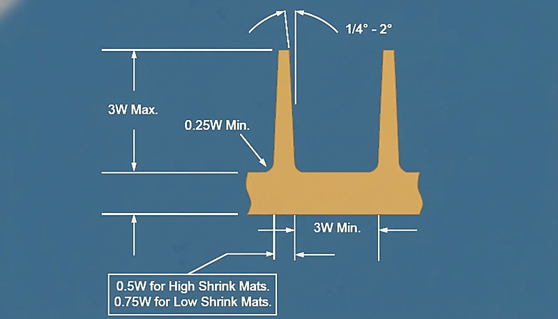
The design process begins with part geometry analysis. The mold engineer reviews the 3D CAD model for wall thickness consistency (target: 2–3 mm for most thermoplastics, with variation under 30%), draft angle (minimum 0.5° on all vertical walls, 1–2° preferred), undercuts that require side actions, and surface finish requirements. This review, called the DFM report, typically identifies five to fifteen improvement opportunities before any machining begins. Gate location is the next critical decision. The gate — the restricted opening through which plastic enters the cavity — determines fill direction, weld line placement, and where the gate mark appears on the finished part.
Our in-house mold manufacturing facility is staffed by 8 senior engineers who collectively bring decades of tooling experience across automotive, medical, and consumer electronics applications. Having the mold shop on the same campus as the molding floor means we catch design-for-manufacturing issues before steel is cut — not after T1 sampling.
Rules of thumb: place the gate at the thickest wall section, keep it away from areas that require high cosmetic quality, and position it so plastic flows from thick to thin (never thin to thick). Poor gate placement causes short shots, weld lines in structurally critical locations, or unacceptable surface blemishes.
Cooling circuit design follows gate location. The cooling system is a network of drilled channels (typically 8–12 mm diameter) that carry temperature-controlled water at 10–40°C through the steel close to the cavity surface. Channel spacing, depth below the cavity surface (typically 1.5× diameter), and coolant flow rate determine how quickly heat is extracted from the plastic. Poorly designed cooling circuits create hot spots that extend cycle time, cause warpage, and introduce dimensional variation between cavities. The ejector system must be designed to push the part out without marking or distorting it.
“Cooling circuit design has the largest impact on cycle time of any mold engineering decision.”真
Cooling accounts for 60–70% of total cycle time. Optimizing cooling channel placement and coolant temperature can reduce cycle time by 20–40% — directly multiplying output without any change to the injection machine or process parameters.
“Draft angles are optional on injection-molded parts.”偽
Draft angles are mandatory, not optional. Without draft, the part grips the steel as it solidifies due to thermal contraction and shrinkage, causing drag marks, sticking, or tool damage. Most production molds require a minimum of 0.5° draft, and textured surfaces need 1–3° to prevent the texture from acting as barbs that lock the part to the steel.
How Much Does an Injection Mold Cost?
Injection mold cost is determined by part complexity, number of cavities, steel grade, tolerance requirements, and the supplier’s location. Understanding the cost drivers helps buyers negotiate effectively and make smarter volume decisions.
| 金型タイプ | Cavities | 複雑さ | Typical Cost Range | リードタイム |
|---|---|---|---|---|
| Prototype / Soft Tooling | 1 | 低い | $3,000 – $10,000 | 2–4 weeks |
| Simple Production Mold | 1–2 | 低い | $8,000 – $20,000 | 4–6 weeks |
| Medium Production Mold | 4–8 | ミディアム | $20,000 – $60,000 | 6–10 weeks |
| Complex Production Mold | 8–16 | 高い | $50,000 – $120,000 | 10–16 weeks |
| High-Cavity Hot-Runner | 16–32+ | 非常に高い | $80,000 – $250,000 | 14–20 weeks |
Cavity complexity is the dominant cost driver, accounting for 40–60% of total mold cost. A simple flat bracket with two through-holes is machined in a few hours per cavity; an automotive mirror housing with internal lattice ribs, four side actions, and a mirror-finish external surface requires 80–200 machining hours. EDM (electrical discharge machining) is used for tight corners, deep ribs, and textures that end mills cannot reach — EDM adds cost and time but is unavoidable on complex cosmetic parts. Number of cavities multiplies machining time but also multiplies output. The economics favor more cavities as annual volume increases.
A common decision framework: single-cavity for under 50,000 parts per year, two- to four-cavity for 50,000–500,000, eight- to sixteen-cavity for 500,000–2,000,000, and 16+ cavities with hot runners for over two million parts annually. Each step up in cavity count roughly doubles mold cost while cutting per-part machine cost by half.
The trade-off is longer shipping time (2–4 weeks by sea) and the need for rigorous supplier qualification.
ZetarMold’s molds are built to DME/HASCO standard bases with hardened steel inserts and come with T1 sample approval included in the quoted price.
“Multi-cavity molds reduce per-part cost significantly at high volumes.”真
A 16-cavity mold running at the same cycle time as a single-cavity tool produces 16 parts per cycle, cutting per-part machine cost by over 90 percent.
“All injection molds look the same regardless of part complexity.”偽
Mold complexity varies enormously. A simple bracket needs a basic two-plate tool, while an automotive door panel requires a 40-ton mold with eight side actions and sequential valve gating.
What Are the Key Mold Components and Their Functions?
The key injection mold components are the cavity, core, runner, gate, cooling channels, vents, ejector system, guide hardware, and support plates. Each component controls a specific part of filling, cooling, alignment, release, or dimensional stability, so a weak component can create defects even when the molding machine settings look correct.
| コンポーネント | 機能 | 一般材料 |
|---|---|---|
| Cavity Insert (A-side) | Forms the visible exterior surface of the part | P20, H13, S136 |
| Core Insert (B-side) | Forms the interior surface and structural features | P20, H13 |
| Sprue Bushing | Receives plastic from machine nozzle into the runner | Hardened tool steel |
| ランナーシステム | Distributes plastic from sprue to all gates | P20 (cold), heated manifold (hot) |
| ゲート | Controls plastic flow rate and direction into cavity | Steel, carbide for high-wear gates |
| エジェクターピン | Push solidified part out of cavity at ejection | H13, nitrided D2 steel |
| 冷却チャンネル | Circulate water to extract heat from plastic | Drilled into A/B plates |
| Leader Pins & Bushings | Align A and B mold halves on closing | Hardened steel, bronze bushing |
| Side Core / Slider | Forms undercut features perpendicular to draw direction | H13, hardened |
| Vents | Allow air to escape cavity during fill (0.02–0.05 mm deep) | Cut into parting line |
Venting is one of the most underappreciated aspects of mold design. If air cannot escape the cavity ahead of the advancing plastic front, it compresses and heats adiabatically — a phenomenon called diesel effect — which can burn the plastic and erode the steel at the last-fill point. Vents are shallow grooves (0.02–0.05 mm deep, 5–10 mm wide) cut into the parting line to allow air out without letting plastic leak out. Insufficient venting is a leading cause of short shots, burn marks, and high injection pressure requirements.
Leader pins and bushings maintain A/B alignment to within 0.005 mm over millions of cycles.
How Do You Maintain an Injection Mold?
A well-maintained injection mold is a long-term capital asset. Neglecting maintenance leads to degraded part quality, unplanned downtime, and expensive repairs. The goal of a mold maintenance program is to keep the tool in T1-sample condition throughout its production life. In our factory, we have seen molds that were neglected for just six months develop corrosion pitting on P20 cavity surfaces — a $15,000 repair that could have been prevented with a standard 50,000-shot preventive maintenance cycle.
Preventive maintenance (PM) should be scheduled by shot count, not calendar time. The standard PM interval for P20 molds running standard resins is every 50,000–100,000 shots. PM tasks include cleaning cavity and core surfaces with approved plastic-safe cleaners, inspecting and lubricating ejector pins and side-action sliding surfaces, checking vents for plastic buildup (which begins to act as a vent blocker after 20,000–30,000 shots), measuring critical dimensions on sample parts to detect wear trends, and inspecting cooling circuit connectors and hoses for leaks. Ejector pins are the highest-wear components in a mold.
They operate in tight clearance bores (H7/h6 fit) at high speed and load every cycle.
Signs of ejector pin wear include drag marks on part surfaces, pin breakage, and out-of-round holes in the ejector plate. A set of spare ejector pins in the correct diameter and length should be kept on-shelf for every active production mold.

How Do You Choose the Right Injection Mold Supplier?
Selecting the wrong mold supplier is the most expensive mistake a product development team can make. A low-quality mold can require three to five revision cycles and six months of delays before producing acceptable parts. Here is what to evaluate before awarding tooling business. First, evaluate machining capability and equipment. A credible mold shop should have CNC machining centers with ±0.005 mm positioning accuracy, EDM (sinker and wire) for complex geometries, CMM (coordinate measuring machine) for dimensional verification, and surface grinders for parting line flatness.
Shops without CMM capability cannot verify that the mold they built matches the design intent — all tolerance claims become guesswork.
Second, require a formal DFM report before tooling begins. Every reputable mold supplier should deliver a written DFM report identifying wall thickness issues, draft angle deficiencies, undercuts requiring side actions, and gate location recommendations. If a supplier quotes and builds without a DFM report, they are either skipping this step (which increases revision risk) or pricing in the expected revision cost without disclosing it. Third, understand the T1 sample approval process. T1 samples are the first parts produced from the completed mold. The buyer should specify acceptable tolerances, surface finish, and measurement protocol before T1 approval begins.
Experienced buyers measure 30–50 critical dimensions on three to five T1 samples from each cavity, not just visual inspection. ZetarMold provides dimensional reports with every T1 submission, showing measured vs. nominal for all specified critical dimensions. Finally, ask about insert molding capability if your parts require embedded metal components. Insert molds need precise insert-placement fixtures and often manual or robotic loading — capabilities that add complexity and require dedicated process expertise.
What Is the Lead Time for Building an Injection Mold?
Lead time from design approval to first T1 samples is one of the most scrutinized variables in new product development. Understanding what drives lead time helps teams plan realistically and avoid schedule surprises. A simple single-cavity P20 mold for a non-critical part can be built and ready for T1 sampling in 3–4 weeks. A medium-complexity four-cavity mold with two side actions typically runs 6–8 weeks. Complex multi-cavity hot-runner tools for automotive or consumer electronics applications commonly require 12–18 weeks.
Any part requiring textured surfaces adds 2–4 weeks for the texturing step, which is performed by a specialty supplier after the steel work is complete.
Frequently Asked Questions About Injection Molds?
よくある質問
射出成形における金型とダイの違いは何ですか?
In injection molding, the term ‘mold’ refers to the steel tool that shapes thermoplastic resin. The term ‘die’ is used in die casting (for metal alloys) and stamping (for sheet metal). In everyday shop-floor conversation, many engineers use the two terms interchangeably when talking about plastic tooling, but technically, molds are used for thermoplastics and thermosets, while dies are used for metals. The key functional difference is that an injection mold operates at relatively low temperature (15–60°C coolant), while a die-casting die must withstand molten aluminum at 650–750°C.
射出成形金型は交換が必要になるまでに何回のショットを生産できますか?
Mold life depends heavily on steel grade and resin abrasiveness. A P20 steel mold running standard ABS or polypropylene will typically last 500,000–800,000 shots before cavity wear becomes visible in part dimensions. H13 hardened steel extends life to 1,000,000–2,000,000 shots. S136 stainless, when properly maintained, can exceed 1,000,000 shots with corrosion-resistant resins. Glass-filled or mineral-filled resins are significantly more abrasive and can reduce mold life by 30–50% compared to unfilled grades. Regular dimensional trending during PM checks catches wear before it causes scrap.
ファミリーモールドとは何か、またいつ使用すべきですか?
A family mold produces multiple different part numbers in a single tool — for example, a left-hand cover and right-hand cover that are mirror images of each other. Family molds reduce upfront tooling cost compared to individual tools for each part, but they introduce process constraints: all parts in the family must use the same resin and color, and they must all fill, pack, and cool at the same settings. If one cavity consistently has defects at acceptable settings for the other cavities, the entire tool must run at a compromise condition. Family molds work best for parts with similar geometry, volume, and similar fill behavior.
ソフトツールとハードツールの違いは何ですか?
A soft tool (also called prototype tooling or rapid tooling) is built from aluminum or unhardened P20 steel to produce low-volume samples quickly and at lower cost — typically $3,000–$15,000 with a 2–4 week lead time. Soft tools are limited to 1,000–50,000 shots and may not hold the tight tolerances of a production mold. A hard tool uses hardened H13, S136, or heat-treated P20 steel designed for 500,000–2,000,000+ shots with production-level tolerances. Teams use soft tools for market testing, pre-production samples, and regulatory submissions before committing to full hard-tool investment.
収縮は射出成形金型設計にどのような影響を与えますか?
All thermoplastic resins shrink when they cool from melt temperature to room temperature. Shrinkage rates range from 0.2% for filled resins to 2.5% for unfilled semi-crystalline materials like nylon or polyethylene. The mold cavity must be cut oversized by the expected shrinkage rate so that the finished part dimensions are at nominal after cooling. If the mold engineer uses the wrong shrinkage value — for example, using the PP shrinkage of 1.5% for a PA66 part that shrinks 1.8% — critical dimensions will consistently miss tolerance. Accurate shrinkage specification, sourced from the resin supplier’s data sheet, is one of the first DFM inputs.
同じ仕様の中国と西洋の金型メーカーのコスト差はどのくらいですか?
For equivalent specifications — same steel grade, same cavity count, same tolerance class, same surface finish — certified Chinese mold suppliers typically quote 40–70% below comparable European or North American tooling prices. ZetarMold’s pricing for a standard 4-cavity P20 mold would be $12,000–$25,000 versus $30,000–$60,000 for the same tool built in Germany or the United States. The primary trade-offs are longer shipping time (3–5 weeks by sea), time zone difference for communication, and the need for thorough supplier qualification. For buyers making high-volume parts, the savings on tooling pay for multiple trips to China for factory audits.
射出成形金型は作製後に修正できますか?
Yes, most injection molds can be modified after initial construction. Adding steel to the cavity reduces a dimension; removing steel increases a dimension. Common post-build modifications include relocating gate positions, adding or removing ejector pins, adjusting vent depth, adding texture, and modifying side-action geometry. Modifications that require adding steel (welding) are more complex and add 1–3 weeks. Modifications that only require machining (removing steel) are faster. Changes that require major structural rework — moving the parting line, changing the mold base size, completely redesigning the runner layout — are usually more expensive than building a new tool.
新しい射出成形金型を受け取る際、どのような品質チェックを行うべきですか?
サプライヤーから新しい金型を受け取る際、バイヤーは以下の点を確認すべきです:金型が承認図面と一致していること(金型ベース寸法、部品に刻印された鋼材グレード、キャビティ数を確認);T1寸法報告書を確認し、少なくともキャビティごとに3つの部品から指定された全ての重要寸法を測定;パーティングラインの状態(平坦さ、バリ、ベント深さ)を点検。冷却回路の流量と圧力損失をテスト(金型設計仕様と一致すること);エジェクタシステムを手動で作動させ、スムーズで引っかかりのない動作を確認;公称プロセス条件で50〜100ショットを試運転し、サイクルタイムを監視し、全ての重要寸法を記録すること。


