 Vai al contenuto

Se hai trascorso del tempo attorno allo stampaggio a iniezione, avrai sentito i termini sprue1, runner2, e cancello3 scambiati come se significassero la stessa cosa. Non è così. Confonderli può portare a una cattiva progettazione dello stampo, spreco di materiale e parti che non si riempiono mai correttamente.
Dopo oltre 20 anni di costruzione di stampi e produzione nella nostra fabbrica di Shanghai, abbiamo visto ogni errore di sistema runner possibile. Questo articolo spiega esattamente cosa fa ogni componente, come differiscono e quali scelte progettuali contano davvero in officina.
- Lo sprue è il primo canale verticale dall'ugello della macchina allo stampo.
- I runner distribuiscono il fuso orizzontalmente dallo sprue ai singoli gate delle cavità.
- I gate sono il punto più stretto — controllano il flusso, il congelamento e la separazione del pezzo.
- I sistemi cold runner producono scarto; i sistemi hot runner lo eliminano ma costano più inizialmente.
- La selezione del tipo di gate influisce direttamente sulla qualità della parte, sul tempo di ciclo e sul lavoro di post-processing.
Cos'è uno Sprue nello Stampaggio a Iniezione?
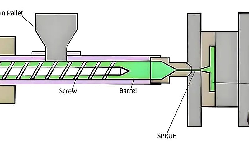
Uno sprue è il primo e più grande canale nel sistema di alimentazione. Inizia all'ugello della macchina, attraversa la piastra superiore dello stampo e si collega alla rete runner. Pensalo come la linea di alimentazione principale — tutto scorre prima attraverso qui.
In un tipico stampo a due piastre, lo sprue è un foro conico (conico) perforato attraverso il bushing dello sprue. Il taper — tipicamente da 1 a 3 gradi per lato — esiste così che lo sprue solidificato possa essere ejectato pulito. Un sprue con pareti rette si incastrerà e bloccherà lo stampo ogni ciclo.
Le dimensioni chiave sono importanti. Il diametro grande dello sprue all'interfaccia dell'ugello tipicamente corrisponde o supera leggermente l'orifizio dell'ugello della macchina (3–6 mm per la maggior parte dello stampaggio generico). Il piccolo end alimenta il runner. Se lo sprue è troppo stretto, si ottiene un calo di pressione eccessivo proprio all'inizio del fill. Se è troppo largo, sprechi materiale e prolungi il tempo di cooling.
Nella nostra fabbrica di Shanghai, ZetarMold ha oltre 20 anni di esperienza nello stampaggio a iniezione e nella costruzione di stampi, gestisce 47 macchine per stampaggio a iniezione da 90T a 1850T e supporta progetti con costruzione interna di stampi. Per il design dello sprue e del runner, questo è importante perché lo stesso stampo può comportarsi diversamente quando passa dalla pressa di prova alla pressa di produzione.
Cos'è un runner nello stampaggio a iniezione?
Un runner è la rete di canali orizzontali che indirizza la plastica fusa dal fondo dello sprue a ogni gate della cavità. In uno stampo multi-cavità stampaggio a iniezione stampo, il sistema di runner è la spina dorsale della distribuzione: determina se ogni cavità si riempie allo stesso tempo e pressione, o se si ottengono colpi corti in alcune cavità e sfogo sovraccarico in altre.
I runner hanno diversi profili trasversali. I più comuni sono:
Full-round — Sezione trasversale circolare. Rapporto superficie/volume ottimo, significa la minima perdita di calore e il minor calo di pressione. Richiede lavorazione su entrambe le parti dello stampo, quindi il costo di tooling è più alto.
Trapezoidale — Lavorato in una sola metà dello stampo. Più facile ed economico da tagliare. Il compromesso è una leggera maggiore perdita di calore e resistenza alla pressione.
Trapezio modificato (forma U) — Un ibrido che migliora il trapezio standard con angoli arrotondati, offrendo migliori caratteristiche di flusso rimanendo lavorabile su un solo lato.
Il diametro del runner varia tipicamente da 3 mm a 10 mm a seconda delle dimensioni del pezzo, della viscosità del materiale e della lunghezza del flusso. Nel nostro laboratorio, raramente scendiamo sotto i 4 mm per qualsiasi cosa oltre il micro-stampaggio — al di sotto di ciò, le perdite di pressione aumentano rapidamente, specialmente con le plastiche tecniche ad alta viscosità.
“Il diametro del runner nella maggior parte degli stampi di produzione varia da 3 mm a 10 mm.”Vero
Vero. Questo è l'intervallo standard. Runner più piccoli creano una perdita di pressione eccessiva, mentre runner più grandi sprecano materiale e prolungano il tempo di ciclo.
“I runner sono sempre lavorati su entrambe le parti dello stampo.”Falso
Falso. I runner trapezoidali e a forma di U sono lavorati su una sola metà dello stampo. Solo i runner completamente rotondi richiedono lavorazione su entrambi i lati.
Cos'è un gate e come differisce da sprue e runner?
Un gate è il restringimento più stretto tra il runner e la cavità dello stampo. È l'ultima porta che la plastica attraversa prima di entrare nella cavità. I gate svolgono quattro funzioni critiche che determinano direttamente la qualità del pezzo e l'efficienza produttiva.
1. Controllo del flusso. Il gate limita e dirige il melt. Un gate più piccolo aumenta la velocità di shear, che riscalda il materiale attraverso la frizione viscosa e riduce temporaneamente la viscosità — aiutando a riempire le sezioni sottili.
2. Sigillo di congelamento. Una volta che la cavità è riempita, il gate è la prima cosa a solidificarsi. Questo sigilla la cavità in modo che il materiale compresso non possa rifluire nel runner quando la pressione di iniezione diminuisce.
3. Punto di separazione. Dopo l'espulsione, il gate è dove il pezzo si separa dal sistema runner. Un gate ben progettato si stacca pulito o richiede una rifinitura minima.
4. Controllo del packing. La dimensione del gate e il tempo di freeze controllano direttamente la quantità di materiale di packing che entra nella cavità.
Un gate troppo grande significa un lungo riempimento – e possibile sovraccarico, sfogo o elevata tensione residua. Troppo piccolo, e il gate si congela prima che la cavità sia completamente riempita, causando avvallamenti o vuoti.
Qual è il percorso completo di alimentazione dall'ugello alla cavità?
Il percorso di alimentazione completo dall'ugello alla cavità è definito dalla funzione, dai vincoli e dai compromessi spiegati in questa sezione. Il percorso completo della plastica fusa attraverso un stampo a iniezione segue questa sequenza: Cilindro della macchina → Punta dell'ugello → Sprue (verticale, attraverso la piastra superiore di bloccaggio) → Runner (orizzontale, attraverso la superficie di separazione) → Gate (stretta strozzatura) → Cavità.
Ogni fase rappresenta una riduzione della sezione trasversale. Lo sprue è il canale più grande, il runner è più piccolo e ramificato, e il gate è la strozzatura più piccola. Questo restringimento è intenzionale: mantiene la velocità di flusso e la pressione fino all'ingresso della cavità.
C'è anche un pozzetto per il bolo freddo alla base dello sprue, opposto all'estrattore dello sprue. Il suo compito è catturare il bolo freddo e lento di plastica che si trova sulla punta dell'ugello tra i cicli. Senza di esso, quel tappo freddo viaggerebbe lungo il runner e potrebbe bloccare un gate o causare una macchia visibile sul pezzo.
“Il cold slug well cattura la plastica solidificata dalla punta dell'ugello tra i cicli.”Vero
Vero. Senza un cold slug well, il materiale solidificato della punta dell'ugello entrerà nel sistema runner e potrebbe bloccare un gate o creare difetti superficiali sulla parte stampata.
“Il gate è il canale più grande nel sistema di alimentazione.”Falso
Falso. Il gate è la strozzatura più piccola. Lo sprue è il canale più grande, il runner è medio, e il gate è il punto più stretto tra il runner e la cavità.
Quale sistema dovresti utilizzare: cold runner o hot runner?
Questa è una delle decisioni di progettazione più importanti nella costruzione di qualsiasi stampo. Il tipo di sistema di runner influisce sugli sprechi di materiale, sul tempo di ciclo, sulla qualità delle parti e sul costo degli utensili. Comprendere i compromessi aiuta a fare la scelta giusta per il volume di produzione e il budget.
Un sistema cold runner è l'approccio tradizionale e meno costoso. I canali del runner non sono riscaldati — sono semplicemente lavorati nell'acciaio dello stampo. Dopo ogni ciclo, il runner di plastica solidifica insieme alle parti e viene espulso. Quel runner solidificato è un spreco (o materiale da riciclare), tipicamente dal 5% al 30% del peso totale dello shot, dipendendo dalla geometria della parte.
Un sistema hot runner utilizza resistenze a cartuccia, termocoppie e blocchi manifold per mantenere la plastica nei canali del runner sempre allo stato fluido. Nessun runner viene espulso come spreco — solo le parti. Questo salva materiale, riduce il tempo di ciclo (nessun runner da raffreddare e espellere), e spesso permette cambi di colore o materiale più rapidi. Il compromesso è un costo degli utensili significativamente più alto e una maggiore complessità di manutenzione.
Ecco una comparazione pratica:
| Criteria | Cold Runner | Corridore caldo |
|---|---|---|
| Costo degli utensili | Inferiore ($3K–$15K meno) | Più alto (manifold riscaldato + controllori) |
| Materiale di scarto | 5–30% per colpo (sfrido del runner) | Quasi zero (no runner solidificato) |
| Tempo di ciclo | Longer (runner must cool) | Più breve (nessun raffreddamento del runner necessario) |
| Manutenzione | Semplice, robusto | Complesso (riscaldatori, termocoppie, perdite) |
| Cambio colore | Facile (spurgare l'intero sistema) | Più lento (fuso residuo nel manifold) |
| Part Quality | Segni dell'iniettore, possibile vestigio | Iniettori più puliti, iniettore termico o valvola |
| Il migliore per | Volume medio-basso, frequenti cambi di colore | Alti volumi, tolleranze strette, resine costose |
{“type”:”factory_insight”,”fact_ids”:[“equipment.injection_machines_47″,”equipment.tonnage_90_1850″],”text”:”Nel nostro stabilimento di Shanghai, gestiamo 47 macchine per stampaggio a iniezione da 90T a 1850T, producendo parti con stampi sia a runner freddo che caldo. Per lavori medicali e di elettronica di consumo ad alto volume, gli hot runner vincono quasi sempre sul costo totale di proprietà una volta superate circa 100.000 cicli.”}
Quali sono i tipi di gate più comuni?
I tipi di iniettore più comuni sono le categorie principali o le opzioni spiegate in questa sezione. La selezione dell'iniettore non è un esercizio teorico — determina direttamente se il componente si riempie correttamente, quanto post-processing richiede e se la produzione automatizzata è possibile. Qui sono i sei tipi di iniettore che si incontrano più spesso negli stampi di produzione:
1. Gate diretto (a sprue). Il gate più semplice — lo sprue alimenta direttamente la cavità senza runner. Utilizzato per stampi a singola cavità che producono parti grandi e a pareti spesse come secchi o custodie. Bassa perdita di pressione, ma lascia un segno di gate grande e visibile e non può essere utilizzato per layout multi-cavità.
2. Gate laterale (edge). Il tipo di gate più versatile, situato sulla superficie di separazione al bordo della cavità. Facile da lavorare, facile da regolare nelle dimensioni e funziona con la maggior parte dei materiali. Gli svantaggi sono il vestigio visibile del gate e la necessità di degating manuale.
3. Gate sottomarino (a tunnel). Il canale del runner si inclina sotto la linea di separazione ed entra nella cavità dal lato inferiore o da una superficie interna. Quando lo stampo si apre, il runner inclinato taglia automaticamente il gate dal pezzo — consentendo una produzione completamente automatizzata senza segni di gate visibili sulla superficie estetica. Non raccomandato per materiali fragili come PC o PMMA.
Gli iniettori submarine possono permettere produzione completamente automatizzata perché l'iniettore si taglia durante l'apertura dello stampo.Vero
Vero. Il design del tunnel angolato causa l'autoseparazione dell'iniettore dal componente durante l'apertura dello stampo, eliminando la necessità di degating manuale.
“I gate a punta funzionano con stampi standard a due piastre.”Falso
Falso. Gli iniettori pin-point richiedono uno stampo a tre piastre (doppia superficie di separazione) perché l'iniettore deve essere estratto dal lato fissato durante l'apertura dello stampo. Stampi standard a due piastre non possono ospitare questo tipo di iniettore.
4. Iniettore pin-point. Un iniettore di diametro molto piccolo (tipicamente 0.5–1.5 mm) che lascia vestigio minimo e si autosepara durante l'estrazione. Richiede uno stampo a tre piastre. Alta perdita di pressione di iniezione, ma eccellente per parti cosmetic e stampi multi-cavità.
5. Iniettore fan. Un iniettore largo e piatto che distribuisce il melt su un fronte ampio. Ideale per parti thin-walled dove si deve evitare jetting o difetti di alto shear. Comune in pannelli flat e cover per lenti.
6. Valvola a spillo (solo hot runner). Uno spillo azionato meccanicamente che apre e chiude l'orifizio del gate. Fornisce il segno di gate più pulito, un controllo preciso sul timing di apertura del gate, ed è utilizzato in applicazioni di fascia alta multi-cavità e riempimento sequenziale. L'opzione più costosa.

Come influisce la dimensione del gate sulla qualità del pezzo?
La dimensione dell'iniettore è il punto di controllo per la velocità di riempimento, il tempo di packing e la qualità della separazione. Se è errata, i difetti si manifestano rapidamente.
Iniettore troppo piccolo: L'alta velocità di shear attraverso l'iniettore causa un eccessivo calore da attrito, che può degradare resine sensibili alla temperatura. L'iniettore inoltre si solidifica troppo presto, interrompendo la pressione di packing prima che la cavità sia completamente compensata per il shrinkage. Risultato: sink marks, vuoti e parti sotto-pressate. Si vede anche alta caduta di pressione che può causare short shot in stampi multi-cavità.
Iniettore troppo grande: Tempo di packing prolungato, sovra-packing vicino all'iniettore e alta tensione residua. Il vestigio dell'iniettore è più grande e più difficile da rimuovere completamente. Il tempo di ciclo aumenta perché la sezione spessa dell'iniettore richiede più tempo per solidificarsi.
Nella pratica, iniziamo con un'area della sezione trasversale del gate pari circa al 50–70% della sezione di parete più sottile del pezzo, quindi regoliamo in base ai risultati della simulazione di flusso nello stampo. La lunghezza del land del gate (la sezione rettilinea) viene mantenuta breve — tipicamente 0,5–1,5 mm — per minimizzare la perdita di pressione. Qualsiasi lunghezza maggiore è solitamente pressione sprecata.
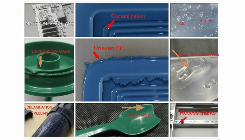
Quali problemi si verificano quando il sistema runner è mal progettato?
Un sistema di runner progettato male è una causa diretta di riempimento sbilanciato, perdita di pressione, slug freddi e resina sprecata. Nella nostra fabbrica, diagnosticiamo questi problemi seguendo il percorso del fuso dall'ugello alla cavità prima di modificare le impostazioni della macchina.
Riempimento sbilanciato in stampi multi-cavità. Quando le lunghezze o i diametri dei runner variano, alcune cavità si riempiono per prime e altre rimangono indietro. Le cavità che si riempiono per prime vengono sovracompattate mentre quelle che si riempiono dopo risultano incomplete. La soluzione è un design bilanciato del runner — uguale lunghezza di flusso e sezione trasversale per ogni cavità, o compensazione della lunghezza di flusso utilizzando diametri di runner diversi.
Caduta di pressione eccessiva. Runner lunghi e stretti con troppe curve dissipano la pressione di iniezione prima che il fuso raggiunga la cavità. Se hai bisogno di 120 MPa in cavità ma perdi 80 MPa nel sistema di runner, hai bisogno di una macchina più grande — o di un layout del runner migliore.
Slug freddi che entrano nella cavità. Se il pozzo per lo slug freddo è mancante o troppo piccolo, il plug solidificato dalla punta dell'ugello viaggia nel runner e blocca un iniettore. Questo appare come short shot intermittenti o imperfezioni superficiali che si presentano casualmente.
Runner waste eccessivo. In stampi con runner freddo, runner sovradimensionati (un margine di sicurezza comune) sprecano materiale. In produzione ad alto volume con resine ingegneristiche costose (PEEK, PPS, LCP), anche pochi grammi per shot si sommano a migliaia di dollari per anno.
Come si ottimizza il design del runner per stampi multi-cavità?
L'ottimizzazione dello stampo multi-cavità è dove i progettisti di stampi esperti guadagnano il loro valore. L'obiettivo è semplice: ogni cavità si riempie alla stessa velocità, alla stessa pressione, producendo parti identiche. Raggiungerlo richiede attenzione a tre fattori.
Bilanciamento geometrico (runner naturalmente bilanciato). Disporre il runner in modo che il percorso del flusso dallo sprue a ogni cavità abbia lunghezza, numero di curve e sezione trasversale identici. Un pattern H o layout radiale raggiunge questo naturalmente. Questo è lo standard di riferimento, ma non sempre si adatta ai vincoli della base dello stampo o alle esigenze di layout del componente.
Compensazione della lunghezza del flusso (runner artificialmente bilanciato). Quando il bilanciamento geometrico è impossibile, regolare i diametri dei runner per equalizzare la caduta di pressione verso ogni cavità. Una cavità più distante dallo sprue riceve un runner più largo per compensare la perdita di attrito extra. Questo richiede una simulazione accurata del flusso nello stampo.
Dimensionamento del gate come regolazione finale. Anche con corridori bilanciati, piccole variazioni nella geometria della cavità (pesi diversi delle parti, spessori delle pareti) possono causare squilibri. Regolare leggermente le dimensioni dei singoli gate è il passo finale di messa a punto. Questo viene fatto durante la campionatura dello stampo – stampiamo colate di prova, misuriamo i pesi delle cavità e regoliamo i gate con incrementi di 0,1 mm.
{"type":"factory_insight","fact_ids":["facility.in_house_mold_manufacturing","company.experience_20_years"],"text":"Con la nostra struttura interna di produzione stampi e oltre 20 anni di esperienza nella costruzione di attrezzature, progettiamo e regoliamo abitualmente stampi multi-cavità fino a 64 cavità per componenti ad alto volume per connettori e medicali."}
"In un sistema di corridori naturalmente bilanciato, ogni cavità ha un percorso di flusso identico a partire dal canale di colata."Vero
Vero. I corridori geometricamente bilanciati utilizzano layout a H o radiali per garantire uguale lunghezza del flusso, curve e sezione trasversale per ogni cavità, producendo parti uniformi.
“Il bilanciamento del runner è necessario solo per stampi con più di 16 cavità.”Falso
Falso. Anche un stampo con 2 cavità può soffrire di un bilanciamento di riempimento se le lunghezze dei runner differiscono. Il bilanciamento dei runner è importante per qualsiasi stampo multi-cavità, indipendentemente dal numero di cavità.
Quali sono le principali differenze tra sprue, runner e gate?
Se necessiti una comparazione rapida, questa tabella riassume le principali differenze tra sprue, runner e gate:
| Caratteristica | Materozza | Corridore | Cancello |
|---|---|---|---|
| Posizione | Verticale, attraverso la piastra superiore | Orizzontale, sulla superficie di separazione | Tra runner e cavità |
| Funzione | Collega l'ugello al sistema di runner | Distribuisce il materiale fluido a tutte le cavità | Controlla l'entrata nella cavità |
| Dimensione | Canale più grande (3–10 mm diam.) | Medio (3–8 mm diam.) | Più piccolo (0,3–3 mm di diametro) |
| Cross-section | Conico conico | Circolare, trapezoidale o a forma di U | Rettangolare stretto o circolare |
| Solidifica | Primo a ricevere il fuso, lento a solidificarsi | Solidifica con il prodotto | Prima sezione a solidificare |
| Espulsione | Estratto dall'estrattore di colata / sottosquadro | Espulso con il pezzo sulla linea di separazione | Si separa dal pezzo durante l'espulsione |
| Consiglio di progettazione | Conicità di 1–3° per lato per un rilascio pulito | La forma completamente rotonda è la più efficiente | Gate più piccolo che riempie il prodotto |
Domande frequenti
Qual è la Differenza tra un Attacco e un Canale di Colata?
Un canale di colata è il canale verticale che collega l'ugello della macchina per lo stampaggio a iniezione al sistema di canali di distribuzione dello stampo, mentre un canale di distribuzione è il canale orizzontale che distribuisce il fuso dal canale di colata ai singoli cancelli della cavità. Il canale di colata è il primo canale che la plastica attraversa dopo la punta dell'ugello e passa attraverso la piastra di serraggio superiore dello stampo. I canali di distribuzione seguono il canale di colata e si ramificano per raggiungere ogni cavità. In termini di dimensioni, il canale di colata è tipicamente il singolo canale più grande nel sistema di alimentazione, mentre i canali di distribuzione sono ramificati e leggermente più piccoli in sezione trasversale.
Un Modello Può Funzionare Senza un Colatoio?
Solo in stampi con runner caldi con una connessione diretta ugello-manifold, dove l'ugello riscaldato alimenta direttamente nel manifold senza un bushing del sprue convenzionale. In molti stampi standard con runner freddi a due piastre, il sprue è essenziale perché collega l'ugello stazionario della macchina sulla parte fissa e il sistema di runner della parte mobile dello stampo. Senza esso, non c'è un canale sigillato per trasportare il materiale fluido dalla canna della macchina nelle cavità dello stampo. I sistemi con runner caldi possono eliminare completamente il sprue usando un bushing del sprue riscaldato o un gate diretto.
Perché lo Sprue è Conico negli Stampi a Iniezione?
La conicità (1–3 gradi per lato) crea un angolo di sformo che permette al sprue solidificato di rilasciarsi pulito dal bushing del sprue durante l'apertura dello stampo. Un canale cilindrico con pareti rette si aggrapperebbe alla superficie metallica per frizione e contrazione termica, bloccando il sistema di estrazione e potenzialmente danneggiando la superficie dello stampo dopo cicli ripetuti. La conicità garantisce che il sprue si estragga dal bushing senza problemi in ogni ciclo, cosa cruciale per una produzione automatizzata affidabile, tempi di ciclo consistenti e una lunga vita dello stampo.
Cosa Succede Se il Corridore È Troppo Piccolo?
Un runner sottodimensionato crea un eccessivo calo di pressione tra l'ugello della macchina e la cavità, che può causare mancate riempiture, elevati requisiti di pressione di riempimento e un aumento del riscaldamento da taglio nel fuso. La macchina potrebbe dover operare al suo limite di pressione massimo, senza margine per aggiustamenti del processo o variazioni di viscosità del materiale durante la produzione. Negli stampi multi-cavità, i runner sottodimensionati rendono anche molto più difficile bilanciare il riempimento delle cavità, portando a una qualità dei pezzi inconsistente, variazioni dimensionali tra le cavità e tassi di scarto complessivi più elevati.
Ogni Stampo Necessita di un Pozzetto Freddo?
In stampi con runner freddi, sì — cattura il residuo solidificato dell'ugello che si forma tra i cicli di iniezione. Senza esso, quel residuo freddo entra nel sistema di runner e può bloccare un gate o creare una imperfezione superficiale visibile sul prodotto finito. In stampi con runner caldi, il materiale rimane sempre fluido nel manifold riscaldato, quindi i well per i residui freddi non sono necessari perché non c'è materiale solidificato da catturare. Tuttavia, la maggior parte degli stampi con runner freddi dovrebbe sempre includere un well per residui freddi dimensionato correttamente alla base del sprue.
Come si sceglie tra sistemi di runner freddi e hot runner?
Utilizzare sistemi a canale freddo per produzioni a medio-basso volume, applicazioni che richiedono frequenti cambi di colore o quando il budget per gli stampi è limitato. Passare a canale caldo per produzioni ad alto volume (tipicamente sopra le 100.000 cicli), resine ingegneristiche costose dove lo spreco di canale è oneroso, o quando la riduzione del tempo di ciclo è critica per la redditività. La maggior parte degli stampi di produzione che realizzano oltre 500.000 pezzi all'anno utilizzano sistemi a canale caldo perché il risparmio di materiale e i cicli più rapidi compensano il maggiore investimento iniziale nello stampo già nella prima produzione. Fate i calcoli prima di scegliere. Confrontate il volume annuale, il peso del canale, il prezzo della resina, la frequenza di cambio colore, l'automazione richiesta, il budget dello stampo e le competenze di manutenzione. Un canale caldo può essere un investimento solido, ma solo quando i risparmi di produzione sono maggiori della complessità aggiunta.
Cos'è il Bilanciamento dei Runner e Perché è Importante?
Il bilanciamento del runner garantisce che tutte le cavità di uno stampo multi-cavità si riempiano simultaneamente e a pressione uguale, producendo pezzi consistenti in tutte le cavità ad ogni ciclo. Si ottiene attraverso la disposizione geometrica (percorsi di flusso uguali utilizzando disegni a H o radiali del runner) o regolando i diametri individuali dei runner per compensare le diverse lunghezze di flusso verso ciascuna cavità. I runner sbilanciati causano il sovra-riempimento di alcune cavità (con conseguenti sbavature, elevata tensione residua e problemi dimensionali) mentre altre sono sotto-riempite (mancate riempiture, avvallamenti e vuoti), portando a una qualità dei pezzi inconsistente e a tassi di scarto più elevati.
Quale Tipo di Cancello Lascia il Segno Più Piccolo sul Pezzo?
I cancelli a spillo e i cancelli sottomarini (tunnel) lasciano la minima traccia visibile sulla superficie del pezzo, tipicamente un punto o una piccola fossetta di diametro inferiore a 1 mm. I cancelli a valvola nei sistemi hot runner lasciano il segno più pulito di tutti — una piccola traccia circolare senza rilievo, perché lo spillo della valvola taglia il cancello a filo con la superficie del pezzo durante la chiusura. I cancelli diretti e i grandi cancelli di bordo lasciano i segni più visibili sul pezzo stampato, che spesso richiedono operazioni secondarie di rifinitura, levigatura o finitura cosmetica per essere rimossi prima che il pezzo possa essere spedito.
Come può ZetarMold aiutarti con la progettazione del tuo stampo?
Scegliere la giusta configurazione di sprue, runner e gate non è un esercizio da manuale — dipende dalla geometria del pezzo, dal materiale, dal volume di produzione e dai requisiti di qualità. In ZetarMold, progettiamo e costruiamo stampi internamente con 47 macchine per stampaggio a iniezione (90T–1850T) ed esperienza su oltre 400 materiali plastici. Se state cercando uno fornitore di stampaggio a iniezione, il nostro team di ingegneria può guidarvi dalla DFM alla produzione.
Sia che abbiate bisogno di uno stampo a canale freddo semplice per una produzione breve o di un sistema di canale caldo di precisione per una produzione di milioni di pezzi, il nostro team può aiutarvi a fare le cose bene fin dal primo tentativo.
Richiedi un Preventivo Gratuito → Invia il tuo modello 3D e ti restituiremo feedback DFM, raccomandazioni di progettazione dello stampo e una tempistica di produzione entro 48 ore.
-
sprue: sprue si riferisce a uno sprue è il canale verticale primario che convoglia la plastica fusa dall'ugello della macchina per stampaggio a iniezione nel sistema di runner di uno stampo. ↩
-
canale di distribuzione: runner si riferisce a un runner è il sistema di canali orizzontali che distribuisce la plastica fusa dallo sprue ai singoli gate delle cavità in uno stampo multi-cavità o multi-gate. ↩
-
gate: il gate si riferisce alla stretta apertura tra il canale e la cavità dello stampo dove la plastica fusa entra nella geometria del pezzo. ↩


