 Skip to content

La séquence sûre consiste à sécher d'abord, puis le profil de vitesse, ensuite le pack and hold, puis la température de fusion, et enfin la température du moule. Changer les cinq paramètres en même temps crée un rapport d'essai bien présenté mais un enregistrement de cause racine inutile. Conservez un réglage de référence, ajustez une variable et marquez les échantillons avec le numéro exact de tir. venting1, or an internal vacuum void2 caused by shrinkage. If you treat every bubble by simply raising pressure, you may hide one symptom and create three new ones.
This guide gives you a factory-style diagnosis path for moulage par injection bubbles. The goal is to identify the bubble type first, then adjust material drying, machine settings, gate location, mold venting, or part design in the right order. That saves trial time and keeps the moule d'injection from being blamed too early.
- Identify bubble type before changing pressure.
- Moisture, trapped air, and voids need different fixes.
- Venting and gate location often decide success.
- Drying records matter more than operator memory.
- Design changes beat heroic process tuning.
What causes air bubbles in injection molded parts?
Air bubbles are caused by trapped gas, material moisture, melt degradation, poor packing, or geometry that blocks gas escape. The first job is to decide whether the bubble is near the surface, inside a thick wall, at the end of flow, around a rib, or close to the gate.
A true air trap3 usually appears where two melt fronts meet or where the last area of the cavity fills. The plastic seals the gas before the vent can release it. You may see a bubble, burn mark, short shot, or shiny weak spot. If the defect location follows the flow path every cycle, suspect air movement and venting before blaming the resin.
A vacuum void behaves differently. It often forms inside a thick boss, rib base, or heavy wall where the outside freezes first and the center keeps shrinking. The surface may look acceptable, but cutting the part reveals a hollow space. In our experience, vacuum voids are common when buyers request thick walls for strength, then ask why the part has internal bubbles.

In our factory in Shanghai, ZetarMold runs 47 injection molding machines from 90T to 1850T and has experience with 400+ plastic materials. That range matters because bubbles in a small ABS cover, a large PP shell, and a glass-filled nylon housing can have different root causes even when the defect looks similar.
« L'emplacement de la bulle est l'indice le plus rapide pour la cause racine. »Vrai
A bubble at the end of fill points toward trapped air or poor venting, while a bubble inside a thick section points toward shrinkage, packing, or cooling imbalance.
« Toutes les bulles peuvent être corrigées en augmentant la pression d'injection. »Faux
Higher pressure can help some packing voids, but it can worsen flash, stress, burn marks, shear heating, and overpacking if the root cause is moisture or trapped air.
How do you tell trapped air from moisture or vacuum voids?
Trapped air is location-stable, moisture is often random, and vacuum voids are usually hidden inside thick geometry. Use location, timing, cut inspection, drying records, and process response to separate them.
Start with a simple cut test. Slice the part through the defect and inspect the wall. If the hollow space is central inside a thick area, treat it as shrinkage or packing first. If the bubble opens to the surface or sits near the end of fill, inspect vents, weld lines, and flow hesitation. If the defect changes after proper drying, moisture was probably part of the problem.
A drying log is not paperwork decoration. Hygroscopic materials such as nylon, PC, ABS, PBT, and TPU can release steam during molding when moisture is too high. Non-hygroscopic materials can still carry surface moisture if stored cold or exposed to humid air. We recommend recording drying temperature, drying time, dew point, hopper exposure time, and resin lot for every bubble investigation.
Do not ignore smell or discoloration. If the material smells burnt, turns yellow, or shows black specks, the bubble may come from degradation rather than normal air. Excessive barrel temperature, long residence time, high screw speed, dead zones in the barrel, or contaminated regrind can all generate gas before the plastic reaches the cavity.
| Symptom | Likely cause | First check |
|---|---|---|
| End-of-fill bubble | Air trap | Vent depth and flow path |
| Random splay marks | Moisture or volatiles | Drying log and resin storage |
| Internal hollow core | Vacuum void | Wall thickness and packing |
| Burned bubble | Gas compression | Venting and injection speed |
After the first classification, keep a sample board. Put one part from each trial setting on the board and write the resin lot, drying record, melt temperature, injection speed profile, holding pressure, and cavity number next to it. That simple habit stops the team from arguing by memory. It also shows whether a fix is repeatable or whether one lucky shot is being mistaken for a stable process in normal production today again. Keep photos, cut samples, and settings together for later comparison during team review safely.
How should process settings be adjusted to remove bubbles?
Process settings should be adjusted only after material drying and defect type are confirmed. For trapped air, reduce excessive injection speed near the end of fill or use staged injection. For vacuum voids, improve packing pressure, holding time, gate freeze control, and cooling balance.
The safe sequence is drying first, then speed profile, then pack and hold, then melt temperature, then mold temperature. Changing all five at once creates a nice looking trial report and a useless root-cause record. Keep one reference setting, adjust one variable, and mark samples with the exact shot number.
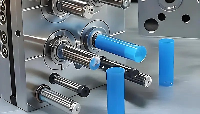
Moule d'injection et produit moulé par injection
Packing settings help when the defect is a vacuum void. Increase holding pressure carefully, extend holding time until the gate freezes, and confirm cushion stability. If the gate freezes too early, extra hold time does nothing. Link the correction to Temps de production du moulage par injection, because longer cooling and holding can change both cost and output.
« Un profil de vitesse d'injection étagé peut réduire les pièges à air en fin de remplissage. »Vrai
Slowing the melt front near the last fill area can reduce gas compression and gives venting more time to release displaced air.
« Un temps de maintien plus long élimine toujours les vides internes. »Faux
Hold time only works while the gate is open. If the gate has already frozen, pressure cannot reach the shrinking material inside the part.
Part weight is a useful process signal here. If higher holding pressure increases part weight and reduces the bubble, packing was probably weak. If part weight stops increasing but the void remains, the gate may already be frozen or the thick section may be too isolated from the gate. That distinction matters because one case is a setting problem and the other may require gate or design changes. Keep the samples and part weights together so the next shift can repeat the same conclusion without guessing later safely enough.
When does the mold need venting or gate changes?
Mold venting is needed when the bubble repeats in the same location after drying and process tuning. Stable location means stable flow behavior. If the same corner, rib end, boss, or weld line fails every time, the mold is telling you where the air is trapped.
Venting should be placed at the real last-fill area, not only where the designer guessed during tool build. Flow simulation helps, but short-shot studies are often more practical on the shop floor. Fill the part at 80%, 90%, and 95%, then watch where the melt front stops and where air has no escape path.
Gate location also matters. A gate that pushes flow around a tall rib or into a blind pocket can trap air even if the vent depth is correct. Moving the gate, adding an overflow tab, changing runner balance, or improving parting-line venting may be more reliable than trying to force gas through a sealed section. For buyers, this is why early DFM review beats late tool repair.
If you are comparing suppliers for a cosmetic or airtight project, ask how they diagnose bubbles before awarding the tool. A good sourcing guide should check whether the supplier can explain venting, drying, and packing instead of promising that every defect is easy to fix later.
How can part design prevent bubbles before tooling?
Bubble-safe part design is mainly about uniform walls, open flow paths, and geometry that lets air escape. Avoid thick sections, blind pockets, poor rib transitions, and long flow paths that trap gas. A design that looks strong in CAD can be difficult to pack and vent in steel.
Start with wall thickness. Thick bosses and ribs create shrinkage centers, while sudden wall transitions create flow hesitation. Use coring, ribs, gussets, and gradual transitions instead of solid blocks. If a thick area is unavoidable, place the gate so packing pressure can reach it before gate freeze and review expected retrait du moule early.
Draft and texture can also affect bubble diagnosis. A rough texture may hide small surface gas marks, but it will not fix trapped air. Deep ribs can need extra vents or ejector-area venting. Thin-wall sections may need higher speed, but higher speed can compress gas harder if the vent path is weak.
The best review question is simple: where will the air go? If nobody can answer that before steel cutting, expect trial delays. Mark last-fill zones, weld lines, thick sections, and cosmetic surfaces on the DFM review. That one drawing often prevents days of machine-side guessing.

What is the fastest troubleshooting workflow for bubbles?
The fastest troubleshooting workflow for bubbles is defined by the function, constraints, and tradeoffs explained in this section. The fastest troubleshooting workflow is to classify the bubble, verify drying, run a short-shot study, adjust one process variable, and only then modify the mold. This order protects you from chasing the wrong cause and keeps the investigation useful for future production.
Use this sequence: inspect location, cut the part, confirm resin and drying, check vent cleanliness, run short shots, tune injection speed, verify packing, then decide whether the tool needs vent or gate changes. If the product is already in mass production, keep a defect map by cavity number so you can see whether the issue is cavity-specific or system-wide.
ZetarMold has 20+ years of molding and tooling experience, so our team treats bubbles as a system issue, not a single knob on the machine. Send the resin grade, part drawing, wall thickness, bubble photos, and current process sheet if you want a practical DFM and process review before the next trial.
Questions fréquemment posées
What is the most common cause of air bubbles in injection molded parts?
The most common cause depends on where the bubble appears, but trapped air and moisture are the first two checks. If the defect is at the end of fill or near a weld line, inspect venting and flow path. If the defect appears randomly with silver streaks or splay, confirm resin drying and storage. If the bubble is inside a thick wall, treat it as a vacuum void caused by shrinkage or weak packing. Location, repeatability, and cut inspection should guide the first correction.
Can poor drying cause bubbles in plastic molded parts?
Yes, poor drying can create bubbles, splay marks, silver streaks, and weak surfaces, especially in hygroscopic materials such as nylon, PC, ABS, PBT, and TPU. Moisture becomes steam when the resin reaches melt temperature. That gas then stretches through the flow path or collects near the surface. Always confirm drying temperature, drying time, dew point, and hopper exposure before changing the mold. If drying fixes the defect, do not cut steel. Keep drying data with the production record for traceability.
How do mold vents fix air bubbles?
Mold vents fix air bubbles by giving displaced air a controlled escape path before the melt seals the cavity. Vents are usually placed at parting lines, last-fill zones, ejector areas, inserts, or overflow tabs. Vent depth must release gas without allowing flash. If the vent is dirty, too shallow, or in the wrong location, the air trap will remain even when injection pressure is increased. Vent maintenance should be part of regular tool care, especially after long production runs too.
Why do thick plastic parts get internal voids?
Thick plastic parts get internal voids because the outer surface freezes first while the center keeps shrinking as it cools. If packing pressure cannot feed more melt into the shrinking area, the center pulls away and forms a hollow space. This is not always a true air bubble. Better wall design, larger or better-located gates, longer holding pressure, and improved cooling balance are typical fixes. Cutting the part open is often necessary to confirm the real defect type clearly first.
Should I increase injection pressure to remove bubbles?
Increase injection pressure only after you know the bubble type. Higher pressure can help a packing void if the gate is still open, but it will not dry wet resin or create a missing vent path. Too much pressure can cause flash, stress, overpacking, and difficult ejection. A controlled trial should adjust pressure together with holding time, gate freeze, and part weight data. Never use pressure as the first blind fix, because it can hide the evidence during trials quickly.
When should the injection mold be modified for bubbles?
Modify the mold when bubbles repeat in the same location after drying, vent cleaning, and reasonable process adjustments. A fixed defect location usually means the air path, gate location, wall thickness, or vent position is wrong. Before cutting steel, run short shots, mark last-fill areas, and confirm the defect by cavity number. Tool modification should be based on evidence, not frustration. The cheapest steel change is the one supported by data and verified on trial samples first before approval later.
-
venting: Venting is a mold design method that lets displaced air and volatiles escape from the cavity during filling. ↩
-
vacuum void: A vacuum void is an internal hollow space caused by uneven shrinkage or insufficient packing after the surface freezes. ↩
-
air trap: An air trap is a pocket of trapped gas that cannot escape from the mold cavity before the plastic melt seals it. ↩


