 Skip to content

Plastic is one of the four engineering materials (steel, wood, cement, and plastic), it is a high molecular weight synthetic resin as the main component, widely used in industry, agriculture, national defense, and other industries.
But plastic has some unique properties compared with other materials, and these properties determine some of its unique use occasions, processing methods, production processes, etc.
This blog mainly shares the key points of the structural design of plastic injection molded parts from several elements: wall thickness, mold pulling angle, reinforcement, hole, strut, snap, interference connection, tolerance, etc.
Wall thickness
Reasonable determination of the wall thickness of plastic parts is very important, other shapes and sizes such as reinforcement and rounded corners are used as a reference to the wall thickness.
The wall thickness of plastic products is mainly determined by the use of plastic requirements, that is, the product needs to withstand external forces, whether as a support for other parts, the choice of plastic material properties, weight, electrical properties, dimensional accuracy, and stability, as well as assembly and other requirements.
The general thermoplastic wall thickness is designed in the range of 1 to 6 mm. The most commonly used is 2 to 3mm, and large parts are also available of more than 6mm.
A. Uneven wall thickness
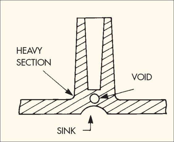
Uniform wall thickness is a major principle in the design of plastic parts. If the nominal wall thickness is not uniform, it will make the plastic melt filling speed and cooling shrinkage is not uniform, which will cause depression, vacuum bubble, warpage, and even cracking, or even lead to shrinkage marks, thermal stress, deflection part distortion, different color or different transparency.
When taking smaller wall thickness, the strength and stiffness of the product will be poor in use and assembly. From the economic point of view, too thick products not only increase the material cost but also prolong the production cycle. The thick glue area cools slower than the next thin glue area, thus creating shrinkage marks.
B. Wall thickness transition
Most of the thicker glues can be designed with reinforcement to change the total wall thickness. In addition to saving material and production costs, it can also save cooling time, which is approximately proportional to the wall.
In addition, the design of the wall thickness also takes into account the flow, i.e. the distance of the melt from the gate to each part of the cavity.
If the ratio of flow to wall thickness is too large, the place far from the gate will be short of material, which is often said to be not full. Therefore, if necessary, the wall thickness should be increased.

C. Sharp corners
Sharp corners usually result in defective parts and stress concentrations. Sharp corners often cause undesired material build-up after post-treatment processes, such as plating and painting.
Concentrated stress areas can break when subjected to load or impact, so we should avoid sharp corners when designing.
The direction of mold release and mold pulling slope
Each injection molded product should first determine its mold opening direction and parting line at the beginning of design to ensure that the core extraction mechanism is reduced as much as possible and to eliminate the impact of the parting line on appearance.
After the mold opening direction is determined, the reinforcement bars, clips, bumps, and other structures of the product should be designed to be consistent with the mold opening direction as much as possible to avoid core extraction, reduce the parting line and prolong the mold life. After the mold opening direction is determined, appropriate parting lines can be selected to improve the appearance and performance.
When the injection part is released from the molding mold movement, the release force, and the opening force are overcome. Mold opening refers to the release of the molded part shape from the mold cavity. The molded part shrinks during the cooling process and the hole wall part exerts a clamping force on the core.
Friction between the molded part and the core during mold opening, vacuum adsorption on the bottom of the hole seal during mold opening, and many reasons why the release force is much larger than the injection mold opening force.
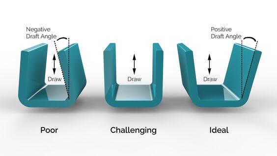
Excessive release force can cause deformation, whitening, wrinkling, and surface abrasion of the part. The slope of the mold release is a major factor in determining the size of the release force.
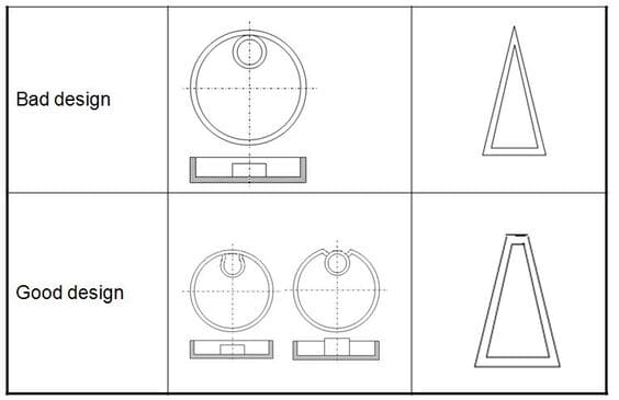
To make the product wall thickness uniform and prevent the product from attaching to the hotter concave mold after the mold is opened, the release angle should be equal for both the concave and convex mold.
However, in special cases, if the product is required to be attached to the concave die after opening, the exit angle of the adjacent concave die can be reduced appropriately, or a proper amount of backlash can be deliberately added to the concave die.
There is no definite size of the die pulling angle, but it is usually determined by empirical values. Generally speaking, highly polished outer walls can use an exit angle of 1/8° or 1/4°, while products with deep or woven patterns require a corresponding increase in the exit angle.
In addition, when considering the release slope, in principle, the larger the slope, the better for the release, but must pay attention to ensure the dimensional accuracy of the plastic parts, the size error caused by the release slope must be controlled within the range of dimensional accuracy. The shrinkage and complex shape of the plastic parts should consider a larger release angle.

The reinforcement
The strength of the plastic part does not increase completely according to its wall thickness. On the contrary, because of the increase in wall thickness caused by shrinkage and internal stress, but reduces its strength. The strength of plastic parts to the stiffness of the main, more thin-walled style combination structure, set up reinforcement in the corresponding parts to enhance the cross-sectional moment of inertia.
But after adding the reinforcement, the connection between the reinforcement and the main wall will definitely become thicker, and this thickness usually depends on the maximum circle of the inner cut, that is, depending on the thickness of the tendon and the radius of the root of the corner.

Reinforcement shrinkage parts
The thickness of the reinforcement should be minimized, but this is also limited. If the thickness of the tendon is too small it is necessary to increase the height of the tendon to increase the stiffness.
The tendon is too thin when the tendon is pressed, the tendon is easily deformed, the material is not easy to fill when forming, sticky mold, and other problems. Of course, the radius of the bottom corner of the tendon can not be too small, otherwise, it will not play a role in reducing the stress concentration.
Generally speaking, the radius of the corner of the bar root should not be less than 40% of the bar thickness, the bar thickness should be between 50% and 75% of the proper wall thickness of the base material, the high ratio is limited to small shrinkage of the material flow.
The height of the bar should be less than five times the thickness of the base material. The bars must have release angles and must be placed in the direction of the release or a movable mold assembly. The spacing between the bars must be greater than twice the thickness of the base material.
In addition, we usually want a part to be equally rigid in all directions, and the easiest way to obtain this result is to add bars to the part in both the transverse and longitudinal directions and to make them intersect vertically.
However, there is also the problem of increasing the wall thickness at the intersection, increasing the chance of shrinkage. Generally, in this case, a circular hole can be added at the intersection to create a uniform wall thickness.
The hole
In the plastic parts on the hole to make it and other parts to join or increase the combination of product function is a common method, the size, and location of the hole should try not to constitute an impact on the strength of the product or increase the complexity of production, the following are several factors to be considered when designing the hole.
1. The distance between the connected holes or the distance between the holes and the straight edges of the adjacent products should not be less than the diameter of the holes, especially the value of the edge should be as large as possible, otherwise the perforation position is prone to fracture.
If there is a thread attached to the hole, the distance between the screw hole and the edge of the product is generally greater than three times the diameter of the hole.
2. The types of holes are generally through holes, blind holes, and graded holes. From the perspective of assembly, through-holes are used more than blind holes and are easier to produce than blind holes.
From the mold design point of view, the design of a through-hole will also be more convenient in structure, which can be formed by the combination of two cores fixed on the moving mold and the fixed mold or can be formed by only one core fixed on the moving mold or the fixed mold.
The former forms two cantilever beams under the action of fluid plastic, but the force arm is short and the deformation is not large. The latter has lap joints with both moving and fixed molds and generally forms a simple support beam with little deformation.
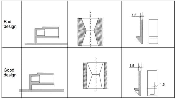
When two cores are used, the diameters of the two cores should be slightly different to avoid the product from buckling due to the slight deviation of the axis of the two side pegs, and the two ends of the joint must be ground flat.
Blind hole cores are completely cantilevered beams, which are easily bent by the impact of fluid plastic, and the formed hole will become a shaped hole. If the diameter of the blind hole is only 1.5mm or less, the depth of the blind hole should not be larger than the size of the diameter. And the bottom wall thickness of the blind hole should not be less than one-sixth of the hole diameter, otherwise, there will be shrinkage.
3. Side holes are often formed by the side core method, which will increase the cost of the mold, and if the side core is too long, it is easy to break, increasing mold maintenance costs.

Pillar
The pillar protrudes from the uniform wall thickness of the rubber and is used to assemble products, separate objects, and support other parts. Hollow pillars can be used to embed parts, tighten screws, etc.
These applications are to have sufficient strength to support the pressure without breaking. Pillars are generally made cylindrical because they are easy to mold and have good mechanical properties.
Generally speaking, the pillar should not be designed as a separate cylinder but should be connected to the outer wall or used with reinforcement as much as possible, to strengthen the pillar and to make the flow of the adhesive smoother, and the connection with the outer wall should be made into a thin-walled connection to avoid shrinkage.

The wall thickness of the pillar should be between 0.5 and 0.75 of the base material thickness, and the top hole of the pillar should be chamfered to facilitate the installation of the screw guide.
The top hole of the column should be chamfered to facilitate the installation of the screw guide. The column should have a mold pulling slope. These points are similar to the design requirements of reinforcing bars, so it can also be said that the pillar is a variation of the bar.
Snap
Snap assembly is a convenient assembly, cost-saving, green connection, because the combination of snap parts in the production of finished products at the same time molding, assembly without other locking accessories such as screws, as long as the combination of the two sides of the buckle position with each other to snap on.
The principle of the snap is to promote a part of the projection through the other part of the obstacle, in the process of promoting the elastic deformation, when through the obstacle to restoring the original state of the two together.
Interference connection
Holes and shafts are connected by interference fit to transfer torque and other functions, interference connection is more convenient and simple. The main consideration in the design process is the amount of interference, if the amount of interference is too small, the connection is not reliable, if the interference is too large, it is difficult to assemble, but also easy to break.
In the design process, the tolerance of the hole and the shaft, as well as the working temperature, should be considered, because the temperature will directly affect the size of the interference.
In most cases, the shaft is generally a metal shaft, and to ensure the reliability of the connection, knurled grooves are generally added to the mating shaft during design. The general amount of interference can be calculated by the following formula.
Y=Sd( (K+v sleeve)/E sleeve)/K
Where S is the design stress, v is Poisson’s ratio, E is the modulus of elasticity, K is the geometric coefficient, and K can be calculated by the following formula.
K = (1+(d/D)2)/(1 – (d/D)2)
The mating force can be calculated by the following formula: W = Sdlπμ/K
μ is the friction coefficient and l is the mating length.
In addition, the connection methods between plastic parts are hot riveting, welding, ultrasonic welding, etc.
The impact of tolerance
Most plastic products can achieve high precision with dimensional tolerances, while some high shrinkage and some soft materials are more difficult to control.
Therefore, the product design process is to take into account the use of the product environment, plastic materials, product shape, etc. to set the tightness of tolerances.
Because the customer’s requirements are getting higher and higher, the previous concept of fit has to be revised slowly. Fit, precision, and aesthetics are to be brought out in the product at the same time.
The higher the tolerance, the higher the quality of the product, but the higher the cost and the more time it takes to meet the requirements. the The injection molding process is generally divided into three quality levels, namely general-purpose injection molding, medium precision molding, and precision injection molding.
General-purpose injection molding process requires a low level of quality control and is characterized by low return rates and fast production cycles. Medium-precision injection molding can be more expensive because it requires higher demands on the mold and production manufacturing process, requiring frequent quality checks.
The third type, precision thin wall injection molding cycle, requires precise molds, optimal production conditions, and 100% continuous production monitoring. This affects the production cycle time and increases the unit production cost and quality control cost.
From the point of view of product quality, of course, the higher the accuracy the better, but from the point of view of economic production costs the lower the cheaper. A designer at this time must choose between the two.
Generally speaking, to meet the performance, and appearance requirements, with the requirements of the premise of appropriate relaxation of non-critical size tolerance.

The choice of materials
Generally speaking, there is no bad material, only the wrong material used in a particular area. Therefore, the designer must thoroughly understand the performance of the various materials available, and carefully test these materials to study their impact on the performance of molded and processed products with various factors.
The most commonly used in plastic injection molding manufacturing material is thermoplastic. It can be further divided into amorphous and semi-crystalline plastics. These two types of materials differ significantly in their molecular structure and properties affected by crystallization.
In general, semi-crystalline thermoplastics are mainly used for mechanically strong parts, while amorphous thermoplastics are often used for housings because they are not easily bent.
Thermoplastics are available in unreinforced, glass fiber reinforced, mineral, and vitreous-filled varieties.
Glass fibers are primarily used to increase strength, stiffness, and application temperature; minerals and glass fibers have a lower reinforcement effect and are primarily used to reduce warpage. The exact amount of change in plastic properties with the addition of reinforcements should be verified by asking the material supplier or by experimentation.
Some thermoplastic materials, particularly PA6 and PA66, are highly hygroscopic. This can have a significant impact on their mechanical properties and dimensional stability.
Some requirements are related to processing considerations and assembly. It is also important to investigate the concentration of several different functions in one part, which can save expensive assembly costs.
This guideline is very useful for calculating production costs. In the price calculation, it can be seen that not only the price of raw materials should be taken into account, but it should also be noted that materials with high performance (rigidity, toughness) can lead to thinner wall thicknesses and thus shorter production cycles. Therefore, it is important to list all the criteria and evaluate them systematically.
Rounded corners
Sharp corners usually lead to parts with defects and stress concentrations, where concentrated stresses can break when subjected to loads or impacts.
Larger rounded corners provide a solution to this drawback, not only reducing the stress concentration factor but also making the flow of plastic smoother and easier when the finished product is released from the mold. If the inner corners are rounded and the outer corners are sharp, the corners will still be thicker than the rest and shrinkage will still occur.
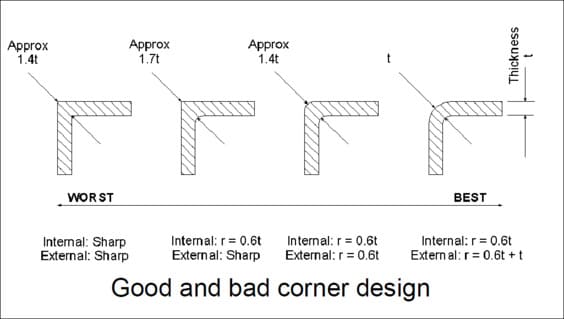
We can make the uniform wall thickness uniform by rounding both the inner and outer corners, in which case the outer corner is the sum of the inner corner plus the basic wall thickness.
The design guideline of the corner bit also applies to the overhanging beam-type fastening bit. Because this fastening method is required to bend the cantilever arm embedded, the design of the corner position illustrates that if the corner arc position R is too small will cause its stress concentration coefficient to be too large, therefore, the product is easy to break when bending, arc position R is too large, it is easy to appear shrinkage lines and hollow.
Therefore, the arc position and wall thickness are a certain ratio. Generally, between 0.2 to 0.6, the ideal value is 0.5 or so.
Conclusion
In this paper, we analyze the design points of injection molded parts from the aspects of wall thickness, draft angle, reinforcement, hole, strut, snap, interference connection, tolerance, and rounded corner.
Of course, the design of injection molded products is also limited by the environment, conditions, and requirements, so it is necessary to deal with specific situations.


