Enjeksiyon kalıplama1 seçeneklerini karşılaştıran okuyucular için bu makale; bir projenin tasarımdan tekrarlanabilir üretime geçip geçemeyeceğini belirleyen enjeksiyon kalıbı2, plastik3 malzeme davranışı, tedarikçi değerlendirmesi ve kalite kontrol kararlarını bir araya getirir.
Daha geniş bir bağlam için bu konuyu tedarikçi bulma kılavuzuyla karşılaştırın.
- Enjeksiyon Kalıplama için Nervür Tasarımında Tekdüze Cidar Kalınlığı Nasıl Elde Edilir? konusu; kalıp tasarımı, malzeme davranışı, proses kararlılığı ve kontrol kanıtları birlikte değerlendirilerek karara bağlanmalıdır.
- Düşük bir fiyat teklifi yeterli değildir; alıcılar DFM geri bildirimini, kalıp riskini, teslim süresini, doğrulama kayıtlarını ve tedarikçinin yanıt disiplinini kontrol etmelidir.
- En güvenli sonraki adım, çelik kesmeden veya üretimi onaylamadan önce zorunlu işlevsel gereksinimleri kozmetik tercihlerden ayırmaktır.
Enjeksiyon Kalıplamada Nervürler Nedir?
Şangay fabrikamızda 90T'den 1850T'ye kadar 47 enjeksiyon kalıplama makinesi çalıştırıyoruz, bu yüzden her kalıp kararını sadece fiyat teklifi değil, bir proses penceresi sorunu olarak ele alıyoruz.
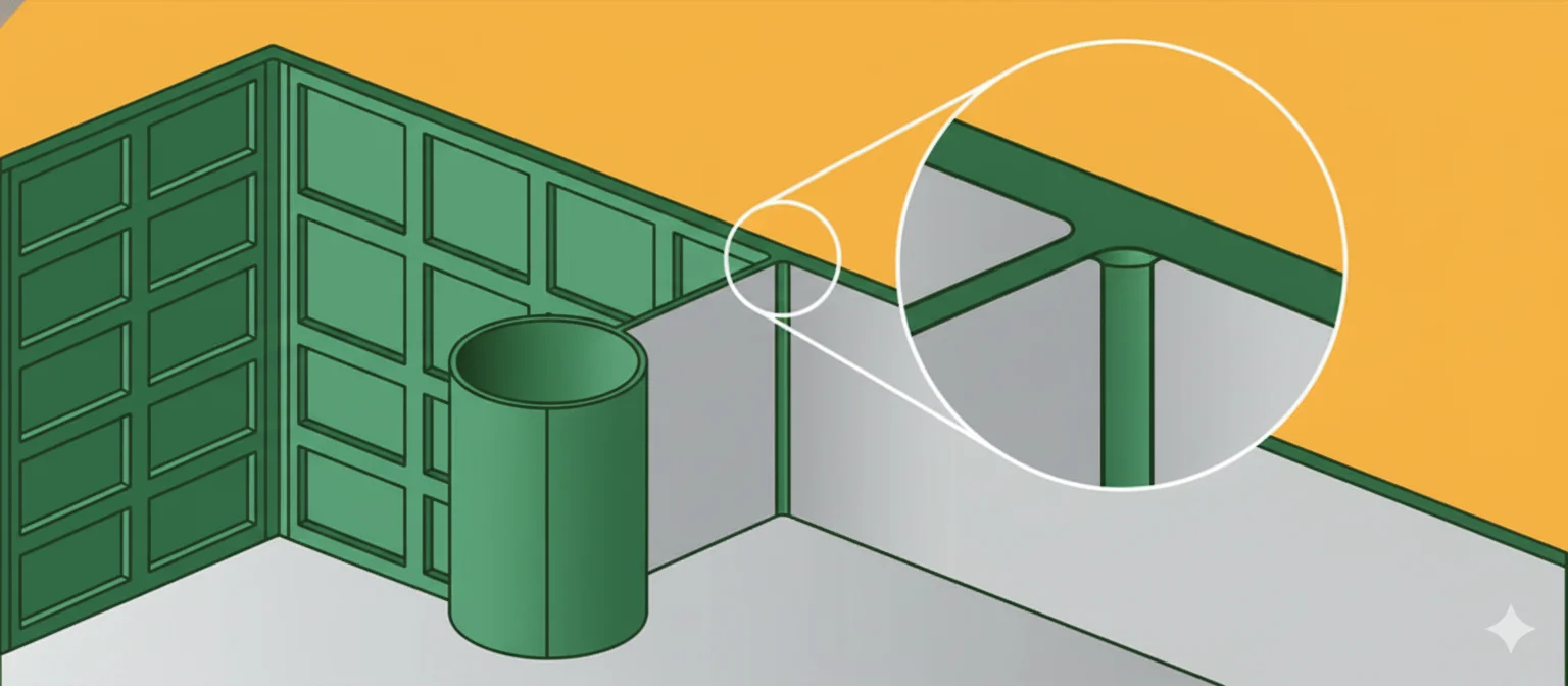
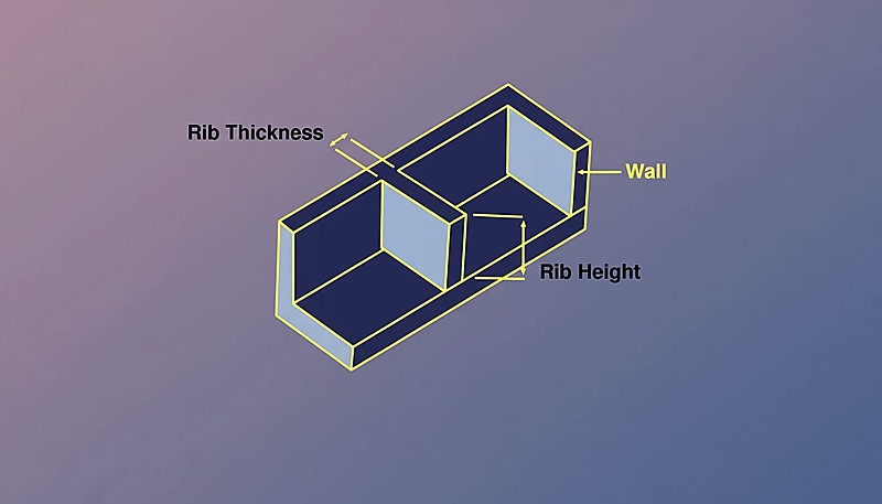
Nervürler, bir parçanın nominal duvarına dik uzanan ince, yapısal ve duvar benzeri özelliklerdir. Esas olarak genel duvar kalınlığını artırmadan kalıplanmış bir bileşenin rijitliğini ve dayanımını artırmak için kullanılırlar.
Daha geniş bir bakış için eksiksiz enjeksiyon kalıplama kılavuzumuz süreç temellerini, malzeme davranışını ve üretim kararlarını kapsar.
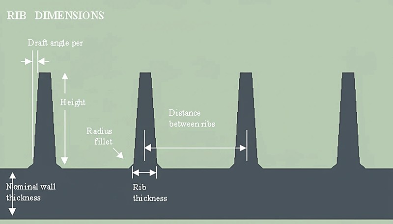
Nominal et kalınlığına göre fazla kalın bir nervür, görünen yüzeyde belirgin çökme izlerine yol açar; fazla ince bir nervür ise amaçlanan yapısal takviyeyi sağlamaz. Nervür kalınlık oranı — genellikle nominal et kalınlığının 40% ila 60%‘ı — kontrol edilmesi gereken en önemli parametredir. Tasarımcılar kalınlığın yanı sıra nervür yüksekliğini, taban radyüsünü, kalıp çıkış açısını ve aralığı da yönetmelidir; çünkü bu değişkenlerin her biri dolum basıncı, soğuma süresi ve parça çarpılmasıyla etkileşir.
Enjeksiyon Kalıplama (IM) bağlamında “eşit duvar kalınlığını” korumak, nervürün ana duvar kadar kalın olması anlamına gelmez. Bunun yerine, nervür geometrisinin kesişim noktasında (nervürün duvarla birleştiği yerde) büyük bir ısıl kütle oluşturmayacak şekilde tasarlanmasını ifade eder. Kesişimdeki kütle çok büyükse malzeme çevresindeki duvara göre eşit olmayan biçimde soğur ve bunun sonucunda Çökme İzleri veya vakum boşlukları oluşur.
Doğru nervür tasarımı, mühendislerin ağır ve dolu kesitleri daha hafif, “içi boşaltılmış” yapılarla değiştirmesine ve dayanım-ağırlık oranını optimize etmesine olanak tanır.
Nervür tabanı fazla kalın olduğunda — örneğin nominal cidarın %80’i veya daha fazlası — birleşim noktasında fazla malzeme birikir. Bu yerel kütle, ısıyı çevresindeki cidardan daha uzun süre tutarak plastiğin soğuma sırasında düzensiz çekmesine neden olur. Sonuç, karşı tarafta çökme izi olarak bilinen görünür bir çöküntüdür. Bu nedenle tasarımcılar nervür kalınlığı oranını nominal cidarın %40–60’ı ile sınırlar ve geçişin düzgün olmasını sağlamak için taban yarıçapını kontrol eder.
"Çöküntü izlerini önlemek için nervür tabanı kalınlığı, bitişik nominal cidar kalınlığının 40% ile 60%'ı arasında tutulmalıdır."True
Bu aralık T birleşiminde aşırı ısı tutulmasını önleyerek nervür ile duvarın benzer hızlarda soğumasını ve böylece yüzey estetiğinin korunmasını sağlar.
"Nervürleri ana cidarla aynı kalınlıkta yapmak, yan etki oluşturmadan parça dayanımını artırır."False
Nervür kalınlığının et kalınlığına eşit olması, düzensiz soğuma nedeniyle çöküntü izlerine, boşluklara ve uzun çevrim sürelerine yol açan kalın bir kütle bölgesi oluşturur.
Nervürler İçin Temel Tasarım Parametreleri Nelerdir?
Nervür geometrisi ile malzeme akışı arasındaki etkileşim de aynı ölçüde önemlidir. Polikarbonat gibi yüksek viskoziteli malzemeler tam dolum için daha büyük radyüsler ve daha düşük nervür yüksekliği oranları gerektirirken, polipropilen gibi düşük viskoziteli malzemeler çökme sorunu olmadan daha yüksek ve ince nervürleri kaldırabilir.
Kozmetik yüzeyi veya kalıplanabilirliği bozmadan etkili nervürleme elde etmek için belirli boyutsal parametrelere uyulmalıdır.
| Parametre | Sembol | Önerilen Değer / Aralık | Önemli Not |
|---|---|---|---|
| Nominal Duvar Kalınlığı | T | 2.0 mm – 4.0 mm (Tipik) | Ana parça geometrisinin referans kalınlığı. |
| Nervür Tabanı Kalınlığı | t değeri | T'nin %40 – %60'ı | 60%, çöküntü izi riski oluşturur. |
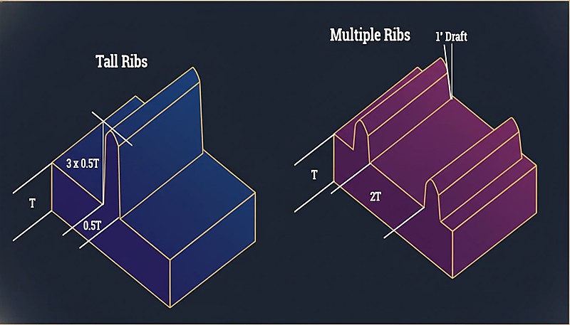
| Kaburga Yüksekliği | H | Maks. 3,0 × T | Aşırı yükseklik, yüksek enjeksiyon basıncı gerektirir ve gaz tuzaklarına neden olur. |
| Çekim Açısı | θ | Her taraf için 0.5° – 1.5° | Parçanın kalıptan ayrılması için gereklidir; uçtaki nervür kalınlığını azaltır. |
| Taban Yarıçapı | R | T'nin %25 – %50'si | Gerilim yoğunlaşmalarını azaltır; çok büyük olması çökme oluşturur. |
| Kaburga Aralığı | S | Min. 2.0 × T | Yeterli soğutmayı sağlamak için paralel nervürler arasındaki mesafe. |
| Uç Kalınlığı | t(uç) | Min. 0.75 mm | Gazı tahliye edecek ve eksik dolumu önleyecek kadar kalın olmalıdır. |
Nervürlemenin Avantajları ve Dezavantajları Nelerdir?
Nervürler rijitliği artıran yapısal unsurlardır; ancak dikkatle yönetilmesi gereken çöküntü izleri, çarpılma ve kalıp karmaşıklığı oluştururlar.
| Özellik | Açıklama | Kalıplama Prosesine Etkisi |
|---|---|---|
| Avantajlar | Malzeme Azaltma | Kullanılan reçine hacmini azaltarak parça maliyetini ve ağırlığını düşürür. |
| Çevrim Süresi Optimizasyonu | İnce kesitler kalın dolu cidarlardan hızlı soğuyarak toplam çevrimi kısaltır. | |
| Rijitlik-Ağırlık Oranı | Belirgin kütle eklemeden rijitlik için atalet momentini artırır. | |
| Dezavantajlar | Çöküntü İzi Riski | Hatalı kalınlık oranları (t > 60%T), "A-side" yüzeyinde görünür çökmelere neden olur. |
| Dolum Zorlukları | Derin ve ince nervürlerin doldurulması zor olabilir; eksik doluma veya yüksek enjeksiyon basınçlarına yol açar. | |
| Havalandırma Sorunları | Derin nervürlerin tabanındaki hava kapanları dizel etkisine (yanma) neden olabilir 2 . |
Yaygın Uygulama Senaryoları Nelerdir?
Nervürler, çeşitli sektörlerdeki yapısal plastik parçalarda yaygın olarak bulunur.
Otomotiv İç Mekânları: Akrilonitril Bütadien Stiren (ABS) veya Polipropilen (PP) kullanılan gösterge paneli alt yapıları ve kapı panelleri, fazla ağırlık oluşturmadan rijitlik sağlamak için nervürlere ihtiyaç duyar.
Tüketici Elektroniği: Dizüstü bilgisayar ve yönlendirici muhafazalarında, iç bileşenleri korumak ve ısı dağılımını yönetmek için sık nervür desenleri kullanılır.
Elektrikli El Aletleri: Cam Elyaf Dolgulu Naylondan (PA6-GF) yapılmış muhafazalarda, yüksek darbe ve tork yüklerine dayanmak için çapraz nervürler kullanılır.
Batarya Muhafazaları: Büyük muhafazalarda, uzun düz yüzeylerde çarpılmayı önlemek için nervürler gerekir.
"Nervürlerin kalıptan temiz biçimde çıkması için her tarafta en az 0.5° kalıp çıkış açısı zorunludur."True
Kalıp çıkış açıları, çıkarma sırasında çelik ile plastik arasındaki sürtünmeyi azaltarak sürüklenme izlerini ve kalıba sıkışan parçaları önler.
"Kalıp çeliğinin parlatılması, derin nervürlerde kalıp çıkış açısı ihtiyacını ortadan kaldırır."False
Parlatma yardımcı olsa da kalıptan çıkarma sırasında oluşan vakum kuvvetlerini ve sürtünmeyi ortadan kaldırmaz; kalıp açısı fiziksel olarak yine gereklidir.
Eşit Duvar Kalınlığı İçin Nervürler Nasıl Tasarlanır?
Üretim sahamızda mühendislerimiz ilk numunelerdeki her nervür/cidar oranını doğrular; çünkü nervür tabanı kalınlığındaki 0.05 mm sapma, kozmetik bir parçanın görünür yüzeyde kabulden redde geçmesine neden olabilir.
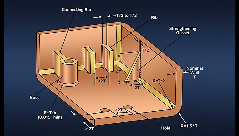
Nervür tabanını nominal et kalınlığının 40–60%‘i olarak belirleyin, yüksekliği et kalınlığının ≤ 3× değeriyle sınırlayın, her yana 0.5° çıkma açısı verin ve her taban köşesine 0.25×T yarıçap ekleyin. Her adım aşağıda ayrıntılı olarak açıklanmıştır.
Nominal Duvarı (T) Belirleyin: Ana duvar kalınlığını malzemenin akış özelliklerine göre belirleyin (ör. Polikarbonat (PC), Polietilenden (PE) daha kalın duvarlar gerektirir).
Taban Kalınlığını (t) Hesaplayın: Kozmetik yüzeylerde (yüksek parlaklık) t = 0.4 × T olarak ayarlayın. Yapısal veya dokulu yüzeylerde t = 0.6 × T olarak ayarlayın. Bu oran, karşıdaki görünür yüzeyde çökme izlerini önlemek için yerel malzeme hacmini yeterince düşük tutar.
Kalıptan Çıkma Açılarını Uygulayın: Her bir tarafa 0.5° ila 1.0° kalıptan çıkma açısı ekleyin. Not: Bu, nervür yükseldikçe kalınlığının azalmasına neden olur.
"Cam elyaf dolgulu malzemeler daha az çeker ve bazı durumlarda biraz daha kalın federlere (duvar kalınlığının %70'ine kadar) olanak verir."True
PA66-GF30 gibi malzemelerdeki elyaflar çekmeye direnerek bazen görünür çöküntü izi olmadan daha yüksek nervür-cidar oranına izin verir.
"Tüm plastik malzemeler, nervür kalınlığı ve çökme izi eğilimi açısından aynı davranır."False
Amorf plastikler (PC, ABS gibi) ile yarı kristal plastiklerin (POM, PBT gibi) çekme oranları farklıdır; bu nedenle özel nervür tasarım oranları gerekir.
Uç Kalınlığını Doğrulayın: Nervürün üst kısmındaki kalınlığı kontrol edin. Uygun hava tahliyesi ve dolum için 0.75 mm’den az olmadığından emin olun.
Taban Radyüsleri Ekleyin: Gerilme yığılmasını azaltmak için tabana 0.25 × T radyüs ekleyin. Kökte “kalın bir plastik kütlesi” oluşmasını önlemek için > 0.5 × T radyüslerden kaçının.
Nervürleri Aralıklı Yerleştirin: Birden fazla nervür gerekiyorsa aralarında en az $2 \times T$ mesafe bırakın. Nervürler birbirine çok yakınsa aralarındaki çelik takım incelir ve soğutulması zorlaşır (termal kapı).
Simülasyonu Çalıştırın: Olası çökme izlerini ve hacimsel çekmeyi kontrol etmek için Moldflow analizi kullanın.
Nervürlü Parçalar İçin RFQ Göndermeden Önce Neleri Kontrol Etmelisiniz?
RFQ öncesi temel kontroller; çizimde feder-et kalınlığı oranını, kalıp açısını ve taban yarıçapını doğrulamak ve çökme riski için DFM incelemesi istemektir.
RFQ ayrıca üretim varsayımlarını da sormalıdır. Takım çeliği, boşluk sayısı, dağıtıcı tipi, yüzey bitimi, deneme programı, ölçüm yöntemi, paketleme ve değişiklik kontrol beklentilerinin tümü nihai maliyeti ve teslimat süresini etkiler. Bu varsayımlar açık olduğunda, sonraki müzakere daha hızlı ve güvenli olur.
Güçlü bir teknik yanıt, belirsizliği gizlemek yerine eksik girdileri belirler. Tedarikçi tolerans yığılması, giriş izi sınırları, reçine sertifikası, renk eşleştirme veya yıllık talep değişimi hakkında soru soruyorsa mühendislik ekibi genellikle projeyi üretim derinliğinde değerlendiriyordur.
ZetarMold tarzı projelerde en iyi sonuç, net bir üretim yoludur: DFM incelemesi, enjeksiyon kalıbı tasarımı onayı, takım imalatı, numune alma, muayene, düzeltici faaliyet ve üretim onayı. Bu sıra, makaleye pratik bir otorite kazandırır ve alıcılara bir sonraki görüşme için yararlı bir kontrol listesi sunar.
İyi Nervür Tasarımını Hangi Üretim Kanıtları Doğrular?
En güçlü kanıt, nervür kalınlığı ile taban yarıçapının tolerans içinde olduğunu ve çöküntü izi bulunmadığını gösteren bir ilk parça raporudur.
Bir proje kozmetik veya dar toleranslı plastik parçalar içeriyorsa kanıtlar numune onay kurallarını da kapsamalıdır. Sınır numuneleri, ölçüm fikstürleri, renk standartları ve kusur tanımları; kalıp denemeden üretime geçtiğinde öznel anlaşmazlıkları azaltır.
Tedarik kararlarında en güçlü gösterge, tedarikçinin kalıp seçimlerini üretim sonuçlarıyla ilişkilendirip ilişkilendiremediğidir. Uygulamalı bir inceleme; soğutma, havalandırma, çelik seçimi, bakım erişimi ve proses izlemenin maliyeti, teslimatı ve parça kalitesini nasıl koruduğunu açıklamalıdır.
Bu kanıt öncelikli yapı, makale yalnızca genel imalat iddiaları değil somut kontroller sunduğu için okuyucuların daha iyi karar vermesine ve yanıt motorlarının sayfadan güvenle alıntı yapmasına yardımcı olur.
Nervürlü Kalıplanmış Parçalar Sipariş Edilirken Hangi Son Kontroller Riski Azaltır?
Kalıplandığı haliyle nervür ölçülerini CMM ile çizime göre karşılaştırın, ardından onaydan önce görünür yüzeyde çökme izi olup olmadığını kontrol edin.
İkinci yararlı kontrol, değişiklik yönetimidir. Enjeksiyon kalıplama projeleri; geç tasarım değişiklikleri, belirsiz toleranslar veya eksik numune kriterleri tedarikçiyi çeliği revize etmeye, denemeleri yeniden yapmaya ya da kontrolleri tekrarlamaya zorladığında genellikle pahalılaşır. Net girdiler, bir sonraki teklif veya üretim kararından önce bu riski azaltır.
Nervür Tasarımında Eşit Cidar Kalınlığı İçin Temel Çıkarımlar Nelerdir?
Nervür tasarımında eşit duvar kalınlığı elde etmek, yapısal gerekliliklerle kalıplama fiziği arasında denge kurmayı gerektirir. Mühendisler %40-60 kalınlık kuralına uyarak, yüksekliği nominal duvarın 3 katıyla sınırlayarak ve uygun kalıptan çıkma açıları uygulayarak güçlü, hafif ve çökme izi gibi kozmetik kusurlardan arınmış parçalar tasarlayabilir. Bu kısıtları göz ardı etmek, yüzey kusurları veya proses verimsizlikleri nedeniyle neredeyse kaçınılmaz biçimde redde yol açar. Kapsamlı bir genel bakış için Enjeksiyon Kalıbı Eksiksiz Kılavuzumuza bakın. Kapsamlı bir genel bakış için enjeksiyon kalıbı tasarımı sayfamıza bakın.
Enjeksiyon Kalıplama Projeniz İçin Teklif mi Gerekiyor?
ZetarMold mühendislik ekibinden rekabetçi fiyat, DFM geri bildirimi ve üretim zaman çizelgesi alın.
Ücretsiz Fiyat Teklifi İsteyin →
Nervür Tasarımı ve Duvar Kalınlığı Hakkında Başka Neler Bilmelisiniz?
Bu kısa yanıtlar; nervür oranları, malzeme seçimi ve kalite kontrolleri hakkındaki en yaygın soruları ele alır.
Sıkça Sorulan Sorular
İdeal nervür-cidar kalınlığı oranı nedir?
Çoğu termoplastikte nervür tabanı, nominal cidar kalınlığının 40–60%‘i olmalıdır. Görsel (Class A) yüzeylerde, görünen taraftaki çökme izlerini azaltmak için 40%‘e yakın kalın. Görünmeyen yapısal nervürlerde görsel sorun oluşturmadan 60%‘e yaklaşabilirsiniz. 70%‘in üzerine çıkmak, proses koşullarından bağımsız olarak karşı yüzeyde görünür çökme izini neredeyse kesinleştirir. Oran ayrıca malzemenin çekme özelliklerine bağlıdır: PP gibi yüksek çekmeli malzemeler, ABS gibi düşük çekmeli malzemelere göre daha düşük bir oran (yaklaşık 0.4×) gerektirebilir; ABS ise 0.5–0.6× oranını tolere edebilir. Kalıp yatırımından önce oranı daima Moldflow simülasyonu sonuçlarıyla doğrulayın.
Bir nervürün yüksekliği et kalınlığına göre ne kadar olmalıdır?
Kaburga yüksekliğini nominal duvar kalınlığının 3 katı veya altında tutun. Daha uzun kaburgaların tamamen dolması zordur, özellikle polikarbonat gibi yüksek viskoziteli malzemelerle, ve kalıptan çıkarma sırasında eğilme veya kırılma eğilimi gösterirler. Tek bir kaburganın sağlayabileceğinden daha fazla sertlik gerekiyorsa, bir uzun kaburga yerine, aralarında en az duvar kalınlığının 2 katı mesafe olan birden fazla kısa kaburga kullanın. Bu paralel kaburga yaklaşımı yükü daha eşit dağıtır ve kalıp dolumunu öngörülebilir kılar. Pratikte, mühendislerimiz genellikle duvar kalınlığının 2 katı bir yükseklikle başlar ve ancak simülasyon kaburga ucuna hava kalmadan akış cephesinin ulaştığını doğruladığında artırır.
Kaburga pah açısı duvar kalınlığını etkiler mi?
Evet. Pah açısı (tipik olak yan başına 0.5° ila 1.0°) kaburga kesitini tabandan uca doğru azaltır. Yan başına 1.0° pah açısına sahip bir kaburga, yüksekliğin her mm’si için kabaca her yanda 0.035 mm kaybeder, bu da 6 mm yüksekliğindeki bir kaburganın toplamda yaklaşık 0.42 mm daraldığı anlamına gelir. Kaburganın kısa dolma olmadan tamamen dolduğundan emin olmak için uç kalınlığının her zaman 0.75 mm üzerinde kaldığını doğrulayın. Yüksek pah açısına sahip derin kaburgalar için uç çok ince hale gelebilir—bu durumda ya pah açısını azaltırsınız (çıkarma zorluğunu artırarak) ya da daha kalın bir taban kabul eder ve çökme izlerini kapı yerleşimi ve paketleme basıncı ile yönetirsiniz.
Kaburgaların yakınında oluşan çökme izlerine ne sebep olur ve nasıl önlenir?
Çökme izleri, kaburga tabanı nominal duvara göre çok kalın olduğunda, aşırı malzemenin birikmesine ve kaburga-duvar birleşiminde düzensiz büzülmeye neden olduğunda oluşur. Lokal hacimsel büzülme, görünür yüzeyi içe doğru çeker ve görünür bir çöküntü oluşturur. Önleme, kozmetik yüzeyler için kaburga-duvar oranını 0.5 kat veya altında tutarak başlar. Gerilim yoğunluğunu azaltmak için duvar kalınlığının 0.25 katı bir taban radüsü ekleyin, ancak duvar kalınlığının 0.5 katından büyük radüslerden kaçının—bunlar kütle ekler ve çökmeyi kötüleştirir. Çelik kesmeden önce hacimsel büzülmeyi doğrulamak için Moldflow simülasyonu kullanın ve kalın kesitte paketleme basıncını iyileştirmek için kaburga yakınına kapı yerleşimini düşünün.
Kaburga tasarımında taban radüsü neden önemlidir?
Nominal duvar kalınlığının 0.25 katı bir taban radüsü, kaburga-duvar birleşimindeki gerilim yoğunluğunu azaltır, bu da darbe veya döngüsel yüke maruz kalan parçalar için kritiktir. Radüs olmadan, keskin köşe bir gerilim yükseltici görevi görür ve servis sırasında çatlak başlatabilir. Ancak, radüs kontrol edilmelidir: duvar kalınlığının 0.5 katının üzerine çıkmak birleşimde çok fazla malzeme ekler, lokal kütleyi artırır ve çökme izlerini kötüleştirir. Radüs ayrıca dolum sırasında malzemenin kaburgaya akışını iyileştirir, uçta kısa dolma şansını azaltır. Kalıp uygulamamızda, taban radüsü ilk numune örneklerinde doğruladığımız ilk ölçülerden biridir çünkü hem kozmetik kaliteyi hem de yapısal performansı doğrudan etkiler.
enjeksiyon kalıplama: Enjeksiyon kalıplama; plastiği eriten, kalıp boşluğuna enjekte eden, parçayı soğutan ve kararlı seri üretim için çevrimi tekrarlayan üretim prosesidir. ↩
enjeksiyon kalıbı: Enjeksiyon kalıbı; parça geometrisini, soğutma davranışını, itme işlemini, yolluk girişini, yüzey kalitesini ve tekrarlanabilirliği belirleyen hassas takımdır. ↩
plastik: Plastik; akışı, çekmesi, mukavemeti, ısı direnci, kozmetik kalitesi, çevrim süresi ve uzun vadeli performansı kalıplama kararlarını şekillendiren bir malzeme ailesidir. ↩