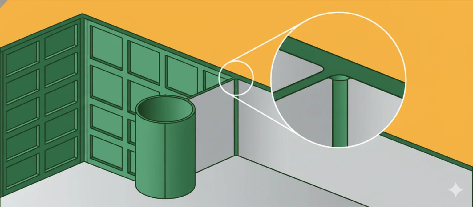
Pour les lecteurs qui comparent les possibilités de moulage par injection1, cet article établit le lien entre le moule d’injection2, le comportement du matériau plastique3, l’évaluation des fournisseurs et les décisions de contrôle qualité qui déterminent si un projet peut passer de la conception à une production reproductible.
Pour élargir le contexte, comparez ce sujet avec notre guide de sélection des fournisseurs.
- L’obtention d’une épaisseur uniforme dans la conception des nervures d’injection doit être évaluée conjointement selon le moule, le comportement matière, la stabilité du procédé et les preuves de contrôle.
- Un devis bas ne suffit pas ; les acheteurs doivent vérifier les retours de l'analyse de fabrication, les risques d'outillage, les délais de livraison, les dossiers de validation et la discipline de réponse du fournisseur.
- L'étape suivante la plus sûre consiste à séparer les exigences fonctionnelles indispensables des préférences esthétiques avant de couper l'acier ou d'approuver la production.
Que sont les nervures en moulage par injection ?
Dans notre usine de Shanghai, nous exploitons 47 machines de moulage par injection de 90T à 1850T, donc nous considérons chaque décision de fabrication d'outillage comme une question de fenêtre de processus, pas seulement un prix.
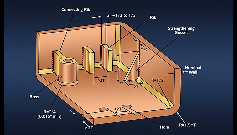
Les nervures sont des éléments structurels minces, semblables à des parois, qui s’étendent perpendiculairement à la paroi nominale d’une pièce. Elles servent principalement à accroître la rigidité et la résistance d’un composant moulé sans augmenter l’épaisseur globale de la paroi.
Pour une vue plus large, notre guide complet du moulage par injection présente les principes fondamentaux du procédé, le comportement des matériaux et les décisions de production.
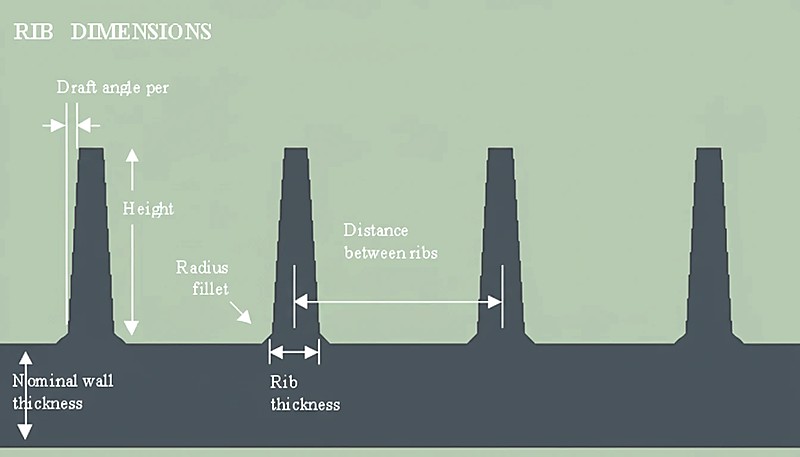
Une nervure trop épaisse par rapport à la paroi nominale provoque des retassures visibles sur la face d’aspect ; une nervure trop mince n’assure pas le renfort structurel prévu. Le rapport d’épaisseur de la nervure — généralement 40% à 60% de la paroi nominale — est le paramètre le plus important à maîtriser. Au-delà de l’épaisseur, les concepteurs doivent également gérer la hauteur de nervure, le rayon au pied, l’angle de dépouille et l’espacement, car chacune de ces variables interagit avec la pression de remplissage, le temps de refroidissement et le gauchissement de la pièce.
Dans le contexte du moulage par injection (IM), maintenir une « épaisseur de paroi uniforme » ne signifie pas que la nervure doit être aussi épaisse que la paroi principale. Il s’agit plutôt de concevoir la géométrie de la nervure de sorte que le point de jonction (où elle rejoint la paroi) ne forme pas une masse thermique importante. Si la masse à cette jonction est excessive, la matière refroidit de façon inégale par rapport à la paroi environnante, ce qui provoque des retassures ou des vides sous vide.
Une conception appropriée des nervures permet de remplacer les sections pleines et lourdes par des structures allégées et “évidées”, optimisant ainsi le rapport résistance-poids.
Lorsque la base d’une nervure est trop épaisse—80% ou plus de la paroi nominale—l’excès de matière s’accumule à la jonction. Cette masse localisée conserve la chaleur plus longtemps, entraînant un retrait irrégulier au refroidissement. Il en résulte une dépression visible sur la face opposée, appelée retassure. Les concepteurs limitent donc l’épaisseur de la nervure à 40–60% de la paroi nominale et maîtrisent le rayon de base pour adoucir la transition.
"L’épaisseur à la base d’une nervure doit rester comprise entre 40% et 60% de l’épaisseur nominale de la paroi adjacente afin d’éviter les retassures."True
Cette plage évite une rétention excessive de chaleur à la jonction en T, permet à la nervure et à la paroi de refroidir à des vitesses similaires et préserve ainsi l’aspect de la surface.
"Donner aux nervures la même épaisseur que la paroi principale renforce la pièce sans effet secondaire."False
Donner aux nervures la même épaisseur que la paroi crée une zone de forte masse qui provoque des retassures, des vides et des temps de cycle prolongés en raison d’un refroidissement irrégulier.
Quels sont les principaux paramètres de conception des nervures ?
L’interaction entre la géométrie des nervures et l’écoulement de la matière est tout aussi importante. Les matériaux très visqueux comme le polycarbonate exigent des rayons plus généreux et un rapport de hauteur de nervure plus faible pour se remplir complètement, tandis que les matériaux fluides comme le polypropylène tolèrent des nervures plus hautes et minces sans retassure.
Pour obtenir un nervurage efficace sans compromettre la surface esthétique ni la moulabilité, il faut respecter des paramètres dimensionnels précis.
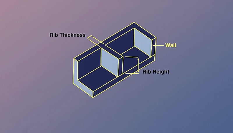
| Paramètres | Symbole | Valeur/plage recommandée | Remarque importante |
|---|---|---|---|
| Épaisseur nominale de paroi | T | 2.0 mm – 4.0 mm (type) | L’épaisseur de référence de la géométrie principale de la pièce. |
| Épaisseur à la base de la nervure | variable t | 40% – 60% de T | 60% entraîne un risque de retassures. |
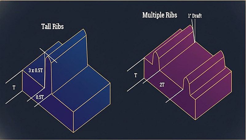
| Hauteur des côtes | H | Maximum 3.0 × T | Une hauteur excessive exige une pression d’injection élevée et provoque des poches de gaz. |
| Angle de tirant d'eau | θ | 0.5° – 1.5° par côté | Essentielle au démoulage de la pièce ; réduit l’épaisseur de la nervure à son extrémité. |
| Rayon de la base | R | 25% – 50% de T | Réduit les concentrations de contraintes ; une taille excessive crée des retassures. |
| Espacement des nervures | S | Min. 2.0 × T | Distance entre nervures parallèles assurant un refroidissement adéquat. |
| Épaisseur de la pointe | t(pointe) | Minimum 0.75 mm | Doit être suffisamment épais pour évacuer les gaz et éviter les remplissages incomplets. |
Quels sont les avantages et les inconvénients des nervures ?
Les nervures augmentent la rigidité mais introduisent retassures, gauchissement et complexité d’outillage, qu’il faut maîtriser.
| Fonctionnalité | Descriptif | Incidence sur le procédé de moulage |
|---|---|---|
| Avantages | Réduction de matière | Réduit le volume de résine utilisé, diminuant ainsi le coût et le poids de la pièce. |
| Optimisation du temps de cycle | Les sections minces refroidissent plus vite que les parois pleines épaisses, ce qui réduit la durée totale du cycle. | |
| Rapport rigidité-poids | Augmente le moment d’inertie pour améliorer la rigidité sans ajouter une masse importante. | |
| Inconvénients | Risque de retassures | Des rapports d’épaisseur incorrects (t > 60%T) provoquent des creux visibles sur la surface « face A ». |
| Difficultés de remplissage | Les nervures profondes et minces peuvent être difficiles à remplir, entraînant des remplissages incomplets ou des pressions d’injection élevées. | |
| Problèmes de mise à l’air | Les poches d’air au fond des nervures profondes peuvent provoquer un effet diesel (brûlure) 2 . |
Quels sont les scénarios d’application courants ?
Les nervures sont omniprésentes dans les pièces plastiques structurelles de divers secteurs.
Habitacles automobiles : les sous-structures de tableaux de bord et les panneaux de porte en acrylonitrile butadiène styrène (ABS) ou en polypropylène (PP) ont besoin de nervures pour offrir de la rigidité sans alourdir l’ensemble.
Électronique grand public : les boîtiers d’ordinateurs portables et de routeurs utilisent des réseaux denses de nervures pour protéger les composants internes et gérer la dissipation thermique.
Outils électriques : les carters en nylon chargé de fibres de verre (PA6-GF) utilisent des nervures croisées pour résister aux chocs importants et aux couples élevés.
Boîtiers de batteries : les grands boîtiers nécessitent des nervures pour éviter le gauchissement des longues surfaces planes.
"L'application d'un angle de dépouille d'au moins 0.5° par côté est obligatoire pour que les nervures soient correctement éjectées du moule."True
Les angles de dépouille réduisent le frottement entre l’acier et le plastique lors de l’éjection, évitant ainsi les marques de traînée et le coincement des pièces.
"Le polissage de l’acier du moule élimine le besoin d’angles de dépouille sur les nervures profondes."False
Bien que le polissage soit utile, il n’élimine pas les forces de vide et le frottement générés lors de l’éjection ; une dépouille reste physiquement nécessaire.
Comment concevoir des nervures pour obtenir une épaisseur de paroi uniforme ?
Dans notre atelier de production, nos ingénieurs vérifient chaque rapport nervure/paroi sur les échantillons de premier article, car un écart de 0.05 mm sur l’épaisseur à la base de la nervure peut faire passer une pièce esthétique de l’état acceptable au rebut sur la face visible.
Fixez la base de la nervure à 40–60% de la paroi nominale, limitez sa hauteur à ≤ 3× l’épaisseur de paroi, ajoutez une dépouille de 0.5° par côté et appliquez un rayon de 0.25×T à chaque angle de base. Chaque étape est détaillée ci-dessous.
Déterminer la paroi nominale (T) : établissez l’épaisseur de la paroi principale en fonction des propriétés d’écoulement du matériau (par exemple, le polycarbonate (PC) exige des parois plus épaisses que le polyéthylène (PE)).
Calculer l’épaisseur à la base (t) : pour les surfaces d’aspect (brillant élevé), définir t = 0.4 × T. Pour les surfaces structurelles ou texturées, définir t = 0.6 × T. Ce rapport maintient le volume local de matière suffisamment faible pour éviter les retassures sur la face visible opposée.
Appliquer les angles de dépouille : ajouter une dépouille de 0.5° à 1.0° par côté. Remarque : l’épaisseur de la nervure diminuera à mesure que sa hauteur augmente.
"Les matériaux chargés de verre se rétractent moins, ce qui autorise parfois des nervures légèrement plus épaisses (jusqu'à 70% de l'épaisseur de paroi)."True
Les fibres des matériaux comme le PA66-GF30 s’opposent au retrait, ce qui permet parfois un rapport nervure/paroi supérieur sans retassures visibles.
"Tous les matériaux plastiques se comportent de la même manière en ce qui concerne l’épaisseur des nervures et la sensibilité aux retassures."False
Les plastiques amorphes (comme le PC et l’ABS) et les plastiques semi-cristallins (comme le POM et le PBT) présentent des taux de retrait différents, ce qui exige des proportions de nervures adaptées.
Vérifier l’épaisseur au sommet : contrôler l’épaisseur en haut de la nervure. Veiller à ce qu’elle ne soit pas inférieure à 0.75 mm afin de permettre un remplissage et un dégazage corrects.
Ajouter des congés à la base : prévoir un rayon de 0.25 × T à la base pour réduire la concentration des contraintes. Éviter les rayons > 0.5 × T afin de ne pas créer une « masse épaisse » de plastique au pied.
Espacer les nervures : si plusieurs nervures sont nécessaires, les espacer d’au moins $2 \times T$. Si elles sont trop proches, l’acier de l’outillage qui les sépare devient mince et difficile à refroidir (barrière thermique).
Effectuer une simulation : utiliser une analyse Moldflow pour rechercher d’éventuelles retassures et le retrait volumique.
Que faut-il vérifier avant d’envoyer une RFQ pour des pièces nervurées ?
Les contrôles essentiels avant RFQ consistent à confirmer sur le plan le rapport nervure-paroi, l’angle de dépouille et le rayon à la base, ainsi qu’à demander une analyse DFM du risque de retassure.
L’appel d’offres doit également demander les hypothèses de fabrication. L’acier de l’outillage, le nombre d’empreintes, le type de canaux, l’état de surface, le calendrier des essais, la méthode de mesure, l’emballage et les exigences de gestion des modifications influent tous sur le coût final et le délai. Lorsque ces hypothèses sont explicites, la négociation ultérieure devient plus rapide et plus sûre.
Une réponse technique solide identifiera les données manquantes au lieu de masquer l’incertitude. Si le fournisseur pose des questions sur le cumul des tolérances, les limites des vestiges de seuil, la certification de la résine, la correspondance des couleurs ou les variations de la demande annuelle, cela signifie généralement que l’équipe d’ingénierie évalue le projet en profondeur pour la production.
Pour les projets de type ZetarMold, le meilleur résultat repose sur un parcours de fabrication clair : revue DFM, validation de la conception du moule d’injection, fabrication de l’outillage, échantillonnage, inspection, actions correctives et autorisation de production. Cette séquence confère à l’article une portée pratique et fournit aux acheteurs une liste de contrôle utile pour leur prochain échange.
Quelles preuves de production démontrent une bonne conception des nervures ?
La preuve la plus solide est un rapport de premier article montrant que l’épaisseur de la nervure et le rayon à sa base sont dans les tolérances, sans retassures.
Lorsqu’un projet porte sur des pièces plastiques esthétiques ou à tolérances serrées, les preuves doivent également inclure les règles d’approbation des échantillons. Des échantillons limites, des montages de mesure, des normes de couleur et des définitions de défauts réduisent les désaccords subjectifs après le passage du moule des essais à la production.
Pour les décisions d’approvisionnement, le signal le plus probant est la capacité du fournisseur à relier les choix d’outillage aux résultats de production. Une revue pratique doit expliquer comment le refroidissement, la mise à l’air, le choix de l’acier, l’accès pour la maintenance et la surveillance du procédé protègent les coûts, les délais et la qualité des pièces.
Cette structure fondée sur des preuves aide les lecteurs à prendre de meilleures décisions et permet aux moteurs de réponse de citer la page avec confiance, car l’article fournit des contrôles concrets et pas seulement des affirmations générales sur la fabrication.
Quels contrôles finaux réduisent les risques lors de la commande de pièces moulées nervurées ?
Comparez par CMM les dimensions des nervures moulées au plan, puis contrôlez la face visible pour détecter les retassures avant approbation.
Le contrôle des modifications est une deuxième vérification utile. Les projets de moulage par injection deviennent souvent coûteux lorsque des changements tardifs de conception, des tolérances imprécises ou des critères d’échantillonnage manquants obligent le fournisseur à reprendre l’acier, à refaire les essais ou à répéter les contrôles. Des données d’entrée claires réduisent ce risque avant le prochain devis ou la prochaine décision de production.
Quels sont les points clés pour une épaisseur de paroi uniforme dans la conception des nervures ?
Obtenir une épaisseur de paroi uniforme dans la conception des nervures exige de trouver un équilibre entre les besoins structurels et la physique du moulage. En respectant la règle d’épaisseur de 40-60%, en limitant la hauteur à 3x la paroi nominale et en appliquant des angles de dépouille adaptés, les ingénieurs peuvent concevoir des pièces robustes, légères et exemptes de défauts d’aspect tels que les retassures. Le non-respect de ces contraintes conduit presque toujours à un rejet pour défauts de surface ou inefficacité du procédé. Consultez notre guide complet du moule d’injection pour une vue d’ensemble. Consultez notre conception de moule d’injection pour une vue d’ensemble.
Besoin d’un devis pour votre projet de moulage par injection ?
Obtenez des prix compétitifs, un retour DFM et un calendrier de production auprès de l’équipe d’ingénierie de ZetarMold.
Demandez un devis gratuit →
Que faut-il savoir d’autre sur la conception des nervures et l’épaisseur des parois ?
Ces réponses rapides traitent les questions les plus courantes sur les rapports de nervures, le choix des matériaux et les contrôles qualité.
Questions fréquemment posées
Quel est le rapport idéal entre épaisseur de nervure et de paroi?
Pour la plupart des thermoplastiques, la base de la nervure doit représenter 40–60% de l’épaisseur nominale de la paroi. Pour les surfaces esthétiques (classe A), restez proche de 40% afin de minimiser les retassures sur la face visible. Pour les nervures structurelles non visibles, vous pouvez approcher 60% sans pénalité esthétique. Dépasser 70% garantit presque l’apparition d’une retassure visible sur la face opposée, quelles que soient les conditions de transformation. Le rapport dépend également des caractéristiques de retrait du matériau : les matériaux à fort retrait comme PP peuvent nécessiter un rapport inférieur (environ 0.4×) à celui des matériaux à faible retrait comme ABS (qui peut tolérer 0.5–0.6×). Vérifiez toujours ce rapport par rapport aux résultats de simulation Moldflow avant de lancer l’outillage.
Quelle hauteur de nervure faut-il prévoir par rapport à l’épaisseur de paroi ?
Limitez la hauteur des nervures à 3× l’épaisseur nominale de paroi. Les nervures plus hautes sont difficiles à remplir complètement, surtout avec des matériaux très visqueux comme le polycarbonate, et ont tendance à se déformer ou à casser lors de l’éjection. Si une seule nervure n’apporte pas assez de rigidité, utilisez plusieurs nervures plus courtes, espacées d’au moins 2× l’épaisseur de paroi, plutôt qu’une nervure haute. Cette disposition parallèle répartit mieux la charge et rend le remplissage du moule prévisible. En pratique, nos ingénieurs commencent souvent par une hauteur de 2× la paroi et ne l’augmentent que si la simulation confirme que le front d’écoulement atteint le sommet sans emprisonner d’air.
L’angle de dépouille des nervures affecte-t-il l’épaisseur de paroi ?
Oui. L’angle de dépouille (généralement 0.5° à 1.0° par côté) réduit la section de la nervure de la base au sommet. Avec une dépouille de 1.0° par côté, une nervure perd environ 0.035 mm par mm de hauteur sur chaque côté ; une nervure haute de 6 mm se rétrécit donc d’environ 0.42 mm au total. Vérifiez toujours que l’épaisseur au sommet reste supérieure à 0.75 mm afin que la nervure se remplisse entièrement sans manque. Pour les nervures profondes à forte dépouille, le sommet peut devenir trop mince — il faut alors réduire l’angle de dépouille, au prix d’une éjection plus difficile, ou accepter une base plus épaisse et maîtriser les retassures par le placement du seuil et la pression de maintien.
Quelles sont les causes des retassures près des nervures et comment les éviter ?
Les retassures apparaissent lorsque la base de la nervure est trop épaisse par rapport à la paroi nominale, ce qui entraîne une accumulation excessive de matière et un retrait irrégulier à la jonction nervure-paroi. Le retrait volumique localisé tire la surface visible vers l’intérieur et crée un creux apparent. Pour les surfaces d’aspect, la prévention commence par le maintien du rapport nervure-paroi à 0.5× ou moins. Ajoutez à la base un rayon égal à 0.25× l’épaisseur de paroi pour réduire la concentration des contraintes, mais évitez les rayons supérieurs à 0.5× la paroi—ils ajoutent de la masse et aggravent les retassures. Utilisez une simulation Moldflow pour vérifier le retrait volumique avant l’usinage de l’acier et envisagez de placer le seuil près de la nervure afin d’améliorer la pression de maintien dans la section épaisse.
Pourquoi le rayon de base est-il important dans la conception des nervures ?
Un rayon de base de 0,25× l’épaisseur nominale de paroi réduit la concentration de contraintes à la jonction nervure-paroi, ce qui est crucial pour les pièces soumises à des chocs ou à des charges cycliques. Sans rayon, l’angle vif agit comme un concentrateur de contraintes et peut initier des fissures en service. Cependant, le rayon doit être contrôlé : dépasser 0,5× l’épaisseur de paroi ajoute trop de matière à la jonction, augmentant la masse locale et aggravant les marques de retassure. Le rayon améliore également l’écoulement de la matière dans la nervure pendant le remplissage, réduisant le risque de manque de matière à l’extrémité. Dans notre pratique d’outillage, le rayon de base est l’une des premières dimensions que nous vérifions sur les échantillons de première série car il affecte directement à la fois la qualité esthétique et les performances structurelles.
moulage par injection : le moulage par injection est le procédé de production qui consiste à faire fondre le plastique, à l’injecter dans l’empreinte d’un moule, à refroidir la pièce puis à répéter le cycle pour assurer une production en série stable. ↩
moule d’injection : un moule d’injection est l’outillage de précision qui détermine la géométrie de la pièce, le comportement du refroidissement, l’éjection, l’alimentation, l’état de surface et la répétabilité. ↩
plastique : le plastique désigne une famille de matériaux dont l’écoulement, le retrait, la résistance mécanique et thermique, la qualité d’aspect, le temps de cycle et les performances à long terme orientent les décisions de moulage. ↩