 Saltar para o conteúdo

Qualquer localização na peça
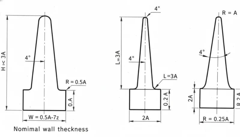
– Draft angles of 1–3° on all vertical surfaces are non-negotiable for reliable part ejection and tool longevity
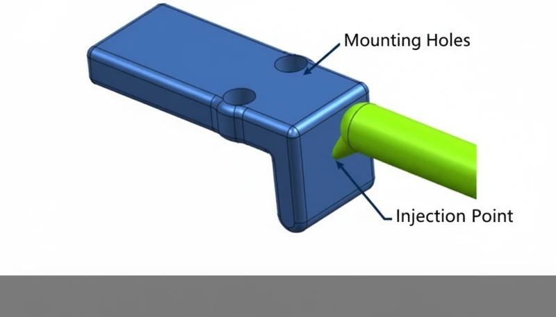
– Gate location and runner design fundamentally determine how the mold fills, packs, and how residual stress distributes in the finished part
– Design for manufacturability (DFM) review before tooling cuts can eliminate 80–90% of mold modifications, saving weeks and thousands in engineering costs
Why Does Wall Thickness Uniformity Matter So Much in Injection Molded Part Design?
Wall thickness uniformity is the foundational principle of injection molded part design, and it affects virtually every quality metric from surface appearance to dimensional stability to mechanical performance. Molten plastic flows from thick sections to thin sections and cools faster in thin areas than thick ones. Where thick and thin walls meet, the thick section continues to shrink after the thin section has solidified, pulling material inward and creating sink marks on opposite surfaces. In our factory, we see more tooling modification requests caused by wall thickness variation than any other single design issue—it is consistently the most expensive mistake to fix after tooling is cut.
The general rule is to keep wall thickness variation within ±25% of the nominal wall, and to transition between different wall thicknesses gradually over a distance of at least 3× the wall thickness difference. For most engineering thermoplastics, nominal wall thickness falls between 1.5 mm and 4 mm—thin enough to cool quickly and prevent sink, thick enough to fill reliably without excessive injection pressure. Material selection influences the optimal wall: polypropylene flows readily at 1.5 mm, while glass-filled nylon may require 2.5 mm to fill complex geometries. The table below summarizes recommended wall thickness ranges by material:
| Material | Minimum Wall | Recommended Nominal | Maximum (before sink risk) |
|---|---|---|---|
| Polipropileno (PP) | 0.8 mm | 1.5–2.5 mm | 4.0 mm |
| ABS | 1.0 mm | 2.0–3.0 mm | 4.5 mm |
| Policarbonato (PC) | 1.0 mm | 2.5–4.0 mm | 5.0 mm |
| Glass-Filled Nylon | 1.5 mm | 2.5–4.0 mm | 6.0 mm |
| TPE/TPU | 0,5 mm | 1.0–3.0 mm | 6.0 mm |
How Should Draft Angles Be Applied to Injection Molded Part Geometry?
Draft angles—small tapers applied to vertical surfaces parallel to the mold’s parting direction—are essential for reliable part ejection. Without draft, parts can stick in the cavity or core, bending ejector pins, galling tool surfaces, and producing parts that require excessive force to remove. In our experience, even a single surface without adequate draft on a textured or polished tool can cause enough friction during ejection to damage several parts per shift—damage that accumulates into thousands of scrapped parts over a production run. The ângulo de inclinação1 required depends on surface texture: smooth, polished surfaces need a minimum of 0.5–1°, lightly textured surfaces need 1.5–2°, and deeply textured surfaces (leather grain, for example) typically require 3–5° to release cleanly.
Draft analysis should be performed on every part model before tooling begins. Most CAD systems include draft analysis tools that color-map surfaces by draft angle, clearly showing under-drafted areas that will cause ejection problems. We perform this analysis as part of our standard DFM review and provide annotated part models showing every surface with insufficient draft. Addressing these issues in CAD takes hours; addressing them in cut steel takes days and costs thousands.
“Adding ribs to an injection molded part always increases its strength without any design trade-offs.”Falso
Ribs increase stiffness but must be designed carefully to avoid sink marks on the opposite surface. The standard guideline is to size ribs at 50–60% of the adjacent wall thickness. Over-thick ribs create localized mass concentrations that cool slowly, pulling material from the nominal surface and creating visible sink marks on cosmetic surfaces. Rib design is a balance between structural benefit and cosmetic impact.
“DFM review before tooling cuts can eliminate 80–90% of costly mold modifications.”Verdadeiro
Our data consistently shows that part designs reviewed by injection molding engineers before tooling begins require an average of 0.8 modifications, while designs submitted without DFM review average 4–6 modifications. Each modification adds $1,000–$10,000 in tooling cost and 1–4 weeks of schedule delay. Early DFM review is the highest-ROI activity in any injection molding program.
What Gate Design Principles Maximize Part Quality and Production Efficiency?
Gate design determines where molten plastic enters the mold cavity and how the fill pattern develops. A well-designed gate fills the cavity from the thickest section to the thinnest, allows uniform packing pressure throughout the part, places the weld line away from stress-bearing features, and locates the gate mark where it can be hidden or is cosmetically acceptable. A poorly designed gate does the opposite: it creates short shots, weak weld lines in critical areas, and forces visible gate marks onto cosmetic surfaces. In our DFM process, gate placement is always one of the first decisions we make—it constrains everything else.
Hot runner systems2 eliminate the cold runner (the solidified plastic in the feed channels) that must be removed, recycled, or discarded with each cycle. For high-volume production, hot runners pay back their additional tooling cost within months through material savings alone. We recommend hot runners for any production exceeding 100,000 annual cycles on engineering materials—the combination of material savings, reduced cycle time, and improved part quality more than justifies the $5,000–$20,000 hot runner system investment.
| Tipo de porta | Melhor para | Vantagens | Limitations |
|---|---|---|---|
| Edge (Tab) Gate | Flat parts, plaques | Simple, easy to modify | Visible mark, manual trimming |
| Porta submarina | Parts needing auto-degating | Auto-trims on ejection | Limited flow rate |
| Porta de pinos | Three-plate molds | Any location on part | Projete Peças Moldadas por Injeção para Máxima Eficiência | ZetarMold |
| Hot Tip Gate | High-volume, small parts | No runner waste, fast cycle | Hot runner system cost |
| Valve Gate | Large or cosmetic parts | Clean gate mark, no stringing | Highest hot runner cost |
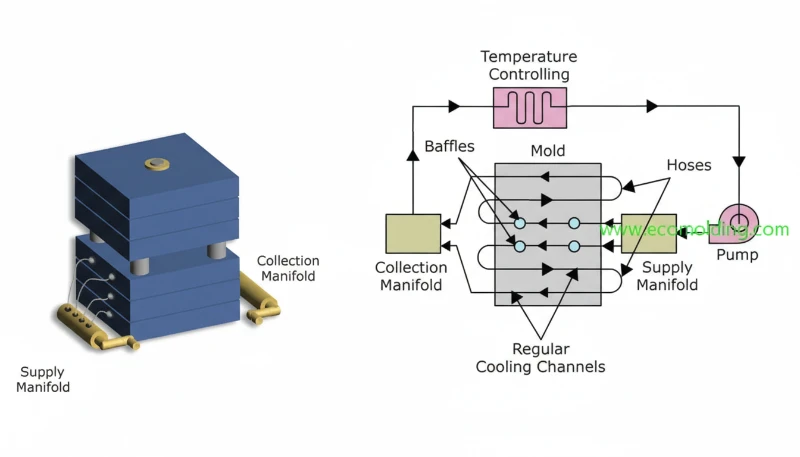
How Do Cooling System Design and Cycle Time Relate to Part Performance?
Cooling accounts for 60–75% of a typical injection molding cycle time, making it the largest single opportunity for cycle time reduction. But cooling isn’t just a speed issue—inadequate or non-uniform cooling causes warpage, residual stress, and dimensional variation that directly affect part performance. In our factory, we use mold flow simulation during the tool design phase to predict temperature gradients through the steel and identify hot spots where insufficient cooling will cause extended cycle times and part distortion. Conformal cooling channels—produced by additive manufacturing—can reach areas that conventional drilled channels cannot, reducing hot spots and enabling 20–40% cycle time reductions on complex geometries.
The part design itself influences cooling efficiency. Uniform wall thickness—already identified as the primary design principle—also optimizes cooling: uniform walls cool uniformly, enabling shorter cycles and lower residual stress. Thick sections not only cool slowly but create temperature gradients that drive differential shrinkage and warpage. We routinely perform Moldflow3 simulation for all complex parts to validate cooling design before tooling is ordered.
“Faster cooling always results in better part quality in injection molding.”Falso
Cooling rate must be balanced, not simply maximized. Cooling too rapidly can lock in high residual stress, cause surface cracking in brittle materials, and prevent crystalline polymers from reaching their optimal microstructure. The goal is uniform, controlled cooling that achieves dimensional stability and appropriate material microstructure within the minimum time—not the shortest possible cooling time regardless of consequences.
“Mold flow simulation can identify fill, weld line, and cooling problems before any tooling is cut.”Verdadeiro
Modern mold flow simulation software accurately predicts fill patterns, weld line locations, air traps, cooling time, warpage, and fiber orientation in filled materials. Addressing these issues in simulation—at essentially zero cost—versus in cut steel saves an average of $3,000–$15,000 per tool in modification costs and 2–6 weeks of schedule time. We mandate simulation for all tools over $10,000 in value.
What Are the Most Common Design Mistakes That Reduce Injection Molded Part Efficiency?
After reviewing thousands of part designs over our years of injection molding production, we’ve identified a consistent set of design mistakes that generate the most tooling modifications, quality issues, and production problems. Undercuts that were not planned for in the tool design require expensive side actions or lifters to clear. Sharp corners create stress concentration points that cause part failure under load and create tool wear points that reduce mold life. Insufficient ejector pin area on large flat parts causes them to stick or warp during ejection. Boss walls that are too thick relative to the surrounding nominal wall create sink marks directly opposite the boss on the cosmetic surface.
The solution to all of these is DFM review by experienced injection molding engineers before the part design is finalized. We provide DFM reports with specific, actionable recommendations for every new project—not vague warnings, but specific changes with dimensions and rationale. This service has saved our customers an average of 2.3 tooling modifications per project, at a combined value of $15,000–$40,000 in avoided rework costs.
Frequently Asked Questions About Designing Injection Molded Parts
- Q: What is the minimum radius I should use at internal corners in an injection-molded part?
- The general rule is a minimum internal radius of 0.5× the nominal wall thickness, with 1× wall thickness preferred. Sharp internal corners concentrate stress and create weak points that can initiate cracking under cyclic loading. They also create stress concentrations in the mold steel itself, accelerating fatigue crack initiation at those corners in the tool. Generous radii benefit both part performance and tool life.
- Q: How should I design bosses for screw inserts in injection molded parts?
- Self-tapping screw bosses should have an outer diameter of 2–2.5× the screw outer diameter, with wall thickness at 60% of the boss outer wall. The boss height should not exceed 5× the boss outer diameter to avoid filling problems. For threaded metal inserts (heat-set or ultrasonic), design the boss for the insert’s outer diameter plus 0.5 mm interference, with sufficient surrounding material to handle the installation load.
- Q: When is it necessary to use side actions (lifters or sliders) in injection mold design?
- Side actions are required for undercut features that cannot be formed in the main mold open direction—side holes, hooks, recesses, and threads that are perpendicular to the parting line. They add $2,000–$10,000 per action to tooling cost and increase cycle time slightly. Before accepting side actions, we always explore whether the part can be redesigned to eliminate the undercut through draft modification, parting line relocation, or feature redesign.
- Q: How does material shrinkage affect my part design?
- All thermoplastics shrink as they cool from melt temperature to room temperature, by amounts ranging from 0.2% (PC) to over 2.5% (polyethylene). This shrinkage is built into the mold dimensions by the toolmaker—the cavity is made larger than the final part by the shrinkage factor. What the designer must manage is differential shrinkage between thick and thin sections, which drives warpage. Uniform wall thickness minimizes differential shrinkage and produces parts that hold their intended geometry.
- Q: Should I run mold flow simulation before finalizing my part design?
- Yes, for any tool with a value above $10,000 or any part with critical dimensional, cosmetic, or structural requirements. Simulation costs $500–$3,000 depending on complexity and typically identifies 2–4 issues that would otherwise require tooling modification. The ROI is consistently positive. We include mold flow simulation as a standard step in our DFM process for all new tooling projects.
- Q: What surface finish can I specify directly in the mold without secondary painting or coating?
- Injection molds can produce surfaces ranging from SPI A1 (mirror, Ra ~0.01 µm) for optical-quality parts to SPI D3 (rough, Ra ~3.2 µm) for non-cosmetic areas. Textured finishes replicating leather grain, stipple, and geometric patterns can also be etched or EDM-processed directly into the tool steel. Specify surface finish requirements to your toolmaker explicitly—default machining leaves tool marks that may not be acceptable for cosmetic applications.
Resumo
Designing injection molded parts for maximum efficiency and performance comes down to mastering a set of interconnected principles: uniform wall thickness to prevent sink and warpage, adequate draft angles for reliable ejection, thoughtful gate placement for clean fill and minimal weld line impact, and cooling system design that balances cycle time with dimensional stability. DFM review before tooling cuts is the highest-ROI activity in any injection molding program—identifying and resolving design issues in CAD is 10–100× cheaper than addressing them in cut steel. In our factory, we apply these principles through structured DFM reviews, mold flow simulation, and close collaboration with product designers before any tool steel is touched. The result is tooling that works right the first time, parts that hit their specifications, and production programs that run efficiently from the first shot to the last.
-
Ângulo de inclinação: A slight taper applied to vertical walls of an injection-molded part, parallel to the direction of mold opening, that facilitates clean part ejection from the mold without sticking or surface damage; typically 0.5–5° depending on surface texture and material. ↩
-
Hot Runner System: A heated manifold and nozzle assembly within the injection mold that keeps the plastic in the feed channels molten between cycles, eliminating cold runner waste and enabling direct gating to the cavity without runner sprues. ↩
-
Moldflow Simulation: Computer-aided engineering (CAE) software analysis that simulates the injection molding process—fill, pack, cool, and warp phases—to predict potential defects, optimize gate location, and validate cooling system design before physical tooling is produced. ↩


