

Wtrysk zbrojony włóknem węglowym produkuje części lżejsze od aluminium, a jednocześnie mocniejsze niż tworzywa niezbrojone. Jeśli projektujesz wsporniki, obudowy lub elementy konstrukcyjne wymagające sztywności bez kary wagi, ten proces zasługuje na twoją uwagę. Niniejszy przewodnik obejmuje dobór materiału, parametry przetwarzania, projekt formy oraz rozwiązywanie problemów z wadami — oparte na dwudziestoletnim praktycznym doświadczeniu w hali produkcyjnej.
- Zawartość włókna węglowego w mieszankach do wtrysku zwykle wynosi od 10 do 40% wagowo.
- Masy wypełnione włóknem wymagają o 20–50% wyższego ciśnienia wtrysku niż żywice niewypełnione.
- Utwardzona stal narzędziowa (H13, S136) jest niezbędna, ponieważ włókna węglowe są wyjątkowo ścierne.
- Duże, zaokrąglone przewężenia zmniejszają pękanie włókien i zachowują wytrzymałość mechaniczną w obszarze przewężenia.
- Wytrzymałość na rozciąganie w kierunku przepływu może być 2–3 razy większa niż w kierunku poprzecznym.
Czym jest wtrysk zbrojony włóknem węglowym?
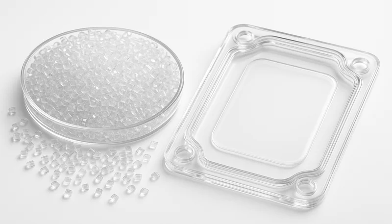
Wtrysk zbrojony włóknem węglowym to proces formowania wypełnionego włóknem termoplastu w lekkie, wysokosztywne części. Włókna, zwykle o długości 0.2–0.5 mm po komponowaniu, wzmacniają osnowę z PA6, PA66, PBT, PPS, PEEK lub PC. Podczas napełniania wnęki włókna orientują się wzdłuż kierunku przepływu stopu, tworząc właściwości mechaniczne zależne od kierunku. Ta anizotropia jest jednym z najważniejszych czynników, które inżynierowie muszą uwzględnić podczas projektowania części i formy. W przeciwieństwie do kompozytów z włóknem ciągłym, które wymagają autoklawów lub RTM, termoplasty zbrojone włóknem krótkim pracują na konwencjonalnych formowanie wtryskowe maszyn — skalowalne od 1000 do milionów części.
Włókna węglowe działają jako faza wzmacniająca w osnowie termoplastycznej — najczęściej PA6, PA66, PBT, PPS, PEEK lub PC. Podczas napełniania wnęki włókna orientują się wzdłuż kierunku przepływu stopu, tworząc części o właściwościach mechanicznych zależnych od kierunku. Ta anizotropia jest jednym z najważniejszych czynników, które inżynierowie muszą uwzględnić podczas projektowania części i formy.
W naszym doświadczeniu z tysiącami wtrysków kompozytów wzmacnianych włóknem węglowym zaobserwowaliśmy włókna krótkie nawet do 0,1 mm po przetworzeniu przez wąskie przewężenia. Kluczowa lekcja: projekt przewężenia i zachowanie długości włókien mają większe znaczenie niż surowy procent włókien podany w karcie materiałowej.
„Wtrysk zbrojony włóknem węglowym może wytwarzać części o stosunku wytrzymałości do masy przewyższającym aluminium odlewane ciśnieniowo.”Prawda
CF-PA6 przy 30% napełnienia osiąga ~200 MPa wytrzymałości na rozciąganie przy gęstości ~1.4 g/cm3, w porównaniu do ~180 MPa dla odlewanego ciśnieniowo aluminium A380 o gęstości 2.7 g/cm3 — co daje części polimerowej około 2× większą wytrzymałość właściwą.
„Wtrysk zbrojony włóknem węglowym wymaga specjalistycznego sprzętu, którego standardowe wtryskarki nie są w stanie obsłużyć.”Fałsz
Mieszanki CFRTP można przetwarzać na konwencjonalnych wtryskarkach. Główne modyfikacje to wyższe ciśnienie wtrysku (o 20–50% większe) oraz utwardzone zespoły ślimaka/cylindra odporne na ścieranie przez włókna — nie jest to zasadniczo odmienna konstrukcja maszyny.
Dlaczego warto wybrać wzmocnione włóknem węglowym tworzywa termoplastyczne?
Wzmocnione włóknem węglowym tworzywa termoplastyczne to kompozyty zapewniające wysoką sztywność, niski CTE i przewodność w jednym materiale. Inżynierowie wybierają je, gdy oszczędność masy, precyzja wymiarowa lub ekranowanie EMI uzasadniają 2–5-krotnie wyższą cenę materiału w porównaniu z gatunkami niezbrojonymi.
Wysoka sztywność właściwa: Moduł zginania CF-PA6 przy 30% napełnienia osiąga ~20 GPa — porównywalny z aluminium odlewanym ciśnieniowo przy jednej trzeciej gęstości. W zastosowaniach krytycznych wagowo, takich jak uchwyty akumulatorów EV czy ramy dronów, osiąga się cele konstrukcyjne przy znacznie mniejszej masie.
Stabilność wymiarowa: CTE spada z ~80 × 10⁻⁶/K (niewypełnione PA6) do ~20 × 10⁻⁶/K przy 30% CF. Ma to znaczenie dla precyzyjnych zespołów, gdzie cykle termiczne mogłyby wypchnąć części poza tolerancję.
Zmniejszona skurczliwość w formie: Całkowity skurcz spada z 1,0–1,5% (niewypełnione PA6) do 0,2–0,5% przy 30% CF, umożliwiając węższe tolerancje wymiarowe — choć anizotropowy skurcz wprowadza własne wyzwania.
Przewodność elektryczna: Włókno węglowe tworzy sieć przewodzącą przy zawartościach powyżej ~15%, umożliwiając ekranowanie EMI bez dodatkowych powłok lub metalowych wkładek.
Kompromisy: PA6-CF301 granulaty kosztują 8–15 zł/kg w porównaniu do 2–4 zł/kg dla niezbrojonego PA6. Włókna szybko tępią narzędzia skrawające podczas obróbki wtórnej, a recykling jest bardziej złożony, ponieważ wiązanie włókno-osnowa pogarsza się z każdym cyklem przetwarzania.
Jak zawartość włókien wpływa na przetwórstwo?
Wyższe napełnienie włóknem zwiększa sztywność, ale także podnosi lepkość, ciśnienie wtrysku, zużycie narzędzia i ryzyko ścinania w przewężeniu. Praktyczny optymalny zakres to 20-30% CF, gdzie osiąga się większość korzyści wytrzymałościowych bez nadmiernych trudności przetwórczych.
| Zawartość CF | Indeks lepkości stopu | Wytrzymałość na rozciąganie | Moduł sprężystości | Mold Shrinkage | Szybkość zużycia narzędzia |
|---|---|---|---|---|---|
| 0% (niezapełniony) | Baseline (1×) | ~80 MPa | ~2.8 GPa | 1.0–1.5% | Pomijalne |
| 10% | 1.3× | ~120 MPa | ~6 GPa | 0,5–0,8% | Niski |
| 20% | 1,8× | ~160 MPa | ~13 GPa | 0.3–0.5% | Umiarkowany |
| 30% | 2.5× | ~200 MPa | ~20 GPa | 0.2–0.4% | Wysoki |
| 40% | 3.5× | ~210 MPa | ~24 GPa | 0.1–0.3% | Bardzo wysoka |
Tensile strength plateaus around 30% loading — going from 30% to 40% gives only ~5% more strength but significantly more processing difficulty. In practice, 20–30% carbon fiber is the sweet spot for most structural applications. We have run thousands of shots of PA6-CF30 on our 90T–1850T machines and it consistently delivers the best balance.
“Increasing carbon fiber content from 30% to 40% yields diminishing returns in tensile strength while significantly increasing processing difficulty.”Prawda
Tensile strength goes from ~200 MPa at 30% CF to ~210 MPa at 40% CF — only a 5% gain — while melt viscosity jumps from 2.5× to 3.5× baseline, requiring much higher injection pressure and causing faster mold wear.
“Higher carbon fiber loading always produces stronger parts regardless of fiber orientation2.”Fałsz
Fiber orientation matters as much as loading. In the transverse direction, a 30% CF part may have only ~60–80 MPa tensile strength — less than the 80 MPa of isotropic unfilled PA6 in some cases. Design for the actual orientation in your part.
What Are the Key Processing Parameters?
Key parameters are melt temperature, injection speed, mold temperature, drying, and holding pressure. For PA6-CF30, target 260-285°C melt, 80-120 mm/s injection speed, 80-100°C mold temperature, and 40-60% holding pressure relative to injection pressure. Tighter control than unfilled resins is essential because fibers increase viscosity and accelerate heat transfer.
Temperatura topnienia
CF-filled resins need slightly higher barrel temperatures — typically 10–20°C above the unfilled grade — because fibers increase melt viscosity. For PA6-CF30, target 260–285°C. Do not exceed the upper limit; thermal degradation of the coupling agent between fiber and matrix weakens the part.
Prędkość i ciśnienie wtrysku
Expect 20–50% more injection pressure versus unfilled resin at the same mold temperature. A fast injection speed (80–120 mm/s) helps pack the mold before the high-viscosity melt freezes — but too fast, and fiber orientation concentrates at weld lines. Start at 100 mm/s and adjust.

Temperatura formy
Higher mold temperatures (80–100°C for PA6-CF) improve surface finish and reduce residual stress. Carbon fibers conduct heat away from the melt faster than the polymer matrix, so actual freeze time is shorter than expected — this can reduce cycle times by 10–15% compared to unfilled material.
Holding Pressure and Time
CF-filled parts shrink less, so holding pressure can be lower (40–60% of injection pressure versus 60–80% for unfilled). Holding time is shorter since the gate freezes faster. Test specimens per ASTM D36413 help dial in parameters objectively.
Jak projektować formy do materiałów wypełnionych włóknem węglowym?
Mold design for carbon fiber reinforced forma wtryskowa applications is where many projects go sideways. The fibers are abrasive, the viscosity is high, and fiber orientation creates directional property differences.
Steel Selection
Standard P20 tool steel will not survive long with carbon fiber compounds. After roughly 50,000 shots of 30% CF material, measurable wear appears on cavity surfaces and gate inserts. Use hardened tool steel (H13 at 48–52 HRC minimum, or S136 for corrosive materials) for production molds. For runs above 500,000 parts, TiN or DLC coatings on high-wear areas are worthwhile.
Konstrukcja bramy
This is the single most critical design decision. Small pin-point gates shred carbon fibers — you lose 30–50% of fiber length at the gate. Use edge gates, fan gates, or tab gates with minimum 1.5 mm thickness and short gate lands (0.5–1.0 mm) to minimize shear.
Runner System and Ejection
Full-round runners with 6–10 mm diameters reduce fiber breakage. Avoid sharp turns. Hot runners need hardened nozzles. For ejection, use 1.5–2° draft minimum (versus 0.5–1° for unfilled) and consider stripper plates for deep-core parts.
Jakie są typowe wady i jak je naprawić?
Common defects we encounter in carbon fiber reinforced molding are fiber exposure, weak weld lines, warpage, and short shots. After running CF-filled parts on our 90T–1850T machines for over two decades, fiber exposure and weld-line weakness are the two issues we debug most often on the production floor.
Fiber exposure: Visible fibers on the surface occur at loadings above 15–20% when the polymer matrix cannot fully encapsulate fibers. Increase mold temperature by 10–15°C and reduce injection speed slightly to let the polymer skin form first.
Weld line weakness: Fibers align parallel to weld lines — they cannot bridge the interface. The weld area can be 40–60% weaker. Position weld lines in non-critical areas using flow simulation, or add overflow wells to push weak zones outside the functional part.
Warpage from anisotropic shrinkage: Fiber-filled materials shrink more across the flow direction than along it. Thin-wall sections that cannot orient fibers freely shrink isotropically while adjacent thick sections do not. Counter this with uniform wall thickness and balanced gate placement.
Short shots in thin walls: CF-filled melts are 2–3× more viscous than unfilled resin, which causes short shots in walls thinner than 1.2 mm. Our engineers solve this by increasing injection speed to fill thin sections before the high-viscosity melt freezes, and by polishing cavity surfaces to reduce flow resistance.
“Weld lines in carbon fiber reinforced injection molded parts can be 40–60% weaker than the surrounding material.”Prawda
Fibers cannot bridge the weld line interface — they align parallel to it, leaving only the polymer matrix to carry load. This is why weld line placement must be addressed during mold design.
“Increasing injection pressure always eliminates short shots in thin-wall carbon fiber molding.”Fałsz
Excessive pressure without adequate venting causes flash and trapped-air burns. The right fix combines optimized melt temperature, proper vent depth, and minimum 1.0 mm wall thickness.
Które branże najwięcej zyskują na wtrysku CFRP?
When the performance-to-weight ratio matters, carbon fiber reinforced injection molding is hard to beat. These sectors see the most demand.
Automotive and Aerospace
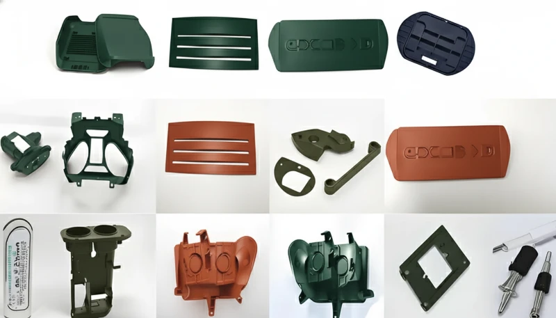
Lightweighting mandates in EVs drive demand for CF-PA6 and CF-PBT brackets, sensor housings, and battery module frames. A typical EV bracket in PA6-CF30 weighs 40% less than aluminum while meeting the same crash requirements. Aerospace uses CF-PEEK and CF-PPS for interior brackets and drone components where weight savings translate directly to fuel savings.
Electronics, Medical, and Consumer Products
Laptop hinges, smartphone mid-frames, and drone arms leverage CF-filled molding. The conductivity provides built-in EMI shielding. In medical devices, CFR-PEEK is radiolucent and biocompatible — ideal for surgical instruments and imaging-compatible housings.
Jak wybrać dostawcę wtrysku z włóknem węglowym?
A carbon fiber molding supplier is qualified by four factors: tooling steel, machine range, drying infrastructure, and ISO certification. Evaluate these criteria when selecting a sourcing partner for CFRP projects.
Equipment: The molder needs machines with sufficient injection pressure and precise temperature control. Machines from 90T to 1850T clamp force cover most CF molding applications.
Mold-making expertise: Your supplier needs in-house mold manufacturing with hardened steel capability. Ask if H13 or S136 is standard for fiber-filled production molds.
Obsługa materiałów: CF compounds — especially PA-based grades — are hygroscopic. The supplier must have dehumidifying dryers and keep material sealed until use.
Quality systems: ISO 9001 is the baseline. For medical, look for ISO 13485. For automotive, IATF 16949. A structured IQC → FQC → OQC gate system ensures consistency.
With 20+ years of injection molding experience, 45 machines from 90T to 1850T, in-house mold manufacturing delivering 100+ sets per month, and 400+ materials in our processing portfolio, we have encountered every challenge carbon fiber reinforced molding presents. Our 8 senior engineers (each with 10+ years of experience) design molds specifically for abrasive, fiber-filled compounds — using hardened steel, optimized gate geometry, and validated flow simulation before steel is cut.
Before tooling, run a short DFM checkpoint with the supplier: confirm fiber direction, gate wear risk, drying window, venting depth, and acceptance criteria. This prevents late surprises when stiffness targets, cosmetic expectations, and production yield compete during validation.
Jakie są najczęstsze pytania dotyczące wtrysku z włóknem węglowym?
Często zadawane pytania
What is the typical carbon fiber loading for injection molding?
Most commercial carbon fiber reinforced injection molding grades contain 10–30% carbon fiber by weight. Below 10%, the reinforcement effect is minimal and rarely worth the material cost premium. Above 30%, processing difficulty increases sharply — higher viscosity demands more injection pressure, mold wear accelerates, and fiber breakage at gates reduces the mechanical benefit. The sweet spot for most structural applications is 20–30% CF loading, where you capture the majority of strength and stiffness gains while keeping the process window manageable on conventional equipment.
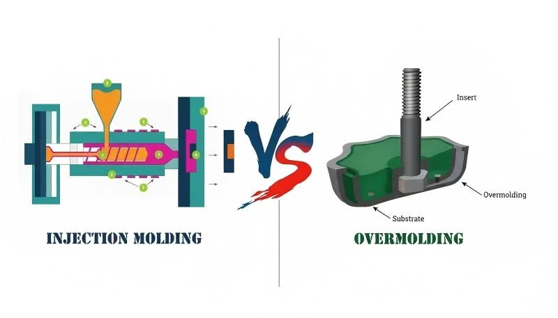
Can carbon fiber reinforced plastics be overmolded?
Yes, overmolding is a common approach for CFRP parts where surface aesthetics or tactile grip matter. The typical process molds a CF-reinforced structural substrate first, then overmolds with a soft TPE or TPU skin in a second shot. The key is ensuring the substrate surface is clean and warm enough for chemical bonding during the second shot — usually achieved by transferring the substrate directly from the first cavity to the overmold cavity while still hot. This two-shot approach lets you combine structural performance with a consumer-friendly surface finish.
Why do carbon fiber molded parts have visible fibers on the surface?
At fiber loadings above 15–20%, the polymer matrix cannot fully encapsulate all fibers at the part surface, especially when mold temperature is low or injection speed is too high. The fibers get pushed to the surface before a smooth polymer skin can form. Increasing mold temperature by 10–15°C and slightly reducing injection speed usually resolves this by giving the polymer more time to flow and create a uniform skin layer. For appearance-critical parts where surface quality is non-negotiable, painting or overmolding with an unfilled skin layer is the standard industry practice.
Is carbon fiber reinforced injection molding expensive?
Material cost is 2–5× higher than unfilled grades — PA6-CF30 pellets run $8–15/kg versus $2–4/kg for unfilled PA6. Mold costs are also higher because hardened tool steel (H13 or S136) replaces standard P20, adding 15–25% to the tooling investment. However, for applications where weight savings translate to system-level cost reductions (fewer fasteners, simplified assembly, reduced shipping weight), the total cost of ownership is often lower. An EV bracket that costs $0.50 more in material but eliminates two metal fasteners and reduces assembly time by 30 seconds can be net-positive on cost.
What shrinkage should I design for with carbon fiber filled nylon?
PA6 with 30% carbon fiber has mold shrinkage of approximately 0.2–0.4% in the flow direction and 0.4–0.7% in the transverse direction. This is significantly less than unfilled PA6 (1.0–1.5%), which is good for dimensional tolerance. However, the anisotropy — different shrinkage in different directions — requires careful mold design, especially for flat or thin-wall parts prone to warpage. Always run mold flow simulation to predict fiber orientation before finalizing cavity dimensions, and use the simulation results to apply directional shrinkage compensation rather than a single uniform value.
Can recycled carbon fiber be used in injection molding?
Yes, reclaimed carbon fiber from aerospace manufacturing scrap or pyrolysis recycling can be compounded into injection molding pellets. The recycled fiber length is typically shorter (0.1–0.3 mm versus 0.2–0.5 mm for virgin CF compounds), resulting in approximately 15–25% lower tensile strength and modulus. The cost reduction is significant — often 40–60% cheaper than virgin CF compounds — making recycled CF grades attractive for non-critical structural applications, interior automotive components, and consumer products where the performance premium of virgin fiber is not justified.
How do I prevent mold wear when molding carbon fiber parts?
Use hardened tool steel (H13 at 48–52 HRC minimum, or S136 stainless for corrosive resin grades) for all cavity and core surfaces that contact the melt. Apply TiN or DLC coatings to high-wear areas like gate inserts, sliding lifter faces, and thin-wall sections. Design generous gate dimensions to reduce shear velocity and fiber impact force on the gate land. Schedule regular cavity measurements every 20,000–50,000 shots to catch dimensional drift before it affects part quality. For very high-volume production, consider insert-based mold construction so worn gate areas can be replaced without re-cutting the entire cavity [4].
What is the difference between glass fiber and carbon fiber reinforced injection molding?
Both fibers improve stiffness and strength, but carbon fiber delivers approximately 30–40% higher stiffness at equal loading, lower density (1.8 g/cm versus 2.5 g/cm for glass fiber), electrical conductivity at loadings above 15%, and a lower coefficient of thermal expansion. Glass fiber is significantly cheaper — $3–6/kg for GF-compounded pellets versus $8–15/kg for CF grades. Glass fiber also has higher elongation at break, making GF parts more impact-resistant. Choose glass fiber when cost is the primary driver and impact toughness matters; choose carbon fiber when weight savings, stiffness-to-weight ratio, or EMI conductivity justify the material premium.
Ready to bring your carbon fiber reinforced injection molding project to production? With 45 machines (90T–1850T), in-house mold manufacturing, 400+ materials processed, and ISO 9001/13485/14001/45001 certifications, our engineering team can take your design from prototype to volume production. Get a free quote and DFM review from our senior engineers — typically within 24 hours.
-
PA6-CF30: PA6-CF30 (Nylon 6 with 30% short carbon fiber by weight) is a widely used injection molding compound offering approximately 200 MPa tensile strength and 20 GPa flexural modulus, per manufacturer datasheets. ↩
-
fiber orientation: Fiber orientation refers to the directional alignment of short fibers along the melt flow path during cavity filling, causing tensile strength in the flow direction to be 2–3 times higher than in the transverse direction. ↩
-
ASTM D3641: ASTM D3641 is a standard practice for injection molding test specimens of thermoplastic molding and extrusion materials, providing a repeatable baseline for comparing mechanical properties across resin grades. ↩


