Karbon elyaf takviyeli enjeksiyon kalıplama, alüminyumdan daha hafif ancak takviyesiz plastiklerden daha güçlü parçalar üretir. Ağırlık cezası olmadan rijitlik gerektiren braketler, muhafazalar veya yapısal bileşenler tasarlıyorsanız bu proses dikkatinizi hak eder. Bu kılavuz; atölyede edinilmiş yirmi yıllık uygulamalı deneyime dayanarak malzeme seçimini, işleme parametrelerini, kalıp tasarımını ve kusur giderme yöntemlerini ele alır.
- Karbon fiber içeriği tipik olarak enjeksiyon kalıplama bileşiklerinde ağırlıkça –40% aralığındadır.
- Lif dolgulu eriyikler, doldurulmamış reçinelere göre –50% daha yüksek enjeksiyon basıncına ihtiyaç duyar.
- Karbon fiberler son derece aşındırıcı olduğu için sertleştirilmiş kalıp çeliği (H13, S136) şarttır.
- Büyük, yuvarlatılmış geçitler, fiber kırılmasını azaltır ve geçit bölgesindeki mekanik mukavemeti korur.
- Akış yönündeki çekme dayanımı, enine yöndekinden 2–3 kat daha yüksek olabilir.
Karbon Fiber Takviyeli Enjeksiyon Kalıplama Nedir?
Karbon fiber takviyeli enjeksiyon kalıplama, fiber dolgulu termoplastiğin hafif ve yüksek rijitlikte parçalara kalıplanması prosesidir. Birleştirme sonrasında genellikle 0,2-0,5 mm uzunluğunda olan fiberler PA6, PA66, PBT, PPS, PEEK veya PC matrisini takviye eder. Kalıp gözü dolarken fiberler eriyik akış yönünde hizalanarak yöne bağlı mekanik özellikler oluşturur. Bu anizotropi, mühendislerin parça ve kalıp tasarımında hesaba katması gereken en önemli etkenlerden biridir. Otoklav veya RTM gerektiren sürekli fiber kompozitlerin aksine kısa fiber takviyeli termoplastikler geleneksel enjeksiyon kalıplama makinelerinde çalışır ve 1.000 parçadan milyonlarca parçaya ölçeklenebilir.
Karbon fiberler, genellikle PA6, PA66, PBT, PPS, PEEK veya PC olan bir termoplastik matris içinde takviye fazı görevi görür. Boşluk dolumu sırasında fiberler eriyik akış yönünde yönlenerek, yöne bağlı mekanik özelliklere sahip parçalar oluşturur. Bu anizotropi, mühendislerin parça ve kalıp tasarımında dikkate alması gereken en önemli faktörlerden biridir.
Binlerce karbon fiber takviyeli bileşik enjeksiyon deneyimimizde, dar geçitlerden bileşikleme sonrasında 0.1 mm kadar kısa fiberler gördük. Anahtar ders: geçit tasarımı ve fiber uzunluğunun korunması, veri sayfasındaki ham fiber yüzdesinden daha önemlidir.
"Karbon elyaf takviyeli enjeksiyon kalıplama, basınçlı döküm alüminyumdan daha yüksek dayanım-ağırlık oranına sahip parçalar üretebilir."True
CF-PA6 yüklemesi, yaklaşık 1,4 g/cm³ yoğunlukta ~200 MPa çekme dayanımına ulaşırken, 2,7 g/cm³ yoğunluğa sahip döküm A380 alüminyum için bu değer ~180 MPa'dır — bu da polimer parçaya yaklaşık 2 kat spesifik dayanım sağlar.
"Karbon fiber takviyeli enjeksiyon kalıplama, standart enjeksiyon makinelerinin karşılayamayacağı özel ekipman gerektirir."False
CFRTP bileşikleri geleneksel enjeksiyon kalıplama makinelerinde çalıştırılır. Ana ayarlamalar, daha yüksek enjeksiyon basıncı (–50 daha fazla) ve fiber aşınmasına dayanıklı sertleştirilmiş vida/namlu gruplarıdır — temelde farklı bir makine mimarisi değildir.
Neden Karbon Fiber Takviyeli Termoplastikler Seçilmeli?
Karbon fiber takviyeli termoplastikler, tek bir malzemede yüksek rijitlik, düşük CTE ve iletkenlik sunan kompozitlerdir. Mühendisler, ağırlık tasarrufu, boyutsal hassasiyet veya EMI kalkanlaması, dolgusuz sınıflara göre 2–5 kat malzeme maliyeti farkını haklı çıkardığında bunları seçer.
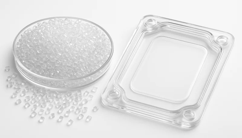
Yüksek özgül rijitlik: %30 dolgu oranındaki CF-PA6’nın eğilme modülü yaklaşık 20 GPa’ya ulaşır; bu, üçte bir yoğunlukta basınçlı döküm alüminyumla karşılaştırılabilir. EV batarya braketleri veya drone çerçeveleri gibi ağırlığın kritik olduğu uygulamalarda çok daha az kütleyle yapısal hedefleri karşılarsınız.
Boyutsal kararlılık: CTE, dolgusuz PA6’da yaklaşık 80 × 10⁻/K iken %30 CF oranında yaklaşık 20 × 10⁻/K’ye düşer. Bu, termal çevrimlerin parçaları tolerans dışına çıkarabileceği hassas montajlar için önemlidir.
Azalan kalıp çekmesi: Toplam çekme, dolgusuz PA6’daki %1,0-1,5 düzeyinden %30 CF’de %0,2-0,5’e düşerek daha dar boyutsal toleranslara imkân verir; ancak anizotropik çekme kendi zorluklarını doğurur.
Elektrik iletkenliği: Karbon fiber, yaklaşık %15 üzerindeki dolgu oranlarında iletken bir ağ oluşturarak ikincil kaplamalar veya metal insertler olmadan EMI koruması sağlar.
Ödünleşimler: PA6-CF301 granüllerinin fiyatı 8-15 $/kg iken dolgusuz PA6’nın fiyatı 2-4 $/kg’dır. Fiberler ikincil talaşlı işlemlerde kesici takımları hızla köreltir ve fiber-matris bağı her yeniden işleme çevriminde bozulduğundan geri dönüşüm daha karmaşıktır.
Fiber İçeriği İşlemeyi Nasıl Etkiler?
Daha yüksek fiber yüklemesi bir sertlik kazancıdır, ancak aynı zamanda viskoziteyi, enjeksiyon basıncını, takım aşınmasını ve geçit-kayma riskini artırır. Pratik optimum nokta, aşırı işleme zorluğu olmadan çoğu mukavemet kazancının elde edildiği -30 CF yüklemesidir.
| CF Yükleme | Ergimiş Viskozite İndeksi | Çekme Dayanımı | Eğilme Modülü | Kalıp Çekmesi | Takım Aşınma Oranı |
|---|---|---|---|---|---|
| 0% (dolgusuz) | Temel (1×) | yaklaşık 80 MPa | Yaklaşık 2,8 GPa | 1.0–1.5% | Önemsiz |
| 10% | 1.3× | Yaklaşık 120 MPa | ~6 GPa | 0.5–0.8% | Düşük |
| 20% | 1.8× | Yaklaşık 160 MPa | Yaklaşık ~13 GPa | 0.3–0.5% | Orta düzeyde |
| 30% | 2.5× | Değer: ~200 MPa | ~20 GPa düzeyinde | 0.2–0.4% | Yüksek |
| 40% | 3.5× | Yaklaşık ~210 MPa | yaklaşık ~24 GPa | 0.1–0.3% | Çok Yüksek |
Çekme dayanımı yaklaşık 30% yükleme düzeyinde plato yapar; 30% değerinden 40% değerine çıkmak yalnızca ~5% daha fazla dayanım sağlarken işleme güçlüğünü önemli ölçüde artırır. Uygulamada 20–30% karbon elyaf, yapısal uygulamaların çoğu için en uygun aralıktır. PA6-CF30 ile 90T–1850T makinelerimizde binlerce baskı yaptık ve bu malzeme sürekli olarak en iyi dengeyi sağladı.
"Karbon elyaf içeriğini 30%'dan 40%'a çıkarmak çekme dayanımında azalan getiri sağlarken işleme güçlüğünü önemli ölçüde artırır."True
Çekme dayanımı 30% CF'de ~200 MPa'dan 40% CF'de ~210 MPa'ya çıkar — yalnızca 5% artış — buna karşılık eriyik viskozitesi temel değerin 2.5× katından 3.5× katına sıçrar; bu da çok daha yüksek enjeksiyon basıncı gerektirir ve kalıbın daha hızlı aşınmasına neden olur.
"Daha yüksek karbon fiber oranı, fiber yönlenmesinden bağımsız olarak her zaman daha güçlü parçalar üretir2."False
Elyaf yönlenmesi, yükleme oranı kadar önemlidir. Enine yönde 30% CF içeren bir parça yalnızca ~60–80 MPa çekme dayanımına sahip olabilir — bazı durumlarda izotropik, dolgusuz PA6'nın 80 MPa değerinden daha düşüktür. Tasarımı parçanızdaki gerçek yönlenmeye göre yapın.
Temel İşleme Parametreleri Nelerdir?
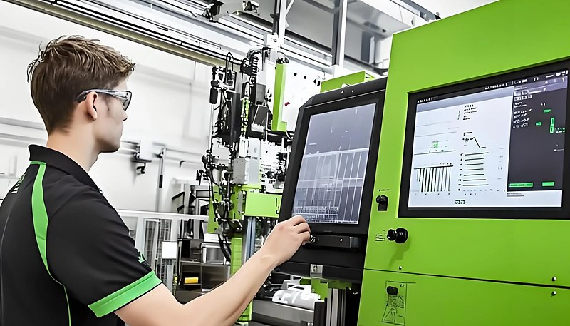
Temel parametreler eriyik sıcaklığı, enjeksiyon hızı, kalıp sıcaklığı, kurutma ve tutma basıncıdır. PA6-CF30 için hedefler: 260-285°C eriyik, 80-120 mm/s enjeksiyon hızı, 80-100°C kalıp sıcaklığı ve enjeksiyon basıncına göre 40-60% tutma basıncı. Lifler viskoziteyi artırıp ısı transferini hızlandırdığı için dolgusuz reçinelere kıyasla daha sıkı kontrol şarttır.
Erime Sıcaklığı
CF dolgulu reçineler biraz daha yüksek silindir sıcaklıklarına — elyaflar eriyik viskozitesini artırdığı için tipik olarak dolgusuz kaliteden 10–20°C daha yüksek — ihtiyaç duyar. PA6-CF30 için 260–285°C hedefleyin. Üst sınırı aşmayın; elyaf ile matris arasındaki bağlayıcı ajanın ısıl bozunması parçayı zayıflatır.
Enjeksiyon Hızı ve Basıncı
Aynı kalıp sıcaklığında dolgusuz reçineye göre 20–50% daha fazla enjeksiyon basıncı bekleyin. Yüksek enjeksiyon hızı (80–120 mm/s), yüksek viskoziteli eriyik donmadan önce kalıbın doldurulmasına yardımcı olur; ancak hız aşırı olursa elyaf yönlenmesi birleşme çizgilerinde yoğunlaşır. 100 mm/s ile başlayıp ayarlayın.
Kalıp Sıcaklığı
Daha yüksek kalıp sıcaklıkları (PA6-CF için 80–100°C) yüzey kalitesini iyileştirir ve artık gerilimi azaltır. Karbon elyafları ısıyı eriyikten polimer matristen daha hızlı uzaklaştırır; bu nedenle gerçek donma süresi beklenenden kısadır. Bu, dolgusuz malzemeye kıyasla çevrim sürelerini 10–15% azaltabilir.
Tutma Basıncı ve Süresi
CF dolgulu parçalar daha az çektiğinden tutma basıncı daha düşük olabilir (dolgusuz malzemelerde enjeksiyon basıncının %60-80’i yerine %40-60’ı). Giriş daha hızlı donduğu için tutma süresi daha kısadır. ASTM D36413 standardına uygun test numuneleri, parametrelerin nesnel biçimde ayarlanmasına yardımcı olur.
Karbon Fiber Dolgulu Malzemeler için Kalıplar Nasıl Tasarlanır?
Karbon fiber takviyeli enjeksiyon kalıbı uygulamalarında kalıp tasarımı, birçok projenin raydan çıktığı noktadır. Fiberler aşındırıcıdır, viskozite yüksektir ve fiber yönelimi yöne bağlı özellik farklılıkları oluşturur.
Çelik Seçimi
Standart P20 takım çeliği, karbon fiber bileşiklerle uzun süre dayanmaz. 30% CF malzemeyle yaklaşık 50,000 baskıdan sonra kalıp gözü yüzeylerinde ve yolluk giriş ek parçalarında ölçülebilir aşınma görülür. Üretim kalıplarında sertleştirilmiş takım çeliği kullanın: en az 48–52 HRC sertlikte H13 veya korozif malzemeler için S136. 500,000 parçanın üzerindeki serilerde yüksek aşınmalı alanlara TiN ya da DLC kaplama uygulamak avantajlıdır.
Kapı Tasarımı
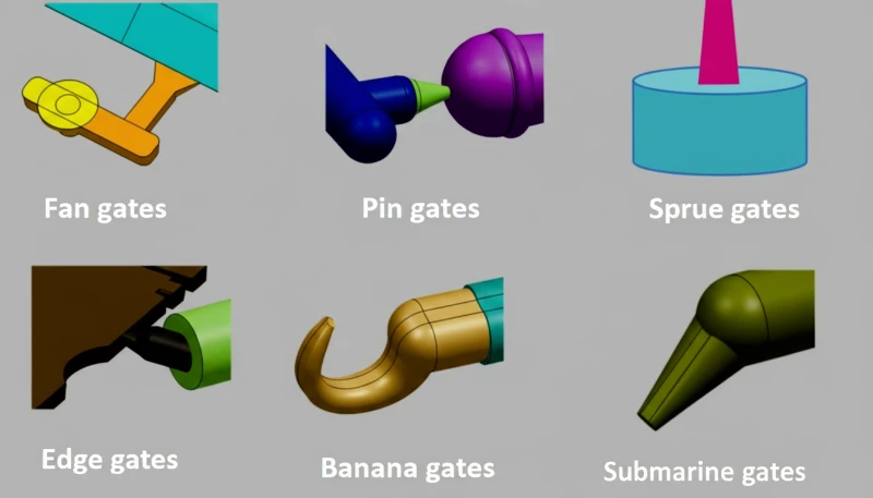
Bu, en kritik tasarım kararıdır. Küçük iğne uçlu kapılar karbon fiberleri parçalar; kapıda fiber uzunluğunun 30–50%‘sini kaybedersiniz. Kaymayı en aza indirmek için en az 1.5 mm kalınlığa ve kısa kapı geçişlerine (0.5–1.0 mm) sahip kenar kapıları, yelpaze kapıları veya kulaklı kapılar kullanın.
Yolluk Sistemi ve Çıkarma
6–10 mm çaplı tam yuvarlak yolluklar fiber kırılmasını azaltır. Keskin dönüşlerden kaçının. Sıcak yolluklarda sertleştirilmiş memeler gerekir. İtme için en az 1.5–2° kalıp açısı kullanın (dolgusuz malzemelerde 0.5–1°) ve derin maçalı parçalar için sıyırıcı plakaları değerlendirin.
Yaygın Kusurlar Nelerdir ve Nasıl Düzeltilir?
Karbon fiber takviyeli kalıplamada karşılaştığımız yaygın kusurlar; fiber açığa çıkması, zayıf birleşme çizgileri, çarpılma ve eksik dolumdur. CF dolgulu parçaları 90T–1850T makinelerimizde yirmi yılı aşkın süredir üretirken, üretim sahasında en sık fiber açığa çıkması ve birleşme çizgisi zayıflığını giderdik.
Fiber açığa çıkması: Polimer matrisinin fiberleri tamamen kapsayamadığı %15-20 üzerindeki dolgu oranlarında yüzeyde görünür fiberler oluşur. Önce polimer kabuğunun oluşmasını sağlamak için kalıp sıcaklığını 10-15°C artırın ve enjeksiyon hızını biraz düşürün.
Birleşme çizgisi zayıflığı: Fiberler birleşme çizgilerine paralel hizalanır ve arayüzü köprüleyemez. Birleşme bölgesi %40-60 daha zayıf olabilir. Akış simülasyonuyla birleşme çizgilerini kritik olmayan bölgelere konumlandırın veya zayıf bölgeleri işlevsel parçanın dışına taşımak için taşma cepleri ekleyin.

Anizotropik çekmeden kaynaklanan çarpılma: Fiber dolgulu malzemeler akış yönüne kıyasla enine yönde daha fazla çeker. Fiberlerin serbestçe yönlenemediği ince duvarlı kesitler izotropik çekerken bitişikteki kalın kesitler böyle davranmaz. Bunu eşit duvar kalınlığı ve dengeli giriş yerleşimiyle önleyin.
İnce duvarlarda eksik dolum: CF dolgulu eriyiklerin viskozitesi dolgusuz reçinenin 2-3 katıdır; bu da 1,2 mm’den ince duvarlarda eksik doluma yol açar. Mühendislerimiz, yüksek viskoziteli eriyik donmadan ince kesitleri doldurmak için enjeksiyon hızını artırarak ve akış direncini azaltmak için kalıp gözü yüzeylerini parlatarak bu sorunu çözer.
"Karbon elyaf takviyeli enjeksiyon kalıplı parçalardaki birleşme çizgileri, çevresindeki malzemeden 40–60% daha zayıf olabilir."True
Elyaflar kaynak çizgisi arayüzünü köprüleyemez — çizgiye paralel hizalandıkları için yükü yalnızca polimer matrisi taşır. Bu nedenle kaynak çizgisinin konumu kalıp tasarımı sırasında ele alınmalıdır.
"Enjeksiyon basıncını artırmak, ince cidarlı karbon fiber kalıplamada eksik dolumu her zaman ortadan kaldırır."False
Yeterli havalandırma olmadan aşırı basınç, çapak ve sıkışmış hava yanıklarına neden olur. Doğru çözüm; optimize edilmiş eriyik sıcaklığını, uygun havalandırma derinliğini ve minimum 1.0 mm et kalınlığını birlikte uygular.
Hangi Sektörler CFRP Enjeksiyon Kalıplamadan En Çok Faydalanır?
Performans-ağırlık oranı önemli olduğunda karbon elyaf takviyeli enjeksiyon kalıplamanın üstünlüğü zordur. En fazla talep bu sektörlerde görülür.
Otomotiv ve Havacılık
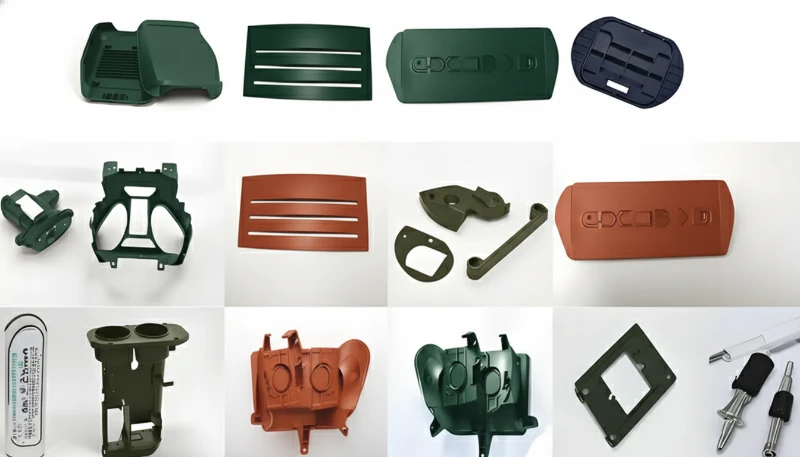
EV’lerde hafifletme zorunlulukları CF-PA6 ve CF-PBT braketlere, sensör muhafazalarına ve batarya modülü çerçevelerine talebi artırır. PA6-CF30’dan tipik bir EV braketi, aynı çarpışma gereksinimlerini karşılarken alüminyumdan 40% daha hafiftir. Havacılıkta, ağırlık tasarrufunun doğrudan yakıt tasarrufuna dönüştüğü iç braketler ve drone bileşenlerinde CF-PEEK ve CF-PPS kullanılır.
Elektronik, Tıbbi ve Tüketici Ürünleri
Dizüstü bilgisayar menteşelerinde, akıllı telefon orta kasalarında ve drone kollarında CF dolgulu kalıplamadan yararlanılır. İletkenlik, yerleşik EMI koruması sağlar. Tıbbi cihazlarda CFR-PEEK radyolüsent ve biyouyumludur — cerrahi aletler ve görüntülemeyle uyumlu muhafazalar için idealdir.
Karbon Fiber Enjeksiyon Kalıplama Tedarikçisi Nasıl Seçilir?
Bir karbon fiber kalıplama tedarikçisinin yeterliliği dört etkenle belirlenir: takım çeliği, makine aralığı, kurutma altyapısı ve ISO sertifikası. CFRP projeleri için tedarik ortağı seçerken bu ölçütleri değerlendirin.
Ekipman: Kalıpçının yeterli enjeksiyon basıncına ve hassas sıcaklık kontrolüne sahip makinelere ihtiyacı vardır. 90T ile 1850T arasındaki kapama kuvvetine sahip makineler çoğu CF kalıplama uygulamasını kapsar.
Kalıp yapım uzmanlığı: Tedarikçiniz sertleştirilmiş çelik işleyebilen şirket içi kalıp üretimine sahip olmalıdır. Fiber dolgulu üretim kalıplarında H13 veya S136’nın standart olup olmadığını sorun.
Malzeme elleçleme: CF bileşikleri, özellikle PA bazlı sınıflar, higroskopiktir. Tedarikçinin nem alıcılı kurutuculara sahip olması ve malzemeyi kullanıma kadar kapalı tutması gerekir.
Kalite sistemleri: ISO 9001 temel gerekliliktir. Tıbbi uygulamalar için ISO 13485, otomotiv için IATF 16949 arayın. Yapılandırılmış bir IQC → FQC → OQC kontrol sistemi tutarlılığı güvence altına alır.
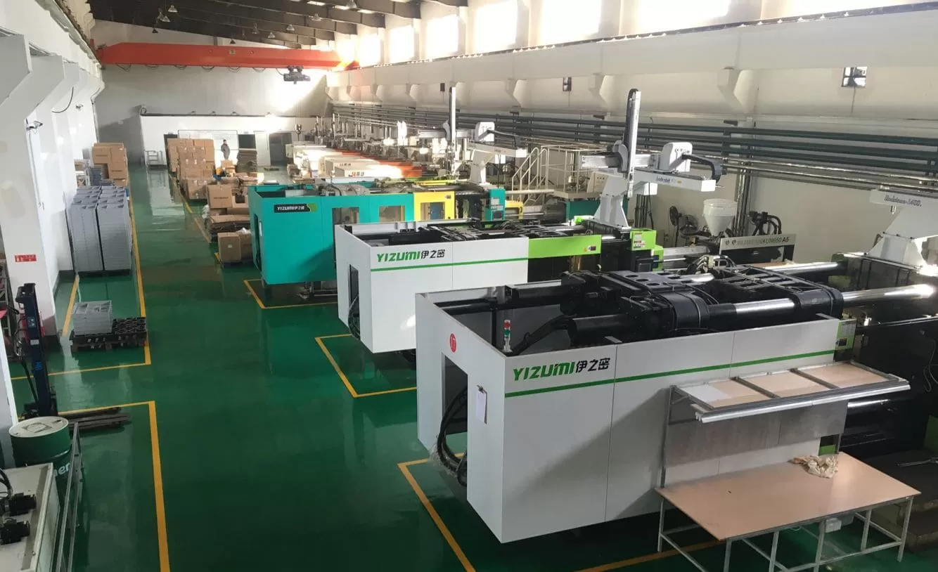
20+ yıllık enjeksiyon kalıplama deneyimimiz, 90T ile 1850T arasında 45 makinemiz, ayda 100+ set teslim eden şirket içi kalıp üretimimiz ve işleme portföyümüzdeki 400+ malzemeyle karbon fiber takviyeli kalıplamanın tüm zorluklarıyla karşılaştık. 8 kıdemli mühendisimiz, her biri 10+ yıllık deneyime sahip, aşındırıcı ve fiber dolgulu bileşikler için özel kalıplar tasarlar; çelik kesilmeden önce sertleştirilmiş çelik, optimize edilmiş giriş geometrisi ve doğrulanmış akış simülasyonu kullanır.
Kalıp üretiminden önce tedarikçiyle kısa bir DFM kontrolü yapın: elyaf yönünü, yolluk girişi aşınma riskini, kurutma penceresini, gaz tahliye derinliğini ve kabul kriterlerini doğrulayın. Bu, doğrulama sırasında rijitlik hedefleri, kozmetik beklentiler ve üretim verimi birbiriyle yarıştığında ortaya çıkabilecek geç sürprizleri önler.
Karbon Fiber Enjeksiyon Kalıplama Hakkında En Yaygın Sorular Nelerdir?
Sıkça Sorulan Sorular
Enjeksiyon kalıplamada tipik karbon fiber oranı nedir?
Ticari karbon elyaf takviyeli enjeksiyon kalıplama kalitelerinin çoğu ağırlıkça %10–30 karbon elyaf içerir. %10’un altında takviye etkisi sınırlıdır ve malzemenin ek maliyetine nadiren değer. %30’un üzerinde işleme güçlüğü hızla artar; daha yüksek viskozite daha fazla enjeksiyon basıncı gerektirir, kalıp aşınması hızlanır ve girişlerdeki elyaf kırılması mekanik faydayı azaltır. Çoğu yapısal uygulamada ideal aralık %20–30 CF yüklemesidir; bu aralık, geleneksel ekipmanda yönetilebilir bir süreç penceresini korurken mukavemet ve rijitlik kazanımlarının büyük bölümünü sağlar.
Karbon fiber takviyeli plastiklere üzerine kalıplama uygulanabilir mi?
Evet, yüzey estetiğinin veya dokunsal tutuşun önemli olduğu CFRP parçalarında üzeri kalıplama yaygın bir yaklaşımdır. Tipik süreçte önce CF takviyeli yapısal altlık kalıplanır, ardından ikinci baskıda yumuşak bir TPE veya TPU kaplama uygulanır. Kritik nokta, ikinci baskı sırasında kimyasal bağlanma için altlık yüzeyinin temiz ve yeterince sıcak olmasını sağlamaktır — bu genellikle altlık hâlâ sıcakken ilk boşluktan doğrudan üzeri kalıplama boşluğuna aktarılarak elde edilir. Bu iki baskılı yaklaşım, yapısal performansı tüketici dostu bir yüzey kalitesiyle birleştirmenizi sağlar.
Karbon Fiber Kalıplı Parçaların Yüzeyinde Neden Görünür Elyaflar Bulunur?
Fiber oranı 15–20% üzerine çıktığında, özellikle kalıp sıcaklığı düşük veya enjeksiyon hızı fazla yüksekse polimer matris parça yüzeyindeki tüm fiberleri tamamen kaplayamaz. Pürüzsüz bir polimer kabuk oluşmadan önce fiberler yüzeye itilir. Kalıp sıcaklığını 10–15°C artırmak ve enjeksiyon hızını biraz düşürmek, polimere akıp homojen bir kabuk tabakası oluşturması için daha fazla süre tanıyarak genellikle sorunu giderir. Yüzey kalitesinden ödün verilemeyen görünüm odaklı parçalarda boyama veya dolgusuz bir kabuk tabakasıyla üzeri kalıplama, standart sektör uygulamasıdır.
Karbon fiber takviyeli enjeksiyon kalıplama pahalı mıdır?
Malzeme maliyeti dolgusuz sınıflara göre 2–5× daha yüksektir; PA6-CF30 granülleri $8–15/kg iken dolgusuz PA6 $2–4/kg düzeyindedir. Standart P20 yerine sertleştirilmiş takım çeliği (H13 veya S136) kullanıldığı için kalıp maliyetleri de daha yüksektir ve kalıp yatırımına %15–25 ekler. Ancak ağırlık tasarrufunun sistem düzeyinde maliyet düşüşü sağladığı uygulamalarda (daha az bağlantı elemanı, basitleştirilmiş montaj, daha düşük sevkiyat ağırlığı) toplam sahip olma maliyeti çoğu zaman daha düşüktür. Malzemesi $0.50 daha pahalı olan ancak iki metal bağlantı elemanını ortadan kaldırıp montaj süresini 30 saniye azaltan bir EV braketi, net maliyet avantajı sağlayabilir.
Karbon elyaf dolgulu naylon için tasarımda hangi çekme oranını kullanmalıyım?
%30 karbon fiberli PA6’nın kalıp çekmesi akış yönünde yaklaşık %0.2–0.4, enine yönde ise %0.4–0.7’dir. Bu değer, dolgusuz PA6’ya (%1.0–1.5) göre belirgin biçimde daha düşüktür ve boyutsal tolerans açısından avantajlıdır. Ancak anizotropi, yani farklı yönlerde farklı çekme, özellikle çarpılmaya yatkın düz veya ince cidarlı parçalar için dikkatli kalıp tasarımı gerektirir. Kalıp gözü ölçülerini kesinleştirmeden önce lif yönlenmesini öngörmek için mutlaka kalıp akış simülasyonu yapın ve tek bir homojen değer yerine simülasyon sonuçlarına göre yönsel çekme telafisi uygulayın.
Geri dönüştürülmüş karbon elyaf enjeksiyon kalıplamada kullanılabilir mi?
Evet, havacılık imalatı hurdalarından veya piroliz geri dönüşümünden elde edilen geri kazanılmış karbon elyaf, enjeksiyon kalıplama granüllerine kompaund edilebilir. Geri dönüştürülmüş elyaf uzunluğu genellikle daha kısadır (işlenmemiş CF bileşiklerinde 0.2–0.5 mm iken 0.1–0.3 mm); bu da çekme dayanımı ve modülde yaklaşık %15–25 düşüşe yol açar. Maliyet avantajı büyüktür — çoğu zaman işlenmemiş CF bileşiklerinden %40–60 daha ucuzdur. Bu nedenle geri dönüştürülmüş CF sınıfları, işlenmemiş elyafın performans farkının gerekli olmadığı kritik olmayan yapısal uygulamalar, otomotiv iç parçaları ve tüketici ürünleri için caziptir.
Karbon fiber parçaları kalıplarken kalıp aşınmasını nasıl önlerim?
Eriyikle temas eden tüm boşluk ve maça yüzeylerinde sertleştirilmiş takım çeliği (minimum 48–52 HRC değerinde H13 veya aşındırıcı reçine sınıfları için S136 paslanmaz çelik) kullanın. Giriş insertleri, kayan kaldırıcı yüzeyleri ve ince cidarlı kesitler gibi yüksek aşınmalı bölgelere TiN veya DLC kaplama uygulayın. Giriş yüzeyindeki kesme hızını ve elyaf darbe kuvvetini azaltmak için geniş giriş ölçüleri tasarlayın. Boyutsal sapmayı parça kalitesini etkilemeden yakalamak için her 20,000–50,000 atışta düzenli boşluk ölçümleri planlayın. Çok yüksek hacimli üretimde, aşınmış giriş bölgelerinin tüm boşluk yeniden işlenmeden değiştirilebilmesi için insert tabanlı kalıp yapısını değerlendirin [4].
Cam elyaf ve karbon elyaf takviyeli enjeksiyon kalıplama arasındaki fark nedir?
Her iki elyaf da rijitliği ve mukavemeti artırır; ancak karbon elyaf eşit yükleme oranında yaklaşık %30–40 daha yüksek rijitlik, daha düşük yoğunluk (cam elyaf için 2.5 g/cm’ye karşı 1.8 g/cm), %15’in üzerindeki yükleme oranlarında elektrik iletkenliği ve daha düşük ısıl genleşme katsayısı sağlar. Cam elyaf önemli ölçüde daha ucuzdur — GF bileşik granüllerde $3–6/kg, CF sınıflarında ise $8–15/kg. Cam elyafın kopma uzaması da daha yüksektir ve bu, GF parçaları darbeye daha dayanıklı kılar. Öncelikli etken maliyetse ve darbe dayanımı önemliyse cam elyafı; ağırlık tasarrufu, rijitlik/ağırlık oranı veya EMI iletkenliği yüksek malzeme bedelini haklı çıkarıyorsa karbon elyafı seçin.
Karbon fiber takviyeli enjeksiyon kalıplama projenizi üretime taşımaya hazır mısınız? 45 makine (90T-1850T), şirket içi kalıp üretimi, işlenmiş 400’den fazla malzeme ve ISO 9001/13485/14001/45001 sertifikalarıyla mühendislik ekibimiz tasarımınızı prototipten seri üretime taşıyabilir. Kıdemli mühendislerimizden genellikle 24 saat içinde ücretsiz fiyat teklifi ve DFM incelemesi alın.
PA6-CF30: PA6-CF30 (ağırlıkça %30 kısa karbon fiber içeren Naylon 6), üretici veri sayfalarına göre yaklaşık 200 MPa çekme mukavemeti ve 20 GPa eğilme modülü sunan, yaygın kullanılan bir enjeksiyon kalıplama bileşiğidir. ↩
fiber yönelimi: Fiber yönelimi, kalıp gözü dolumu sırasında kısa fiberlerin eriyik akış yolu boyunca yönlü biçimde hizalanmasıdır; bunun sonucunda akış yönündeki çekme mukavemeti enine yöndekinden 2-3 kat yüksek olur. ↩
ASTM D3641: ASTM D3641, termoplastik kalıplama ve ekstrüzyon malzemelerinin enjeksiyonla kalıplanmış test numunelerine yönelik standart bir uygulamadır ve reçine sınıflarının mekanik özelliklerini karşılaştırmak için tekrarlanabilir bir temel sağlar. ↩