 Skip to content

Le moulage par injection renforcé de fibres de carbone produit des pièces plus légères que l'aluminium et plus résistantes que les plastiques non renforcés. Si vous concevez des supports, des boîtiers ou des composants structurels nécessitant de la rigidité sans pénalité de poids, ce processus mérite votre attention. Ce guide couvre la sélection des matériaux, les paramètres de traitement, la conception des moules et le dépannage des défauts – tirés de deux décennies d'expérience pratique sur le terrain.
- La teneur en fibres de carbone varie généralement de 10 à 40% en poids dans les composés pour moulage par injection.
- Les matériaux chargés en fibres nécessitent une pression d'injection de 20 à 50% supérieure à celle des résines non chargées.
- L'acier à moule durci (H13, S136) est essentiel car les fibres de carbone sont extrêmement abrasives.
- Les grandes portes arrondies réduisent la rupture des fibres et préservent la résistance mécanique dans la zone de la porte.
- La résistance à la traction dans le sens de l'écoulement peut être 2 à 3 fois supérieure à celle dans le sens transversal.
Qu'est-ce que le Moulage par Injection Renforcé de Fibres de Carbone ?
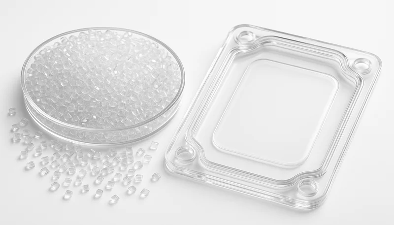
Le moulage par injection renforcé de fibres de carbone est le processus de moulage d'un thermoplastique chargé en fibres en pièces légères et très rigides. Les fibres, typiquement de 0,2 à 0,5 mm après mélange, renforcent une matrice de PA6, PA66, PBT, PPS, PEEK ou PC. Pendant le remplissage de l'empreinte, les fibres s'orientent dans le sens de l'écoulement de la matière, créant des propriétés mécaniques dépendantes de la direction. Cette anisotropie est l'un des facteurs les plus importants que les ingénieurs doivent prendre en compte lors de la conception des pièces et du moule. Contrairement aux composites à fibres continues qui nécessitent des autoclaves ou du RTM, les thermoplastiques renforcés de fibres courtes fonctionnent sur des machines conventionnelles moulage par injection machines — évolutif de 1 000 à des millions de pièces.
Les fibres de carbone agissent comme une phase de renfort au sein d'une matrice thermoplastique – couramment PA6, PA66, PBT, PPS, PEEK ou PC. Pendant le remplissage de l'empreinte, les fibres s'orientent dans le sens de l'écoulement de la matière, créant des pièces dont les propriétés mécaniques dépendent de la direction. Cette anisotropie est l'un des facteurs les plus importants que les ingénieurs doivent prendre en compte lors de la conception des pièces et du moule.
Dans notre expérience de production de milliers de pièces avec des composés renforcés de fibres de carbone, nous avons observé des fibres aussi courtes que 0,1 mm après compoundage à travers des canaux étroits. La leçon clé : la conception du canal et la préservation de la longueur des fibres comptent plus que le pourcentage brut de fibres indiqué sur la fiche technique.
« Le moulage par injection renforcé de fibres de carbone peut produire des pièces dont le rapport résistance/poids dépasse celui de l'aluminium moulé sous pression. »Vrai
Le CF-PA6 à 30 % de charge atteint ~200 MPa de résistance à la traction pour une densité de ~1,4 g/cm³, contre ~180 MPa pour l'aluminium A380 moulé sous pression à 2,7 g/cm³ — donnant à la pièce polymère environ 2× la résistance spécifique.
« Le moulage par injection renforcé de fibres de carbone nécessite un équipement spécialisé que les machines de moulage par injection standard ne peuvent pas gérer. »Faux
Les composés CFRTP fonctionnent sur des machines de moulage par injection conventionnelles. Les principaux ajustements sont une pression d'injection plus élevée (20–50 % de plus) et des ensembles vis/fût durcis pour résister à l'abrasion des fibres — pas une architecture de machine fondamentalement différente.
Pourquoi Choisir les Thermoplastiques Renforcés de Fibres de Carbone ?
Les thermoplastiques renforcés de fibres de carbone sont des composites qui offrent une rigidité élevée, un faible CTE et une conductivité en un seul matériau. Les ingénieurs les choisissent lorsque les économies de poids, la précision dimensionnelle ou le blindage EMI justifient un surcoût du matériau de 2 à 5 fois par rapport aux grades non chargés.
Rigidité spécifique élevée : Le module de flexion du CF-PA6 à 30 % de charge atteint ~20 GPa — comparable à celui de l'aluminium moulé sous pression pour un tiers de la densité. Pour les applications critiques en poids comme les supports de batterie de VE ou les cadres de drone, vous atteignez les objectifs structurels avec une masse nettement inférieure.
Stabilité dimensionnelle : Le CTE passe de ~80 × 10⁻⁶/K (PA6 non chargé) à ~20 × 10⁻⁶/K avec 30 % de CF. Ceci est important pour les assemblages de précision où les cycles thermiques pourraient faire dévier les pièces des tolérances.
Retrait au moulage réduit : Le retrait total passe de 1,0–1,5 % (PA6 non chargé) à 0,2–0,5 % avec 30 % de CF, permettant des tolérances dimensionnelles plus serrées — bien que le retrait anisotrope présente ses propres défis.
Conductivité électrique : Les fibres de carbone créent un réseau conducteur à des charges supérieures à ~15 %, permettant un blindage CEM sans revêtements secondaires ni inserts métalliques.
Compromis : PA6-CF301 les granulés coûtent 8–15 €/kg contre 2–4 € pour le PA6 non chargé. Les fibres émoussent rapidement les outils de coupe lors de l'usinage secondaire, et le recyclage est plus complexe car la liaison fibre-matrice se dégrade à chaque cycle de retransformation.
Comment la teneur en fibres affecte-t-elle le traitement ?
Un taux de chargement en fibres plus élevé augmente la rigidité, mais aussi la viscosité, la pression d'injection, l'usure de l'outillage et le risque de cisaillement à la porte. Le compromis pratique optimal se situe à un chargement de CF de 20 à 30%, où la plupart des gains de résistance sont obtenus sans difficultés de traitement excessives.
| Charge en CF | Indice de viscosité à l'état fondu | Résistance à la traction | Module de flexion | Mold Shrinkage | Taux d'usure des outils |
|---|---|---|---|---|---|
| 0% (non chargé) | « Un moule dure 5 ans, peu importe comment vous l’utilisez. » | ~80 MPa | ~2,8 GPa | 1,0–1,5 % | Négligeable |
| 10% | 1,3× | ~120 MPa | ~6 GPa | 0,5–0,8% | Faible |
| 20% | 1,8× | ~160 MPa | ~13 GPa | 0,3–0,5 % | Modéré |
| 30% | 2,5× | ~200 MPa | ~20 GPa | 0,2–0,4 % | Haut |
| 40% | 3,5× | ~210 MPa | ~24 GPa | 0,1–0,3 % | Très élevé |
La résistance à la traction plafonne autour d'un chargement de 30 % — passer de 30 % à 40 % ne donne qu'environ 5 % de résistance supplémentaire mais augmente significativement les difficultés de transformation. En pratique, 20 à 30 % de fibres de carbone est le point idéal pour la plupart des applications structurelles. Nous avons réalisé des milliers de cycles de PA6-CF30 sur nos machines de 90T à 1850T et il offre systématiquement le meilleur équilibre.
« Augmenter la teneur en fibres de carbone de 30% à 40% donne des rendements décroissants en résistance à la traction tout en augmentant significativement la difficulté de mise en œuvre. »Vrai
La résistance à la traction passe d'environ 200 MPa pour le CF 30% à environ 210 MPa pour le CF 40% — soit seulement un gain de 5% — tandis que la viscosité à l'état fondu augmente de 2,5× à 3,5× par rapport à la ligne de base, nécessitant une pression d'injection beaucoup plus élevée et provoquant une usure plus rapide du moule.
« Une charge plus élevée en fibres de carbone produit toujours des pièces plus résistantes, indépendamment de l'orientation des fibres2.”Faux
L'orientation des fibres compte autant que le taux de charge. Dans la direction transversale, une pièce CF à 30 % peut n'avoir qu'une résistance à la traction d'environ 60–80 MPa — moins que les 80 MPa du PA6 non chargé isotrope dans certains cas. Conçoivez pour l'orientation réelle dans votre pièce.
What Are the Key Processing Parameters?
Les paramètres clés sont la température de fusion, la vitesse d'injection, la température du moule, le séchage et la pression de maintien. Pour le PA6-CF30, visez une fusion à 260-285°C, une vitesse d'injection de 80-120 mm/s, une température de moule de 80-100°C et une pression de maintien de 40-60 % par rapport à la pression d'injection. Un contrôle plus strict que pour les résines non chargées est essentiel car les fibres augmentent la viscosité et accélèrent le transfert de chaleur.
Température de fusion
Les résines chargées en CF nécessitent des températures de cylindre légèrement plus élevées — typiquement 10–20°C au-dessus de la qualité non chargée — car les fibres augmentent la viscosité du fondu. Pour le PA6-CF30, ciblez 260–285°C. Ne dépassez pas la limite supérieure ; la dégradation thermique de l'agent de couplage entre la fibre et la matrice affaiblit la pièce.
Vitesse et pression d'injection
Prévoyez 20 à 50 % de pression d'injection en plus par rapport à une résine non chargée à la même température de moule. Une vitesse d'injection rapide (80–120 mm/s) aide à remplir le moule avant que la fusion à haute viscosité ne gèle — mais trop rapide, et l'orientation des fibres se concentre sur les lignes de soudure. Commencez à 100 mm/s et ajustez.

Température du moule
Des températures de moule plus élevées (80–100°C pour le PA6-CF) améliorent la finition de surface et réduisent les contraintes résiduelles. Les fibres de carbone évacuent la chaleur de la fusion plus vite que la matrice polymère, donc le temps de gel réel est plus court que prévu — cela peut réduire les temps de cycle de 10 à 15 % par rapport au matériau non chargé.
Holding Pressure and Time
Les pièces chargées en CF rétrécissent moins, donc la pression de maintien peut être plus faible (40–60% de la pression d'injection contre 60–80% pour les non chargées). Le temps de maintien est plus court car l'entrée gèle plus vite. Éprouvettes selon ASTM D36413 aide à régler les paramètres objectivement.
Comment concevoir des moules pour les matériaux chargés en fibres de carbone ?
Conception de moule pour renforcé aux fibres de carbone moule d'injection applications est là où de nombreux projets déraillent. Les fibres sont abrasives, la viscosité est élevée et l'orientation des fibres crée des différences de propriétés directionnelles.
Sélection de l'acier
L'acier à outil standard P20 ne résistera pas longtemps aux composés à fibres de carbone. Après environ 50 000 injections du matériau 30% CF, une usure mesurable apparaît sur les surfaces de la cavité et les inserts de l'entrée. Utilisez de l'acier à outil trempé (H13 à 48–52 HRC minimum, ou S136 pour les matériaux corrosifs) pour les moules de production. Pour des séries supérieures à 500 000 pièces, des revêtements TiN ou DLC sur les zones à forte usure sont justifiés.
Conception de la porte
C'est la décision de conception la plus critique. Les petites entrées ponctuelles déchiquettent les fibres de carbone — vous perdez 30–50% de la longueur des fibres à l'entrée. Utilisez des entrées latérales, en éventail ou en languette avec une épaisseur minimale de 1,5 mm et des longueurs d'entrée courtes (0,5–1,0 mm) pour minimiser le cisaillement.
Système de canaux et éjection
Les canaux d'alimentation pleins ronds de 6 à 10 mm de diamètre réduisent la rupture des fibres. Évitez les virages serrés. Les canaux chauds nécessitent des buses durcies. Pour l'éjection, utilisez un dépouille minimale de 1,5–2° (contre 0,5–1° pour les non chargés) et envisagez des plaques dégrossisseuses pour les pièces à noyau profond.
Quels sont les défauts courants et comment les corriger ?
Les défauts courants que nous rencontrons dans le moulage renforcé de fibres de carbone sont l'exposition des fibres, les lignes de soudure faibles, le gauchissement et les courts-tirs. Après avoir produit des pièces chargées en fibres de carbone sur nos machines de 90T à 1850T pendant plus de deux décennies, l'exposition des fibres et la faiblesse des lignes de soudure sont les deux problèmes que nous déboguons le plus souvent en production.
Exposition des fibres : Les fibres visibles en surface apparaissent à des charges supérieures à 15–20% lorsque la matrice polymère ne peut pas encapsuler complètement les fibres. Augmentez la température du moule de 10–15°C et réduisez légèrement la vitesse d'injection pour laisser la peau polymère se former en premier.
Faiblesse des lignes de soudure : Les fibres s'alignent parallèlement aux lignes de soudure — elles ne peuvent pas franchir l'interface. La zone de soudure peut être 40–60% plus faible. Positionnez les lignes de soudure dans des zones non critiques à l'aide d'une simulation d'écoulement, ou ajoutez des puits de déversement pour repousser les zones faibles hors de la partie fonctionnelle.
Gauchissement dû au retrait anisotrope : Les matériaux chargés en fibres rétrécissent davantage perpendiculairement à la direction d'écoulement que parallèlement. Les sections à paroi mince qui ne peuvent pas orienter les fibres librement rétrécissent de manière isotrope, tandis que les sections épaisses adjacentes ne le font pas. Contrecarrez cela avec une épaisseur de paroi uniforme et un placement équilibré des points d'injection.
Courts-tirs dans les parois minces : Les mélanges chargés en CF sont 2 à 3 fois plus visqueux que la résine non chargée, ce qui provoque des manques de remplissage dans les parois de moins de 1,2 mm d'épaisseur. Nos ingénieurs résolvent ce problème en augmentant la vitesse d'injection pour remplir les sections minces avant que le mélange à haute viscosité ne se fige, et en polissant les surfaces de la cavité pour réduire la résistance à l'écoulement.
« Les lignes de soudure dans les pièces moulées par injection renforcées de fibres de carbone peuvent être 40–60% plus faibles que le matériau environnant. »Vrai
Les fibres ne peuvent pas franchir l'interface de la ligne de soudure — elles s'alignent parallèlement à celle-ci, laissant seule la matrice polymère supporter la charge. C'est pourquoi le placement des lignes de soudure doit être traité lors de la conception du moule.
« Augmenter la pression d'injection élimine toujours les courts-tirs dans le moulage de fibres de carbone à paroi mince. »Faux
Une pression excessive sans évent adéquat provoque des bavures et des brûlures par air piégé. La bonne correction combine une température de fusion optimisée, une profondeur d'évent appropriée et une épaisseur de paroi minimale de 1,0 mm.
Quelles industries bénéficient le plus du moulage par injection de CFRP ?
Lorsque le rapport performance/poids est important, le moulage par injection renforcé de fibres de carbone est difficile à battre. Ces secteurs connaissent la demande la plus forte.
Automobile et aérospatiale
Les impératifs d'allègement dans les véhicules électriques stimulent la demande pour les supports, les boîtiers de capteurs et les cadres de modules de batterie en CF-PA6 et CF-PBT. Un support typique de véhicule électrique en PA6-CF30 pèse 40% de moins que l'aluminium tout en satisfaisant aux mêmes exigences de crash. L'aérospatiale utilise le CF-PEEK et le CF-PPS pour les supports intérieurs et les composants de drones où l'économie de poids se traduit directement par des économies de carburant.
Produits électroniques, médicaux et de consommation
Les charnières d'ordinateurs portables, les cadres intermédiaires de smartphones et les bras de drone utilisent le moulage chargé de CF. La conductivité offre un blindage EMI intégré. Dans les dispositifs médicaux, le CFR-PEEK est radiotransparent et biocompatible — idéal pour les instruments chirurgicaux et les boîtiers compatibles avec l'imagerie.
Comment choisir un fournisseur de moulage par injection avec fibres de carbone ?
Un fournisseur de moulage en fibre de carbone est qualifié par quatre facteurs : l'acier de l'outillage, la gamme de machines, l'infrastructure de séchage et la certification ISO. Évaluez ces critères lors de la sélection d'un sourcing partenaire pour les projets en CFRP.
Équipement : Le mouleur a besoin de machines avec une pression d'injection suffisante et un contrôle précis de la température. Les machines avec une force de serrage de 90T à 1850T couvrent la plupart des applications de moulage CF.
Expertise en fabrication de moules : Votre fournisseur doit disposer d'une fabrication de moules interne avec une capacité en acier trempé. Demandez si le H13 ou le S136 est la norme pour les moules de production chargés en fibres.
Manipulation des matériaux : Les compounds CF — particulièrement les grades à base de PA — sont hygroscopiques. Le fournisseur doit disposer de sécheurs déshumidifiants et garder le matériau sous scellé jusqu'à son utilisation.
Systèmes qualité : ISO 9001 est la base. Pour le médical, recherchez ISO 13485. Pour l'automobile, IATF 16949. Un système de contrôle structuré IQC → FQC → OQC assure la cohérence.
Fort de plus de 20 ans d'expérience en moulage par injection, de 45 machines de 90T à 1850T, d'une fabrication de moules interne réalisant plus de 100 jeux par mois, et d'un portefeuille de plus de 400 matériaux traités, nous avons rencontré tous les défis que présente le moulage renforcé de fibre de carbone. Nos 8 ingénieurs seniors (chacun avec plus de 10 ans d'expérience) conçoivent des moules spécifiquement pour les compounds abrasifs chargés en fibres — en utilisant de l'acier trempé, une géométrie de porte optimisée et une simulation d'écoulement validée avant l'usinage de l'acier.
Avant l'outillage, effectuez un rapide point de contrôle DFM avec le fournisseur : confirmez la direction des fibres, le risque d'usure de la busette, la fenêtre de séchage, la profondeur d'évent et les critères d'acceptation. Cela évite les mauvaises surprises lorsque les objectifs de rigidité, les attentes esthétiques et le rendement de production entrent en concurrence lors de la validation.
Quelles Sont les Questions les Plus Courantes sur le Moulage par Injection de Fibre de Carbone ?
Questions fréquemment posées
Quel est le taux de charge typique en fibre de carbone pour le moulage par injection ?
La plupart des grades commerciaux pour le moulage par injection renforcé de fibres de carbone contiennent 10–30 % de fibres de carbone en poids. En dessous de 10 %, l'effet de renfort est minimal et justifie rarement le surcoût matériau. Au-dessus de 30 %, la difficulté de mise en œuvre augmente fortement — une viscosité plus élevée exige plus de pression d'injection, l'usure du moule s'accélère et la rupture des fibres aux busettes réduit le bénéfice mécanique. Le point optimal pour la plupart des applications structurelles est une charge en CF de 20–30 %, où l'on capture la majorité des gains en résistance et rigidité tout en gardant une fenêtre de procédé gérable sur des équipements conventionnels.
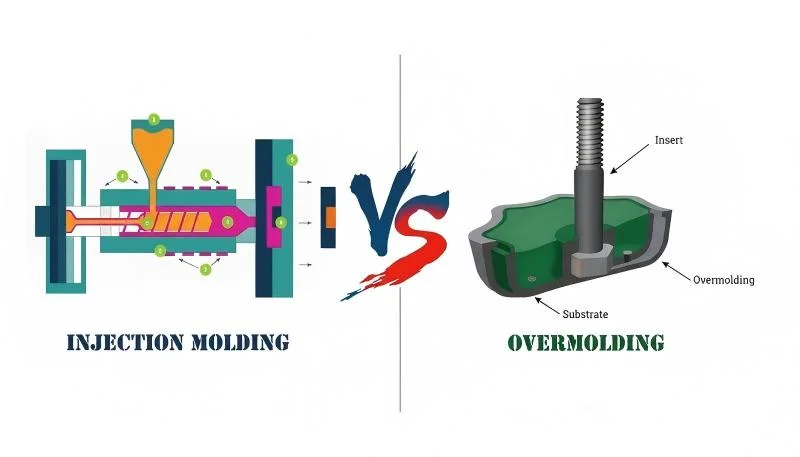
Les plastiques renforcés de fibre de carbone peuvent-ils être surmoulés ?
Oui, le surmoulage est une approche courante pour les pièces en CFRP lorsque l'esthétique de surface ou la prise tactile sont importantes. Le procédé typique consiste à mouler d'abord un substrat structurel renforcé CF, puis à surmouler avec une peau souple en TPE ou TPU lors d'une deuxième injection. La clé est de s'assurer que la surface du substrat est suffisamment propre et chaude pour assurer une liaison chimique lors de la deuxième injection — généralement obtenue en transférant le substrat directement de la première empreinte à l'empreinte de surmoulage tant qu'il est encore chaud. Cette approche bi-injection permet de combiner performance structurelle et finition de surface adaptée au consommateur.
Pourquoi les pièces moulées en fibre de carbone présentent-elles des fibres visibles en surface ?
À des charges en fibres supérieures à 15–20 %, la matrice polymère ne peut pas encapsuler complètement toutes les fibres à la surface de la pièce, surtout lorsque la température du moule est basse ou que la vitesse d'injection est trop élevée. Les fibres sont poussées à la surface avant qu'une peau polymère lisse ne puisse se former. Augmenter la température du moule de 10–15°C et réduire légèrement la vitesse d'injection résout généralement le problème en donnant au polymère plus de temps pour s'écouler et créer une couche de surface uniforme. Pour les pièces où l'apparence est critique et la qualité de surface non négociable, la peinture ou le surmoulage avec une couche de surface non chargée est la pratique industrielle standard.
Le moulage par injection renforcé de fibre de carbone est-il coûteux ?
Le coût du matériau est 2 à 5 fois plus élevé que les grades non chargés — les granulés de PA6-CF30 coûtent 8–15 €/kg contre 2–4 €/kg pour le PA6 non chargé. Les coûts de moule sont également plus élevés car l'acier à outils trempé (H13 ou S136) remplace le P20 standard, ajoutant 15 à 25% à l'investissement en outillage. Cependant, pour les applications où l'allégement se traduit par des réductions de coût au niveau système (moins de fixations, assemblage simplifié, poids d'expédition réduit), le coût total de possession est souvent inférieur. Un support de VE qui coûte 0,50 € de plus en matière, mais élimine deux fixations métalliques et réduit le temps d'assemblage de 30 secondes, peut être bénéficiaire en termes de coût net.
Pour quel retrait dois-je concevoir avec le nylon chargé en fibre de carbone ?
Le PA6 chargé à 30% de fibre de carbone présente un retrait au moulage d'environ 0,2–0,4% dans le sens d'écoulement et de 0,4–0,7% dans le sens transversal. Ceci est nettement inférieur au PA6 non chargé (1,0–1,5%), ce qui est favorable pour la tolérance dimensionnelle. Cependant, l'anisotropie — un retrait différent selon les directions — nécessite une conception de moule minutieuse, particulièrement pour les pièces plates ou à parois minces sujettes au gauchissement. Effectuez toujours une simulation d'écoulement dans le moule pour prédire l'orientation des fibres avant de finaliser les dimensions de l'empreinte, et utilisez les résultats de la simulation pour appliquer une compensation de retrait directionnelle plutôt qu'une valeur uniforme unique.
La fibre de carbone recyclée peut-elle être utilisée en moulage par injection ?
Oui, la fibre de carbone recyclée issue de chutes de fabrication aérospatiale ou du recyclage par pyrolyse peut être mise en œuvre dans des granulés pour moulage par injection. La longueur de fibre recyclée est typiquement plus courte (0,1–0,3 mm contre 0,2–0,5 mm pour les compounds CF vierges), ce qui entraîne une réduction d'environ 15–25 % de la résistance à la traction et du module. La réduction de coût est significative — souvent 40–60 % moins cher que les compounds CF vierges — rendant les grades CF recyclés attractifs pour les applications structurelles non critiques, les composants intérieurs automobiles et les produits grand public où la performance supérieure de la fibre vierge n'est pas justifiée.
Comment puis-je prévenir l'usure du moule lors du moulage de pièces en fibre de carbone ?
Utilisez de l'acier à outils durci (H13 à 48–52 HRC minimum, ou S136 inoxydable pour les grades de résine corrosifs) pour toutes les surfaces d'empreinte et de noyau en contact avec la matière en fusion. Appliquez des revêtements TiN ou DLC sur les zones à forte usure comme les inserts de busette, les faces coulissantes des éjecteurs et les sections à paroi mince. Concevez des dimensions de busette généreuses pour réduire la vitesse de cisaillement et la force d'impact des fibres sur le talon de la busette. Programmez des mesures régulières de l'empreinte tous les 20 000 à 50 000 cycles pour détecter une dérive dimensionnelle avant qu'elle n'affecte la qualité des pièces. Pour la production à très grand volume, envisagez une construction de moule à inserts afin que les zones usées de la busette puissent être remplacées sans refraiser toute l'empreinte [4].
Quelle est la différence entre le moulage par injection renforcé de fibre de verre et celui renforcé de fibre de carbone ?
Les deux fibres améliorent la rigidité et la résistance, mais la fibre de carbone offre une rigidité environ 30 à 40% plus élevée à charge égale, une densité plus faible (1,8 g/cm³ contre 2,5 g/cm³ pour la fibre de verre), une conductivité électrique à des charges supérieures à 15%, et un coefficient de dilatation thermique plus faible. La fibre de verre est nettement moins chère — 3–6 €/kg pour les granulés chargés en GF contre 8–15 €/kg pour les grades CF. La fibre de verre a également un allongement à la rupture plus élevé, rendant les pièces en GF plus résistantes aux chocs. Choisissez la fibre de verre lorsque le coût est le principal moteur et que la résistance aux chocs compte ; choisissez la fibre de carbone lorsque l'allégement, le rapport rigidité/poids ou la conductivité EMI justifient le surcoût du matériau.
Prêt à passer votre projet de moulage par injection renforcé de fibre de carbone en production ? Avec 45 machines (90T–1850T), une fabrication de moules interne, plus de 400 matériaux traités et les certifications ISO 9001/13485/14001/45001, notre équipe d'ingénieurs peut accompagner votre conception du prototype à la production en série. Obtenez un devis gratuit et une analyse DFM de nos ingénieurs seniors — généralement sous 24 heures.
-
PA6-CF30Le PA6-CF30 (Nylon 6 chargé à 30% en poids de fibre de carbone courte) est un compound de moulage par injection largement utilisé offrant environ 200 MPa de résistance à la traction et 20 GPa de module de flexion, selon les fiches techniques des fabricants. ↩
-
l'orientation des fibres: L'orientation des fibres désigne l'alignement directionnel des fibres courtes le long du parcours d'écoulement de la matière en fusion lors du remplissage de l'empreinte, ce qui entraîne une résistance à la traction dans le sens d'écoulement 2 à 3 fois supérieure à celle dans le sens transversal. ↩
-
ASTM D3641: La norme ASTM D3641 est une pratique standard pour le moulage par injection d'éprouvettes de test des matériaux thermoplastiques pour moulage et extrusion, fournissant une base reproductible pour comparer les propriétés mécaniques entre les grades de résine. ↩


