 Overslaan naar inhoud

- Rib thickness should be 40-60% of nominal wall
- Improper rib design causes flow hesitation and sink marks
- Base radius and draft angle affect both mold flow and cooling efficiency
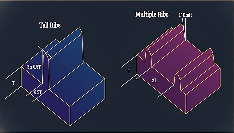
- Multiple thin ribs outperform single tall ribs for structural applications
- Moldflow simulation can predict rib defects before cutting steel
Rib design is one of the most consequential decisions in injection molding part engineering. A well-designed rib network adds stiffness without the weight and cost of a thicker wall—but get the geometry wrong, and you will fight flow hesitation1, zinkvlekken2, and cooling delays for the life of the mold. In our experience running production across hundreds of mold sets per month, rib-related defects are among the top five reasons parts get rejected at first article inspection. For a broader view of the process, our injection molding complete guide covers everything from material selection to production optimization.
This article examines how rib geometry—thickness, height, draft angle, base radius, and spacing—directly determines both the flow behavior of molten plastic through the cavity and the cooling efficiency of the finished part. Whether you are designing a new injection molded component or troubleshooting defects on an existing mold, understanding these relationships is essential for achieving consistent part quality and cost-effective production cycles.
What Are Ribs in Injection Molding and Why Do They Matter?
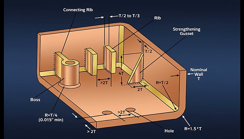
Ribs are thin, blade-like structural features that protrude perpendicularly from the nominal wall of an injection molded part. Their primary purpose is to increase bending stiffness and rigidity without proportionally increasing wall thickness, material consumption, or cycle time. In the context of mold flow, ribs act as auxiliary channels: they can either help distribute melt evenly across the part or cause the melt front to hesitate and freeze off, depending on their thickness relative to the nominal wall. For cooling, the T-junction where a rib meets the wall creates a localized thermal mass that cools more slowly than the surrounding steel, producing sink marks on the cosmetic surface opposite the rib.
If you are comparing vendors or planning procurement, our injection molding supplier sourcing guide covers RFQ prep, qualification, and commercial risk checks.
The fundamental tension is straightforward: make the rib too thin and it will not fill properly during injection; make it too thick and the intersection becomes a heat reservoir that drives sink marks, voids, and extended cycle times. The industry consensus range of 40% to 60% of nominal wall thickness balances both concerns. At our Shanghai factory, we have seen firsthand how engineers who push beyond 60% to hit stiffness targets invariably face sink mark rejections from the quality team. The correct approach is to use multiple thinner ribs rather than a single thick one—a strategy that maintains stiffness while keeping the thermal mass at each intersection manageable.
“Ideally, rib thickness should be maintained between 40% and 60% of the adjacent nominal wall thickness to prevent cosmetic defects.”Echt
Keeping ribs thinner than the main wall prevents excessive material accumulation at the intersection, significantly reducing the risk of sink marks and voids on the visible surface.
“Making a rib the same thickness as the main wall is the best way to maximize part strength without side effects.”Vals
Equal thickness creates a heavy mass at the intersection, leading to severe sink marks, internal voids, and significantly increased cooling times due to heat retention at the base.
What Are the Key Parameters for Rib Design Optimization?
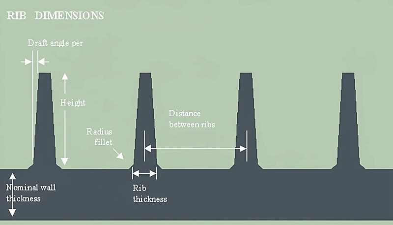
The key parameters are rib thickness, height, draft angle, base radius, and spacing. Each one independently affects how the melt flows through the cavity and how efficiently heat can be extracted from the tool. Getting even one of these wrong can cascade into filling defects, dimensional instability, or cosmetic failures that require expensive tooling modifications to fix. The table below summarizes each parameter, its recommended range, and its dual impact on flow and cooling.
| Parameter | Aanbevolen waarde | Impact on Mold Flow | Impact on Cooling |
|---|---|---|---|
| Rib Thickness (t) | 40% – 60% of Nominal Wall (T) | Thin ribs cause flow hesitation; thick ribs improve fill but risk defects | Thicker ribs increase local mass, requiring longer cooling to prevent sink marks |
| Rib Height (H) | No more than 3x Nominal Wall (T) | Excessive height raises injection pressure and can trap gas | Deep ribs are difficult to cool; heat gets trapped at the tip, causing warpage |
| Trekhoek | 0.5 to 1.5 degrees per side | Higher draft facilitates ejection but reduces effective tip thickness | Minimal direct impact, though insufficient draft causes drag marks |
| Base Radius (R) | 25% – 50% of Nominal Wall (T) | Generous radii reduce shear stress and pressure loss | Large radii increase inscribed circle at base, creating thermal hotspots |
| Spacing (Pitch) | At least 2x Nominal Wall (T) | Tight spacing creates race-tracking where flow accelerates around ribs | Crowded ribs create heat pockets the mold steel cannot dissipate effectively |
What Are the Advantages and Disadvantages of Rib Structures?
The main advantages are stiffness, cycle time reduction, and material savings. The main disadvantages are sink marks, flow hesitation, and increased tooling cost. The net benefit is strongly positive when geometry follows established guidelines, but the downside risk grows quickly when designers cut corners. Ribs increase stiffness without proportionally more material, and compared to solid walls of equivalent stiffness, ribbed designs cool faster. However, the rib-wall intersection is the single most common source of sink marks, thin ribs can cause flow hesitation, and deep ribs require expensive EDM3 tooling. Understanding this tradeoff is the foundation of good rib design.
| Voordelen | Nadelen |
|---|---|
| High Strength-to-Weight Ratio: Increases stiffness significantly without the material cost of a solid thick wall | Sink Marks: The rib-wall intersection is a primary location for surface depressions |
| Cycle Time Reduction: Ribbed designs cool faster than solid walls of equivalent stiffness | Flow Hesitation: Thin ribs can cause the melt front to freeze before filling the feature |
| Warp Resistance: Strategic rib placement disrupts residual stress patterns | Venting Challenges: Deep ribs create dead ends for gas, risking burn marks (Diesel effect) |
| Material Savings: Reduces polymer consumption compared to thicker global walls | Tooling Complexity: Deep ribs require EDM, increasing mold cost and lead time |
In our Shanghai factory, we run 47 injection molding machines ranging from 90T to 1850T, and our 8 senior engineers routinely review rib designs during DFM (Design for Manufacturability) analysis. The most common issue we flag is not the rib geometry itself—it is the lack of adequate venting provisions at rib tips. A rib that fills and traps gas will produce a burn mark on every single shot, and the only fix is a tooling modification. Catching this during the design review phase saves both time and money. Our in-house mold manufacturing facility, capable of producing 100+ mold sets per month, allows us to iterate on rib geometry quickly when fill simulation shows problems.
Where Are Rib Designs Most Commonly Applied?
Ribs are used across five primary industry categories: automotive, consumer electronics, power tools, battery systems, and appliances. Each application imposes different demands on rib geometry, material selection, and cosmetic requirements. Automotive structural parts like door panels and bumpers use ribs in PP or PA to achieve stiffness targets at minimum weight. Consumer electronics housings in PC/ABS rely on ribs for drop-test performance. Power tool casings use glass-fiber reinforced ribs for high-rigidity handles. Battery enclosures use rib grids to resist thermal warpage. Appliance internals use ribs for mounting features and structural brackets. A one-size-fits-all approach to rib design always fails because each application has unique flow, cooling, and cosmetic constraints.
“Adding a radius at the base of a rib reduces stress concentrations and aids material flow.”Echt
Fillets reduce the notch effect, improving impact strength, and smooth the flow path for the molten plastic, reducing shear stress at the intersection.
“Ribs cool faster than the nominal wall because they are thinner, so they require no special cooling considerations.”Vals
While the rib blade itself cools fast, the base intersection holds heat longer than the surrounding wall. Without proper core cooling, this hotspot causes cycle delays and sink marks.
How Should Engineers Optimize Rib Design for Flow and Cooling?
Optimization is a disciplined six-step process covering wall thickness, rib proportions, draft, cooling, simulation, and venting. Our engineering team considers simulation results non-negotiable before committing to production tooling, because the cost of running Moldflow is trivial compared to the cost of modifying a finished mold. The six steps below provide a systematic framework that works across all material types and part geometries.
Step 1 — Establish Nominal Wall Thickness (T): Determine the base wall thickness based on the material flow length ratio and structural requirements. This value anchors every subsequent rib dimension. For most engineering resins, a 2.0 to 3.0 mm nominal wall provides a practical starting point.
Step 2 — Calculate Rib Thickness (t): Apply t = 0.5 x T for high-gloss resins like PC/ABS, or up to t = 0.7 x T for low-shrinkage or textured materials. Never exceed 70% of the nominal wall—doing so virtually guarantees sink marks on the opposite surface. Our recommendation for visible cosmetic surfaces is to stay at or below 50% for maximum safety.
Step 3 — Set Draft and Height: Apply a minimum of 0.5 degrees draft per side. Calculate the resulting thickness at the rib tip—ensure it is not less than 0.75 mm to avoid venting issues and short shots. Limit total rib height to 3x the nominal wall. Taller ribs require disproportionate ejection force and are far more prone to sticking or damage during ejection.
“Flow hesitation occurs when the melt front advances through variable-thickness areas, preferring the path of least resistance.”Echt
The polymer melt prefers thick sections (low resistance) over thin ribs (high resistance). If the melt slows too much in the rib, it may freeze off before filling completely.
“Increasing injection speed is the only solution to fix short shots in deep ribs.”Vals
While speed helps, excessive speed causes jetting, gas burns, and flash. The correct solution involves optimizing rib thickness, gating location, and venting—not simply cranking up the injection velocity.
Step 4 — Plan Cooling at the Intersection: If ribs are deep or clustered, incorporate mold cooling channels (baffles or bubblers) directly into the core steel opposite the ribs. This is not optional for high-production molds—the cost of adding cooling elements during initial build is a fraction of the cost of modifying a production mold to fix cooling problems. The localized cooling at the rib base directly controls cycle time and sink mark severity.
Step 5 — Simulate Flow and Warp: Use Moldflow or equivalent CAE software to check for flow hesitation, weld line placement, and predicted warpage. This step catches problems that no rule-of-thumb can predict, especially in complex parts with multiple rib networks competing for flow. The simulation cost is trivial compared to the cost of a mold modification.
Step 6 — Verify Venting at Rib Tips: Ensure the matrijsontwerp allows for adequate venting at the end of every rib. Trapped air will superheat under compression pressure (the diesel effect), causing material degradation, burn marks, and even localized carbonization. In practice, this means grinding vent grooves (0.015 to 0.025 mm deep) at rib terminations on the parting line or adding vent pins for blind ribs. This is the single most commonly overlooked detail in rib design—we see it missed in roughly 30% of first-time DFM submissions.
What Role Does Material Selection Play in Rib Performance?
Material selection is the primary driver of rib design parameters because different polymers shrink, flow, and conduct heat at vastly different rates. Amorphous materials like PC and ABS require generous base radii to prevent stress cracking, while semi-crystalline materials like PP and PA have higher shrinkage that demands tighter thickness controls. With experience across 400+ plastic materials, our engineering team selects rib parameters based on the specific resin grade, not generic rules of thumb.
| Type materiaal | Shrinkage Behavior | Recommended Rib/Wall Ratio | Key Design Consideration |
|---|---|---|---|
| Amorphous (PC, ABS) | Low, isotropic | 50-60% | Requires generous base radii to prevent stress cracking |
| Semi-crystalline (PP, PA) | High, anisotropic | 40-50% | Higher shrinkage increases sink mark risk; use tighter ratio |
| Glass-filled (PA-GF, PBT-GF) | Lower shrinkage, but anisotropic | 50-65% | Fiber orientation at rib base affects strength and warpage |
| PC/ABS blends | Matig | 50-60% | Good balance of flow and rigidity; most forgiving for rib design |
| High-flow grades | Lower viscosity | 45-55% | Better fill in thin ribs but may show more visible sink marks |
“Glass-filled resins allow slightly higher rib-to-wall ratios because their lower shrinkage reduces sink mark severity.”Echt
The reduced volumetric shrinkage of glass-filled grades means the intersection contracts less during cooling, giving designers more latitude on rib thickness—typically up to 60-65% of the wall.
“All plastic materials respond the same way to rib geometry, so a universal thickness ratio works for every project.”Vals
Different polymers have dramatically different shrinkage rates, thermal conductivities, and flow behaviors. A ratio that works perfectly for PP may cause severe sink marks in PC, and vice versa.
Veelgestelde vragen
Veelgestelde vragen
Why Do Ribs Cause Sink Marks on the Visible Surface?
Sink marks appear on the cosmetic surface (A-side) opposite a rib because the rib-wall intersection contains significantly more material volume than the surrounding wall. As this concentrated mass cools and shrinks during the molding cycle, it pulls the still-soft outer skin inward, creating a visible depression. Maintaining rib thickness below 60% of the nominal wall and ensuring adequate localized cooling at the intersection are the most effective countermeasures. For critical cosmetic surfaces, we recommend staying at or below 50% to eliminate visible sink entirely. Gas-assist molding and foaming agents can also reduce sink severity in challenging applications.
What Is Flow Hesitation in Ribbed Parts?
Flow hesitation is a filling defect that occurs when the polymer melt front encounters a thin rib entrance and elects to flow through the thicker adjacent wall instead, which presents lower flow resistance. As the melt continues to advance elsewhere, the material at the rib entrance begins to cool and increase in viscosity. If the viscosity rises too high before the rib fills, the material freezes off entirely, resulting in a short shot. Proper rib thickness (within the 40-60% range), strategic gate placement near rib networks, and adequate injection speed all help mitigate this common defect. Moldflow simulation is the most reliable way to predict hesitation before cutting steel.
How Does Material Selection Affect Rib Design Parameters?
Material choice fundamentally changes the rib design equation. Amorphous materials like Polycarbonate (PC) and ABS require generous base radii to prevent stress cracking at the rib-wall junction, and they tend to be more forgiving on sink marks due to lower shrinkage. Semi-crystalline materials like Polypropylene (PP) and Polyamide (PA) have higher volumetric shrinkage during crystallization, making them significantly more susceptible to sink marks and demanding tighter thickness ratios (often below 50%). Glass-filled grades allow slightly higher rib-to-wall ratios because the fiber content reduces overall shrinkage. Always select rib parameters based on the specific resin grade rather than generic guidelines.
Can Ribs Replace Solid Wall Thickness Entirely?
Yes, in many structural applications, replacing a thick solid wall with a thinner wall reinforced by a network of ribs is standard practice. This approach, called coring out, reduces part weight, material consumption, and cycle time while maintaining comparable bending stiffness. The critical constraint is designing the rib network to carry the expected loads without introducing molding defects—each rib must stay within the 40-60% thickness ratio, maintain adequate spacing (at least 2x wall thickness apart), and include proper draft for ejection. Our engineering team routinely evaluates coring-out proposals during DFM review to ensure the structural and manufacturing tradeoffs are balanced correctly.
What Is the Inscribed Circle Method for Rib Design?
The inscribed circle method is a design verification technique where an engineer draws the largest possible circle that fits within the rib-wall intersection cross-section. The diameter of this circle directly represents the local thermal mass—the larger the circle, the more material is concentrated at the junction, and the longer it takes to cool. The goal is to minimize this inscribed circle diameter relative to the nominal wall thickness. A practical target is to keep the inscribed circle diameter no larger than 1.2x the wall thickness, which ensures uniform cooling and minimizes the severity of sink marks on the opposite surface.
How Many Ribs Should You Use Instead of One Thick Rib?
Multiple thinner ribs spaced at least 2x the wall thickness apart outperform a single thick rib in virtually every scenario. This distributed approach spreads the structural load across several smaller intersections, each of which cools faster and produces less severe sink marks than one concentrated thermal mass. Multiple ribs also provide more uniform stiffness across the part and are less likely to cause warpage due to asymmetric shrinkage. The only situations where a single tall rib might be preferred are severely space-constrained designs, but even then, the manufacturing tradeoffs (longer cooling, worse sink marks, higher ejection force) usually argue against it.
What Happens If You Exceed the Recommended Rib Height?
Ribs taller than 3x the nominal wall thickness create a cascade of manufacturing problems. The rib tip becomes difficult to cool effectively, leading to extended cycle times and dimensional instability. Ejection force increases disproportionately with rib height, raising the risk of the rib sticking, cracking, or deforming during part removal. Deep ribs also trap gas more readily, requiring dedicated vent pins or porous steel inserts to prevent the diesel effect (burn marks from compressed, superheated air). In extreme cases, ribs exceeding the height limit require specialized mold features like lifters or side-action slides, which significantly increase tooling cost and maintenance requirements.
With over 20 years of injection molding experience and 47 machines in our Shanghai facility, our team of 8 senior engineers reviews rib designs daily during DFM analysis. Our in-house mold manufacturing capability means we can iterate on rib geometry quickly when simulation reveals flow or cooling issues—before committing to production tooling.
Ben je op zoek naar een expert DFM-review voor je ribdesign? Ons engineeringteam geeft gedetailleerde feedback over partgeometry, materiaalselectie en moldability voordat je tot tooling overgaat. Ontvang competitieve prijzen, simulatie-gebaseerde procesoptimalisatie en productietijdlijn van ZetarMold. Vraag een Gratis Offerte aan.
-
flow hesitation: flow hesitation verwijst naar een fenomeen in spuitgieten waarbij de meltfront vertraagt of stopt wanneer het een dunne sectie tegenkomt, wat mogelijk een short shot veroorzaakt. ↩
-
zinkvlekken: zinkmerken verwijzen naar oppervlakte-indrukkingen veroorzaakt door lokale krimp op dikke wandkruisingen, vooral gebruikelijk op rib-wandverbindingen in spuitgegoten onderdelen. ↩
-
EDM: Elektro-erosie (EDM) is een precisieproductieproces waarbij materiaal wordt verwijderd met gecontroleerde elektrische vonken, gebruikt om diepe ribholtes in gehard gereedschapsstaal te maken die niet met conventionele snijgereedschappen kunnen worden bewerkt. ↩


