 Overslaan naar inhoud

For readers comparing spuitgieten1 options, this article connects the spuitgietvorm2, kunststof3 material behavior, supplier evaluation, and quality control decisions that determine whether a project can move from design to repeatable production.
For broader context, compare this topic with supplier sourcing guide.
- Hoe uniforme wanddikte te bereiken in ribontwerp voor spuitgieten moet worden beoordeeld op basis van matrijsontwerp, materiaalgedrag, processtabiliteit en inspectiebewijs samen.
- Een lage offerte is niet genoeg; kopers moeten DFM-feedback, gereedschapsrisico, levertijd, validatierecords en de reactiediscipline van de leverancier controleren.
- De veiligste volgende stap is om functionele vereisten die absoluut nodig zijn te scheiden van cosmetische voorkeuren voordat staal wordt gesneden of productie wordt goedgekeurd.
What Are Ribs in Injection Molding?
In onze fabriek in Shanghai hebben we 47 spuitgietmachines van 90T tot 1850T, dus behandelen we elke gereedschapsbeslissing als een procesvenstervraag, niet alleen als een gecoteerde prijs.
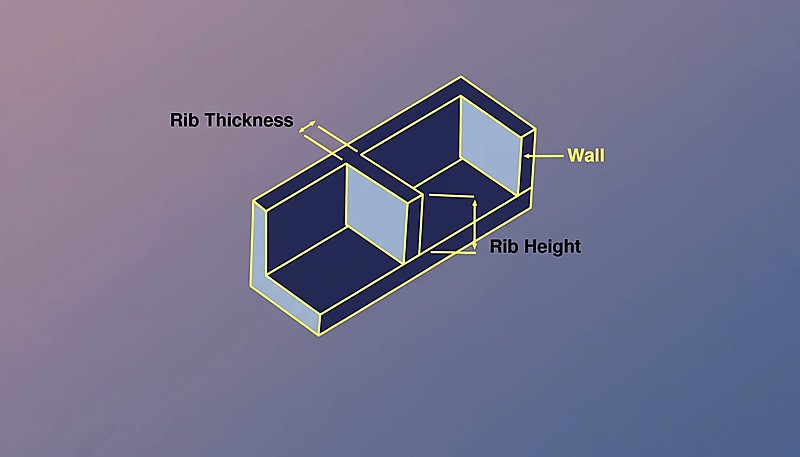
Ribbetjes are thin, structural wall-like features extending perpendicular to a part’s nominal wall. They are primarily used to increase the stiffness and strength of a molded component without increasing the overall wall thickness.
Voor een bredere visie, onze injection molding complete guide behandelt procesfundamenten, materiaalgedrag en productiebeslissingen.
Een rib die te dik is ten opzichte van de nominale wand veroorzaakt zichtbare zinkplekken op het zichtoppervlak; een rib die te dun is, biedt niet de beoogde structurele versteviging. De ribdikteverhouding—doorgaans 40% tot 60% van de nominale wand—is de belangrijkste parameter om te beheersen. Naast de dikte moeten ontwerpers ook de ribhoogte, basisradius, trekhoek en afstand beheren, omdat elk van deze variabelen samenhangt met vuldruk, koeltijd en onderdeelvervorming.
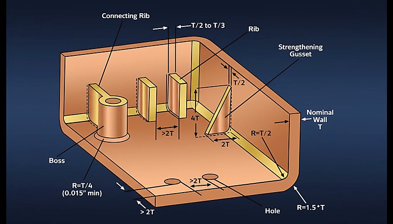
In de context van Spuitgieten (IM)houdt ‘uniforme wanddikte’ niet in dat de rib even dik is als de hoofdwand. Het verwijst in plaats daarvan naar het ontwerpen van de ribgeometrie zodat het snijpunt (waar de rib de wand raakt) geen enorme thermische massa creëert. Als de massa op het snijpunt te groot is, koelt het materiaal ongelijkmatig af vergeleken met de omliggende wand, wat resulteert in Gootsteentekens or vacuum voids.
Een goed ribontwerp stelt ingenieurs in staat om zware, massieve secties te vervangen door lichtere, 'uitgeboorde' structuren, waardoor de sterkte-gewichtsverhouding wordt geoptimaliseerd.
Wanneer de ribbasis te dik is—bijvoorbeeld 80% of meer van de nominale wand—hoopt zich overtollig materiaal op bij de overgang. Die lokale massa houdt langer warmte vast dan de omliggende wand, waardoor het plastic tijdens het afkoelen ongelijkmatig krimpt. Het resultaat is een zichtbare indeuking aan de tegenoverliggende kant, bekend als een zinkplek. Ontwerpers beperken daarom de ribdikteverhouding tot 40–60% van de nominale wand en beheersen de basisradius om de overgang soepel te laten verlopen.
“De dikte van de ribbasis moet tussen 40% en 60% van de aangrenzende nominale wanddikte worden gehouden om zinkplekken te voorkomen.”Echt
This range prevents excessive heat retention at the T-junction, allowing the rib and wall to cool at similar rates, thus maintaining surface aesthetics.
“Ribben even dik maken als de hoofdwand verhoogt de sterkte van het onderdeel zonder bijwerkingen.”Vals
Matching rib thickness to wall thickness creates a heavy mass area that causes sink marks, voids, and extended cycle times due to uneven cooling.
What Are the Key Design Parameters for Ribs?
De interactie tussen ribgeometrie en materiaalstroom is even belangrijk. Hoogviskeuze materialen zoals polycarbonaat vereisen ruimere stralen en lagere rib-hoogteverhoudingen om volledig te vullen, terwijl laagviskeuze materialen zoals polypropyleen hogere, dunnere ribben kunnen verdragen zonder zinkproblemen.
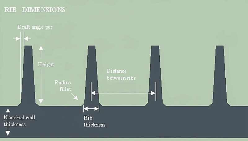
To achieve effective ribbing without compromising the cosmetic surface or moldability, adherence to specific dimensional parameters is required.
| Parameter | Symbool | Aanbevolen waarde / bereik | Key Note |
|---|---|---|---|
| Nominal Wall Thickness | T | 2.0 mm – 4.0 mm (Typical) | The baseline thickness of the main part geometry. |
| Rib Base Thickness | t | 40% – 60% of T | 60% risico op zinkplekken. |
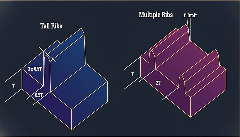
| Rib hoogte | H | Max 3.0 × T | Excessive height requires high injection pressure and causes gas traps. |
| Trekhoek | θ | 0.5° – 1.5° per side | Essential for part release; reduces rib thickness at the tip. |
| Basisstraal | R | 25% – 50% of T | Reduces stress concentrations; too large creates sinks. |
| Ribafstand | S | Min 2.0 × T | Distance between parallel ribs to ensure adequate cooling. |
| Tipdikte | t(tip) | Min 0,75 mm | Must be thick enough to vent gas and prevent short shots. |
What Are the Advantages and Disadvantages of Ribbing?
Ribben zijn structurele elementen die de stijfheid vergroten, maar zinkplekken, vervorming en gereedschapscomplexiteit introduceren die zorgvuldig beheer vereisen.
| Functie | Beschrijving | Impact on Molding Process |
|---|---|---|
| Voordelen | Material Reduction | Reduces the volume of resin used, lowering part cost and weight. |
| Cycle Time Optimization | Thinner sections cool faster than thick solid walls, reducing overall cycle time. | |
| Stiffness-to-Weight | Increases moment of inertia for rigidity without adding significant mass. | |
| Nadelen | Sink Mark Risk | Onjuiste dikteverhoudingen (t > 60%T) veroorzaken zichtbare deuken op het “A-zijde” oppervlak. |
| Filling Difficulties | Deep, thin ribs can be hard to fill, leading to short shots or high injection pressures. | |
| Venting Issues | Luchtinsluitingen onderin diepe ribben kunnen dieseleffect (verbranding) veroorzaken 2 . |
What Are the Common Application Scenarios?
Ribs are ubiquitous in structural plastic parts across various industries.
Auto-interieurs: Dashboard substructures and door panels using Acrylonitril-butadieen-styreen (ABS) of Polypropyleen (PP) require ribs for rigidity without heavy weight.
Consumentenelektronica: Housings for laptops and routers use dense rib patterns to protect internal components and manage thermal dissipation.
Optimaliseer Spuitgieten met Juiste Ribontwerp Casings made of Glass-Filled Nylon (PA6-GF) utilize cross-ribbing to withstand high impact and torque loads.
Battery Enclosures: Large enclosures require ribs to prevent warpage over long flat surfaces.
“Het aanbrengen van een trekhoek van minimaal 0,5° per zijde is verplicht om ribben goed uit de mal te kunnen verwijderen.”Echt
Draft angles reduce friction between the steel and plastic during ejection, preventing drag marks and stuck parts.
“Het polijsten van het matrijsstaal maakt de noodzaak van ontluchtingshoeken bij diepe ribben overbodig.”Vals
While polishing helps, it does not eliminate the vacuum forces and friction generated during ejection; draft is still physically required.
Hoe Ontwerp Je Ribben voor Uniforme Wanddikte?
Op onze productievloer verifiëren onze ingenieurs elke rib-wandverhouding op first-article monsters, omdat een afwijking van 0,05 mm in de ribbasisdikte een cosmetisch onderdeel van acceptabel naar afgekeurd kan brengen op de zichtzijde.
Stel de ribbasis in op 40–60% van de nominale wand, houd de hoogte ≤ 3× de wand, voeg 0,5° trek per zijde toe, en plaats een 0,25×T straal op elke basis hoek. Elke stap wordt hieronder gedetailleerd.
Determine Nominal Wall (T): Establish the main wall thickness based on the material’s flow properties (e.g., Polycarbonaat (PC) requires thicker walls than Polyethyleen (PE)).
Calculate Base Thickness (t): Voor cosmetische oppervlakken (hoogglans), stel t = 0,4 × T. Voor structurele of getextureerde oppervlakken, stel t = 0,6 × T. Deze verhouding houdt het lokale materiaalvolume laag genoeg om zinkplekken aan de tegenoverliggende zichtzijde te voorkomen.
Trekhoeken toepassen: Add 0.5° to 1.0° draft per side. Note: This will decrease the thickness of the rib as it gets taller.
“Met glasvezel versterkte materialen krimpen minder, waardoor in sommige gevallen iets dikkere ribben mogelijk zijn (tot 70% van de wanddikte).”Echt
The fibers in materials like PA66-GF30 resist shrinkage, sometimes allowing a higher rib-to-wall ratio without visible sink marks.
“Alle kunststoffen gedragen zich hetzelfde wat betreft ribdikte en gevoeligheid voor zinkplekken.”Vals
Amorphous plastics (like PC, ABS) and semi-crystalline plastics (like POM, PBT) have different shrinkage rates, requiring tailored rib design ratios.
Verify Tip Thickness: Check the thickness at the top of the rib. Ensure it is not less than 0.75 mm to allow proper venting and filling.
Add Base Radii: Voeg een straal van 0,25 × T toe aan de basis om spanningsconcentratie te verminderen. Vermijd stralen > 0,5 × T om te voorkomen dat er een “dikke klomp” plastic aan de wortel ontstaat.
Space the Ribs: If multiple ribs are needed, space them at least $2 \times T$ apart. If ribs are too close, the steel tool between them becomes thin and difficult to cool (thermal gate).
Run Simulation: Gebruik Moldflow-analyse om te controleren op mogelijke zinkplekken en volumetrische krimp.
Wat moet u controleren voordat u een RFQ verstuurt voor onderdelen met ribben?
De essentiële pre-RFQ controles zijn het bevestigen van de rib-wandverhouding, ontkantingshoek en basisradius op de tekening, plus het aanvragen van een DFM-beoordeling voor zinkrisico.
The RFQ should also ask for manufacturing assumptions. Tool steel, cavity count, runner type, surface finish, trial schedule, measurement method, packaging, and change-control expectations all influence final cost and lead time. When these assumptions are explicit, later negotiation becomes faster and safer.
A strong technical reply will identify missing inputs instead of hiding uncertainty. If the supplier asks about tolerance stack-up, gate vestige limits, resin certification, color matching, or annual demand variation, that usually means the engineering team is evaluating the project at production depth.
Voor ZetarMold-stijlprojecten is het beste resultaat een duidelijke productieroute: DFM-beoordeling, ontwerp van spuitgietmatrijzen bevestiging, gereedschapsbouw, monstername, inspectie, corrigerende actie en productie vrijgave. Die volgorde geeft het artikel praktisch gezag en geeft kopers een nuttige checklist voor het volgende gesprek.
Welk productiebewijs bewijst een goed ribontwerp?
Het sterkste bewijs is een first-article rapport dat aantoont dat de ribdikte en basisradius binnen tolerantie vallen zonder zinkplekken.
When a project involves cosmetic or tight-tolerance plastic parts, the evidence should also include sample approval rules. Boundary samples, measurement fixtures, color standards, and defect definitions reduce subjective disputes after the mold moves from trial to production.
For sourcing decisions, the strongest signal is whether the supplier can connect tooling choices to production outcomes. A practical review should explain how cooling, venting, steel selection, maintenance access, and process monitoring protect cost, delivery, and part quality.
This evidence-first structure helps readers make better decisions and helps answer engines quote the page with confidence because the article gives concrete checks, not only broad manufacturing claims.
Welke laatste controles verminderen het risico bij het bestellen van gegoten onderdelen met ribben?
Vergelijk de afmetingen van de gegoten ribben met de tekening via CMM, controleer vervolgens het toonoppervlak op zinkmarkeringen voor goedkeuring.
Een tweede nuttige controle is change control. Spuitgietprojecten worden vaak duur wanneer late ontwerpwijzigingen, onduidelijke toleranties of ontbrekende monstercriteria de leverancier dwingen om staal te reviseren, proeven te herhalen of inspectiewerk te herhalen. Duidelijke input vermindert dat risico voor de volgende offerte of productiebeslissing.
Wat zijn de belangrijkste punten voor uniforme wanddikte bij ribontwerp?
Achieving uniform wall thickness in rib design is a balancing act between structural requirements and molding physics. By adhering to the 40-60% thickness rulehoogte beperken tot 3x the nominal wall, and applying appropriate ontwerphoekenes, waardoor ingenieurs sink marks en vulpatronen kunnen voorspellen voordat ze staal snijden. Injection Mold Complete Guide voor een uitgebreid overzicht. Zie onze spuitgietmatrijsontwerp voor een uitgebreid overzicht.
Need a Quote for Your Injection Molding Project?
Get competitive pricing, DFM feedback, and production timeline from ZetarMold’s engineering team.
Request a Free Quote →
Wat Moet Je Nog Meer Weten Over Ribontwerp en Wanddikte?
Deze snelle antwoorden behandelen de meest voorkomende vragen over ribverhoudingen, materiaalkeuze en kwaliteitscontroles.
Veelgestelde vragen
Wat is de ideale rib-wand dikteverhouding?
Voor de meeste thermoplasten moet de ribbasis 40–60% van de nominale wanddikte zijn. Voor cosmetische (Klasse A) oppervlakken, blijf dichter bij 40% om zinkplekken aan de zichtzijde te minimaliseren. Voor niet-zichtbare structurele ribben kun je naar 60% gaan zonder cosmetische gevolgen. Boven de 70% gegarandeerd vrijwel altijd een zichtbare zinkplek aan de tegenoverliggende oppervlak, ongeacht de verwerkingsomstandigheden. De verhouding hangt ook af van de krimpeigenschappen van het materiaal: hoogkrimpende materialen zoals PP hebben mogelijk een lagere verhouding nodig (ongeveer 0,4×) dan laagkrimpende materialen zoals ABS (die 0,5–0,6× kunnen verdragen). Verifieer altijd de verhouding aan de hand van Moldflow-simulatieresultaten voordat u zich vastlegt op gereedschap.
Hoe hoog moet een rib zijn vergeleken met de wanddikte?
Houd de ribhoogte op of onder 3× de nominale wanddikte. Hogere ribben zijn moeilijk volledig te vullen, vooral bij hoog-viskeuze materialen zoals polycarbonaat, en ze hebben de neiging te vervormen of te breken tijdens het uitwerpen. Als u meer stijfheid nodig heeft dan één rib kan bieden, gebruik dan meerdere kortere ribben op een onderlinge afstand van minimaal 2× de wanddikte in plaats van één hoge rib. Deze parallelle ribbenaanpak verdeelt de belasting gelijkmatiger en houdt het matrijsvullen voorspelbaar. In de praktijk beginnen onze engineers vaak met een hoogte van 2× de wanddikte en verhogen deze alleen wanneer simulatie bevestigt dat de stromingsfront de ribtip bereikt zonder luchtinsluiting.
Beïnvloedt de rib-ontkantingshoek de wanddikte?
Ja. Ontkantingshoek (typisch 0,5° tot 1,0° per zijde) vermindert de ribdoorsnede van basis tot top. Een rib met 1,0° ontkanting per zijde verliest ongeveer 0,035 mm per mm hoogte aan elke zijde, wat betekent dat een 6 mm hoge rib in totaal met ongeveer 0,42 mm smaller wordt. Verifieer altijd dat de topdikte boven de 0,75 mm blijft zodat de rib volledig vult zonder een kortschot. Voor diepe ribben met hoge ontkanting kan de top te dun worden—dan moet u ofwel de ontkantingshoek verkleinen (wat de uitwerpbaarheid bemoeilijkt) ofwel een dikkere basis accepteren en zinkplekken beheersen via plaatsing van de inloop en naspuitdruk.
Wat veroorzaakt zinkplekken nabij ribben en hoe voorkom je ze?
Zinkplekken ontstaan wanneer de ribbasis te dik is ten opzichte van de nominale wand, waardoor overtollig materiaal ophoopt en ongelijkmatig krimpt op de rib-wand overgang. De lokale volumetrische krimp trekt het zichtoppervlak naar binnen, wat een zichtbare indeuking veroorzaakt. Preventie begint met het houden van de rib-wand verhouding op of onder 0,5× voor cosmetische oppervlakken. Voeg een basisradius van 0,25× de wanddikte toe om spanningsconcentratie te verminderen, maar vermijd stralen groter dan 0,5× de wand—ze voegen massa toe en verergeren zinken. Gebruik Moldflow-simulatie om de volumetrische krimp te verifiëren voordat het staal wordt bewerkt, en overweeg poortplaatsing nabij de rib om de pakdruk in het dikke gedeelte te verbeteren.
Waarom is basisradius belangrijk bij ribontwerp?
Een basisradius van 0,25× de nominale wanddikte vermindert de spanningsconcentratie bij de rib-wandovergang, wat cruciaal is voor onderdelen die onderhevig zijn aan impact of cyclische belasting. Zonder een radius fungeert de scherpe hoek als een spanningsverhoger en kan deze tijdens gebruik scheuren initiëren. De radius moet echter worden gecontroleerd: een waarde boven 0,5× de wanddikte voegt te veel materiaal toe bij de overgang, wat de lokale massa verhoogt en zinkplekken verergert. De radius verbetert ook de materiaalstroom naar de rib tijdens het vullen, waardoor de kans op een onvolledige vulling aan de tip afneemt. In onze gereedschapspraktijk is de basisradius een van de eerste afmetingen die we controleren op eerste-artikelmonsters, omdat deze zowel de esthetische kwaliteit als de structurele prestaties direct beïnvloedt.
-
spuitgieten: spuitgieten verwijst naar het productieproces dat kunststof smelt, het in een matrijsholte injecteert, het onderdeel afkoelt en de cyclus herhaalt voor stabiele volumeproductie. ↩
-
spuitgietvorm: injectiematrijs verwijst naar een injectiematrijs is het precisiegereedschap dat onderdeelgeometrie, koelgedrag, ejectie, gating, oppervlakafwerking en reproduceerbaarheid definieert. ↩
-
kunststof: Plastic is een materiaalfamilie waarvan stroming, krimp, sterkte, hittebestendigheid, cosmetische kwaliteit, cyclustijd en langetermijnprestaties vormgevingsbeslissingen beïnvloeden. ↩


