 콘텐츠로 건너뛰기

- The four main cooling channel types for injection molds are straight-drill, baffle, spiral, and conformal.
- Cooling accounts for 70–80% of total cycle time — the single biggest lever for productivity.
- Conformal cooling reduces cycle time by 20–35% compared to straight-drill channels on complex geometries.
- Water is the most common coolant; oil is used for molds requiring temperatures above 90°C.
- Uniform cooling prevents warpage, sink marks, and dimensional variation in finished parts.
Why Cooling System Choice Makes or Breaks Your Mold
Choosing the right cooling system is the single most impactful decision in mold design — it controls 70–80% of your 주기 시간1. When evaluating an 사출 성형 공급업체 for a production mold, understanding cooling options is essential. If you get it wrong, you pay for it in scrap and lost productivity over the entire life of the tool. This article breaks down the four main cooling channel types and gives you the criteria to choose the right one.
Cooling is not a secondary consideration in injection molding. It controls 70–80% of your total 사출 성형 공정 time. The difference between a well-cooled mold and a poorly cooled one can mean a 12-second cycle versus an 18-second cycle — on a million-shot tool, that’s the difference between profitable and not.
This article breaks down the four main types of cooling systems used in injection molds, compares their performance, and gives you the criteria to choose the right one for your application. Whether you’re specifying your first production tool or optimizing an existing one, understanding cooling channel types is the fastest path to better parts and lower unit costs.
The wrong cooling choice doesn’t just slow you down — it creates quality problems that compound over time. Uneven cooling causes warpage, sink marks, and dimensional drift that get worse as the mold heats up during a production run. Fixing these issues downstream (sorting, rework, scrap) costs 5–10× more than getting the cooling right at the design stage.
What Is an Injection Mold Cooling System?
An injection mold cooling system extracts heat from molten plastic via internal channels — and controls 70–80% of your cycle time. The cooling system is the single largest contributor to cycle time in injection molding.
When hot plastic melt (typically 200–300°C) enters the cavity, it transfers heat to the steel mold walls. Without active cooling, a 3mm-thick ABS part would take over 120 seconds to solidify enough for ejection. With a properly designed water circuit, that same part ejects in 15–25 seconds — a 5–8× improvement.
The cooling system affects three critical outcomes: cycle time (productivity), part quality (dimensional stability and appearance), and mold longevity (thermal fatigue). Getting it right at the 사출 금형 design stage is far cheaper than re-engineering channels after the steel is cut. A cooling redesign after T0 typically costs $5,000–$15,000 and adds 2–4 weeks to the schedule.
The cooling circuit consists of several elements working together: the internal channels drilled or formed into the mold steel, the external plumbing (hoses, manifolds, quick-connect fittings), the temperature control unit (TCU or thermolator) that heats or chills the coolant, and the flow management system that ensures turbulent flow for maximum heat transfer.
At ZetarMold, switching from straight-drill to conformal cooling2 channels reduces cycle time by 20–35% on thin-wall parts. We documented 28% cycle time reduction on a 1.2mm wall ABS housing program in 2024.
Types of Cooling Channels in Injection Molds
The four main cooling channel types are straight-drill, baffle, spiral, and conformal — each suited to different geometries and volumes. The table below summarizes how they compare on cycle time impact, tooling cost, and complexity.
| Channel Type | 일반적인 사용 사례 | Cycle Time Impact | 툴링 비용 | 복잡성 |
|---|---|---|---|---|
| Straight-drill | Simple, flat parts | Baseline | 낮음 | 낮음 |
| Baffle | Deep cores, tall ribs | 10–15% faster than drill | Medium | Medium |
| Spiral | Cylindrical, round parts | 15–20% faster than drill | Medium | Medium |
| Conformal | Complex geometries, thin walls | 20–35% faster than drill | 높음 | 높음 |
Straight-Drill Cooling Channels
Straight-drill channels are the most common and least expensive cooling method. The mold maker drills a series of straight, circular cross-section holes through the mold plates, then connects them with plugs and hoses to form a circuit. Over 80% of all production molds use straight-drill cooling as the primary method.
These channels work well for flat, uniform-thickness parts — think simple trays, flat covers, or rectangular housings. The limitation is geometry: you can only drill straight lines, so the channel distance from the cavity surface varies. In areas where the cavity curves or has deep features, the drill path can’t follow, leaving hot spots that extend cooling time.
Typical drill diameters range from 6mm to 12mm. The distance from channel wall to cavity surface should be 1.5–2.0× the channel diameter — generally 12–15mm — to balance cooling efficiency with structural integrity of the mold steel. Closer spacing improves temperature uniformity but weakens the steel between channels.
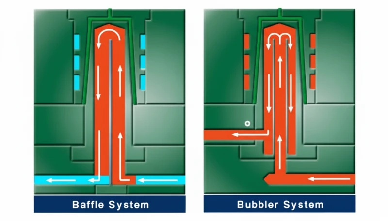
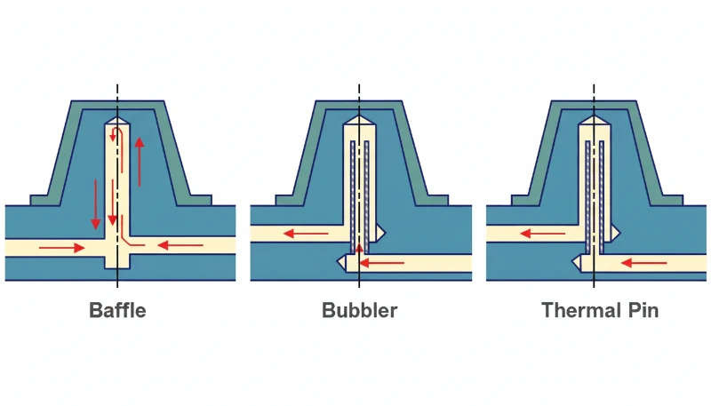
Baffle Cooling Channels
Baffle channels are essentially straight-drill holes with a metal plate (the baffle) inserted down the center, splitting the hole into two halves. Coolant flows up one side and down the other, creating turbulence that improves heat transfer by 30–40% compared to laminar flow in a plain drilled hole. The turbulent flow breaks up the boundary layer that insulates the channel wall.
Baffles are the go-to solution for cooling deep cores and tall ribs where straight-drill channels alone can’t reach. The baffle can be positioned off-center to direct more coolant toward the hottest area of the cavity. They’re relatively inexpensive to add during mold construction but require careful sizing — an undersized baffle restricts flow, while an oversized one reduces cooling surface area.
Spiral Cooling Channels
Spiral channels wrap around cylindrical cores in a helical path, maintaining a consistent distance from the cavity surface throughout the entire circuit. They’re used primarily for round or cylindrical parts — think caps, containers, and pipe fittings — where the geometry naturally suits a helical flow path.
The advantage over straight-drill is uniform cooling distance. In a drilled circuit around a round part, you get dead zones between parallel drill lines. A spiral eliminates those gaps entirely. Coolant enters at the bottom, spirals upward around the core, and exits at the top — or vice versa — ensuring every point on the cylindrical surface receives roughly equal cooling intensity.
Spiral channels are machined by milling a groove into the core surface, then sealing it with a sleeve or inserted ring. This makes them more expensive than straight-drill but still far cheaper than conformal cooling. The main limitation is that spirals only work for rotationally symmetric geometries — they can’t follow irregular contours any better than straight-drill channels can.
Conformal Cooling Channels
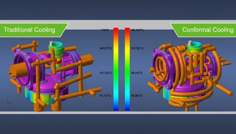
Conformal cooling channels follow the exact contour of the mold cavity, maintaining a uniform distance from the part surface regardless of how complex the geometry is. They’re manufactured using metal 3D printing (selective laser melting) or, in some cases, by machining grooves into split inserts and sealing them with conformal copper alloys.
The result is dramatically more uniform cooling. Areas that would be hot spots in a straight-drill mold — deep pockets, thin ribs, curved surfaces — get the same cooling intensity as flat areas. On a complex medical device housing with 1.2mm walls, conformal cooling can shave 20–35% off cycle time compared to conventional drilling.
The tradeoff is cost. A conformal-cooled insert costs 2–4× more than a drilled equivalent because of the additive manufacturing process. But for high-volume tools running 500K+ shots, the cycle time savings pay for the difference within weeks. We’ve also seen conformal cooling reduce warpage by up to 50% on asymmetrical parts because the temperature gradient across the part is smaller.
Conformal channels can also have variable cross-sections and non-circular profiles, which is impossible with conventional drilling. This allows mold designers to optimize flow velocity and heat transfer coefficient independently in different regions of the same insert — a level of thermal control that straight-drill circuits simply cannot match.
Cooling Mediums: Water, Oil, and Air
Water is the cooling medium in over 90% of injection molding operations worldwide. It offers high thermal conductivity3 (0.6 W/(m·K)), low cost, easy availability, and precise temperature control between 10°C and 90°C using a thermolator or cooling tower. Water also has a high specific heat capacity, meaning it absorbs a large amount of thermal energy per unit volume.
Oil cooling is used when the mold needs to run hotter than 90°C — common with high-performance engineering resins like PEEK (mold temp 160–200°C) or polysulfone (mold temp 120–160°C). Oil systems operate up to 300°C but have roughly 4× lower thermal conductivity than water (0.15 vs 0.6 W/(m·K)) and require more energy to circulate. They also introduce fire risk at high temperatures and add significant maintenance overhead compared to water systems.
Air cooling is rarely used as a primary system because air’s thermal conductivity is roughly 25× lower than water (0.025 vs 0.6 W/(m·K)). You’ll see it as a supplement — compressed air blowing on specific hot spots, or in very low-volume prototype molds where the cost of a water circuit isn’t justified. Some molds use air assist on ejector pins to cool deep cores that water can’t easily reach.
| 속성 | Water | Oil | Air |
|---|---|---|---|
| 열 전도성 | 0.6 W/(m·K) | 0.15 W/(m·K) | 0.025 W/(m·K) |
| Temperature Range | 10–90°C | 50–300°C | Ambient only |
| 비용 | 낮음 | Medium | Very Low |
| Typical Use | Most applications | High-temp resins | Prototype only |
How Cooling Affects Product Quality and Cycle Time
Cooling system performance directly impacts three quality metrics: dimensional accuracy, surface appearance, and mechanical consistency. Uneven cooling — where one area of the part solidifies faster than another — causes internal stresses that lead to warpage, sink marks, and shrinkage variation across the part.
A temperature difference of just 10°C across the part surface can cause measurable dimensional drift of 0.1–0.3mm on a 100mm feature. For tight-tolerance automotive or medical parts where ±0.05mm is the acceptance window, that’s a rejection. And the problem gets worse over a production run — as the mold heats up from continuous cycling, thermal gradients increase, and parts that passed inspection in the first hour start drifting out of spec.
On cycle time: in a typical injection molding cycle, filling takes 1–3 seconds, packing takes 2–5 seconds, and cooling takes 10–40 seconds. Ejection and mold open/close add another 3–8 seconds. Cooling dominates the total cycle, accounting for 70–80% of the elapsed time in most applications.
The math is straightforward. If your current cycle is 20 seconds and you reduce cooling time by 3 seconds (15% improvement), on a 1-million-shot tool you save 833 hours of machine time. At a machine rate of $30–50/hour, that’s $25,000–$41,000 in reduced production cost — more than the price premium for better cooling channels in most cases. This is why optimizing cooling is almost always the highest-ROI improvement you can make to a production mold.
Design Principles for Mold Cooling Systems
Mold cooling design is governed by five core principles. Maximize channel count, keep consistent cavity distance, align coolant flow with material flow, limit inlet-outlet temperature delta to 3–5°C, and ensure turbulent flow in every circuit. More channels at smaller spacing always outperform fewer large channels.
First, maximize channel count and minimize channel spacing. More channels at smaller pitch distances produce a more uniform cavity surface temperature. The practical limit is mold strength — you can’t put channels so close together that the steel between them becomes a weak point. As a rule of thumb, the land width between two parallel channels should be at least equal to the channel diameter.
Five Rules for Effective Cooling Layout
Second, maintain consistent distance from channel to cavity surface — ideally 12–15mm. Closer than 10mm creates cold spots and risks steel cracking under injection pressure; farther than 20mm reduces cooling efficiency significantly.
Third, align coolant flow direction with material flow. The coolant inlet should be near the gate, where the plastic is hottest. This ‘water-material parallel’ approach ensures the coolest water hits the hottest plastic first, then progressively warmer coolant handles the cooler areas of the part. The result is more uniform overall solidification and significantly less warpage.
Fourth, keep the temperature difference between coolant inlet and outlet below 3–5°C. A larger temperature gap means the mold surface near the outlet is significantly warmer than near the inlet — creating the exact kind of uneven cooling that causes warpage and dimensional variation.
Fifth, specify turbulent flow in every circuit — not just adequate flow rate, but actual Reynolds numbers above 4000. Laminar flow (Reynolds < 2300) creates a slow-moving boundary layer along the channel wall that acts as thermal insulation. In practice, this means you need a minimum coolant velocity of 0.5–1.0 m/s through a 10mm channel, which requires a pump capable of delivering 3–5 liters per minute per circuit. Many production molds have channels that appear to be flowing well (you can see water moving) but are actually in the transitional flow regime (Reynolds 2300–4000), leaving 15–20% of potential cooling capacity on the table.
These four principles apply regardless of which channel type you choose. Even a straight-drill mold performs well when the channels are properly spaced, correctly distanced from the cavity, and running turbulent coolant flow. The channel type determines the ceiling of cooling performance — the design principles determine how close you get to that ceiling.
At ZetarMold, our 8 senior engineers review every cooling layout in DFM before steel cutting. On a recent automotive interior program, catching a 20mm channel-to-cavity distance (too far) during DFM saved an estimated 4 seconds per cycle — worth over $120,000 across the tool’s production life.

When to Upgrade from Straight-Drill to Conformal Cooling
Upgrade to conformal cooling when your part has complex geometry — wall variation over 3:1, deep features above 50mm, thin walls under 1.5mm, or annual volume exceeding 200K shots. The decision comes down to part geometry, production volume, and cycle-time cost at your specific machine rate.
Upgrade when: the part has wall thickness variation greater than 3:1, deep features (>50mm) that straight-drill can’t reach, thin walls (<1.5mm) requiring fast and uniform cooling, or annual production volume exceeding 200K shots. In any of these cases, the cycle time savings from conformal cooling will typically pay back the tooling premium within the first production run.
Stay with straight-drill when: the part is simple and flat, wall thickness is uniform, and production volume is under 100K shots. Adding conformal cooling to a simple mold is over-engineering — the cycle time improvement might be only 5–8%, which doesn’t justify the 2–4× cost premium on the insert.
Baffles and spirals fill the middle ground. If you have a moderately complex part but can’t justify conformal cooling cost, baffle channels on deep cores plus spiral channels on cylindrical features will capture 60–70% of the cycle time benefit at 20–30% of the cost premium. This hybrid approach is what we recommend for most mid-volume automotive and consumer electronics programs.
The break-even calculation is simple: (tooling cost premium) ÷ (per-part cycle time savings × machine rate). If the result is less than your expected production volume, conformal cooling pays for itself. If it’s more, stick with conventional channels and invest the savings elsewhere.
“Conformal cooling channels can reduce cycle time by 20–35% on parts with complex geometry.”True
By maintaining uniform distance from the cavity surface, conformal channels eliminate the hot spots that limit ejection timing in conventionally drilled molds. Documented cases show 28% cycle time reduction on 1.2mm wall ABS housings.
“Oil cooling is always better than water cooling because oil can reach higher temperatures.”False
Oil has roughly 4× lower thermal conductivity than water (0.15 vs 0.6 W/(m·K)), meaning slower heat extraction per unit of flow. Oil is only superior when mold temperatures above 90°C are required by the resin — for most applications, water cools faster, cheaper, and safer.
Understanding these facts helps you ask the right questions when evaluating mold quotes from suppliers. Many toolmakers default to straight-drill cooling because it is the lowest-cost option, not because it is the best choice for your part geometry. Asking specifically about cooling channel type, channel-to-cavity distance, and Reynolds number during the DFM stage separates a well-designed tool from one that will cost you money in scrap and lost productivity over its entire production life. If your supplier cannot explain their cooling strategy in terms of these fundamentals, that is a red flag worth investigating before committing to tooling.
“The coolant inlet should be positioned near the gate area for optimal cooling uniformity.”True
Placing the coolest water near the gate — where the plastic is hottest — aligns coolant flow with material flow. This ‘water-material parallel’ approach reduces the temperature gradient across the part by 40–60%, preventing warpage from differential cooling and allowing earlier part ejection.
“직선 드릴 냉각 채널은 모든 부품 형상에 동등하게 잘 작동합니다.”False
직선 드릴 채널은 곡선형이거나 깊은 캐비티 특징을 따라갈 수 없어, 높은 리브, 깊은 포켓, 곡면과 같은 영역에 핫스팟을 남깁니다. 벽 두께 변화가 3:1을 초과하거나 50mm 이상의 깊은 특징이 있는 부품의 경우, 허용 가능한 냉각 균일성을 달성하기 위해 배플 또는 컨포멀 채널이 필요합니다.
자주 묻는 질문
자주 묻는 질문
사출 금형에서 가장 일반적으로 사용되는 냉각 시스템은 무엇인가요?
직선 드릴 냉각 채널은 전 세계 생산 금형의 80% 이상에서 사용되는 가장 일반적인 시스템입니다. 이는 가장 저렴한 옵션이며, 금형 전체에 걸쳐 균일한 채널-캐비티 거리를 유지할 수 있는 비교적 단순하고 평평한 형상의 부품에 잘 작동합니다. 더 복잡한 부품의 경우, 공구 제작자는 일반적으로 직선 드릴 회로를 중요한 영역에서 배플 또는 컨포멀 인서트로 보완합니다. 10~80°C의 물은 표준 냉각제이며, 목표 금형 온도를 ±1°C 이내로 유지하는 온도 제어 장치(TCU)에 의해 순환됩니다.
컨포멀 냉각은 금형 비용에 얼마나 추가되나요?
컨포멀 냉각은 채널 제조에 필요한 금속 3D 프린팅(SLM) 공정으로 인해 기존 드릴 가공 대비 냉각 인서트 비용을 일반적으로 2–4배 증가시킵니다. 기존 드릴 가공으로 $3,000–$5,000원이 드는 표준 생산 인서트의 경우, 컨포멀 버전은 $8,000–$15,000원 정도 될 수 있습니다. 그러나 50만 샷 이상을 생산하는 대량 생산 금형의 경우, 20–35%의 사이클 타임 단축으로 인해 이 추가 비용은 보통 처음 몇 번의 생산 런 내에 회수됩니다. 정확한 회수 기간은 기계 시간당 비율과 성형되는 부품의 특정 형상에 따라 달라집니다.
냉각수 온도는 얼마로 해야 하나요?
냉각수 온도는 성형되는 재료에 따라 달라지며, 수지 제조업체에서 지정합니다. 일반적인 범위는 PP 및 PE(빠른 결정화)와 같은 범용 수지의 경우 10~30°C, ABS 및 PC와 같은 비정질 수지의 경우 40~60°C, 적절한 결정화를 위해 더 따뜻한 금형이 필요한 PA66 및 PBT와 같은 엔지니어링 수지의 경우 60~80°C입니다. 열가소성 수지 제조업체의 데이터시트에는 항상 권장 금형 온도 범위가 나열되어 있습니다. 너무 낮은 온도로 운전하면 흐름 흔적과 높은 잔류 응력이 발생할 수 있으며, 너무 높은 온도로 운전하면 불필요하게 사이클 시간이 길어집니다.
금형 냉각에 물이 공기보다 더 나은 이유는 무엇인가요?
물의 열전도율은 공기보다 약 25배 높습니다(0.6 vs 0.025 W/(m·K)), 이는 단위 유량당 금형에서 열을 훨씬 더 효율적으로 제거한다는 의미입니다. 물은 또한 훨씬 높은 비열 용량을 가지고 있어 온도가 크게 상승하기 전에 더 많은 열 에너지를 흡수할 수 있습니다. 또한, 물은 열온도 조절기(±1°C 정확도)를 통해 정밀한 온도 제어가 가능한 반면, 공기 냉각은 거의 온도 조절 능력을 제공하지 않습니다. 공기는 매우 특정한 시나리오 — 프로토타입 금형, 국부적 핫스팟 냉각, 또는 물 누출 위험이 허용되지 않는 경우 — 에서만 보조적으로 사용됩니다.
불량한 냉각이 사출 성형 부품의 뒤틀림을 어떻게 유발하나요?
불균일한 냉각은 부품 전체에 온도 구배를 생성합니다. 한 영역은 고화되고 수축하는 동안 다른 영역은 여전히 뜨겁고 다른 속도로 수축합니다. 이 차등 수축은 부품이 이젝트되고 실온으로 냉각된 후 의도된 형상에서 벗어나도록 하는 내부 응력을 발생시킵니다. 캐비티 표면의 단지 10°C 온도 변화만으로도 100mm 피처에 0.1–0.3mm의 치수 변동을 유발할 수 있습니다. 이 효과는 벽 두께가 균일하지 않거나, 길고 얇은 단면, 또는 비대칭 형상을 가진 부품에서 가장 두드러지게 나타납니다. 이러한 부품들은 이를 보상하기 위해 가장 신중한 냉각 채널 설계가 필요한 부품들입니다.
냉각 채널과 캐비티 표면 사이의 이상적인 거리는 얼마인가요?
냉각 채널 벽에서 캐비티 표면까지의 권장 거리는 12~15mm 또는 표준 8~10mm 드릴 크기의 경우 채널 직경의 약 1.5~2.0배입니다. 이 범위는 열 추출 효율과 금형 구조적 안정성 사이의 균형을 맞춥니다. 10mm보다 가까우면 부품 표면에 국부적 콜드 스팟이 생성되고 높은 사출 압력(일반적으로 80~140 MPa) 하에서 강철 균열 위험이 있습니다. 20mm보다 멀면 냉각 효율이 크게 감소합니다 — 강철이 단열재 역할을 하게 되어, 더 많은 냉각제를 순환시키게 되지만 캐비티에서 실제 열 제거에 대한 효과는 점차 줄어듭니다.
한 금형에서 다른 유형의 냉각 채널을 결합할 수 있나요?
네, 채널 유형을 결합하는 것은 생산 금형에서 표준 관행이며 종종 가장 비용 효율적인 접근 방식입니다. 일반적인 구성은 부품의 평평한 영역에는 직선 드릴 회로를, 깊은 코어와 높은 리브에는 배플 채널을, 원통형 특징 주변에는 나선형 채널을, 그리고 가장 복잡하거나 열적으로 중요한 영역에만 컨포멀 인서트를 사용합니다. 이 하이브리드 전략은 전체 공구를 과도하게 설계하지 않으면서 비용과 성능을 균형시킵니다. ZetarMold에서는 생산 금형의 약 60%에 이 혼합 방식을 지정합니다 — 이는 전체 컨포멀 냉각의 열 성능의 70~80%를 비용 프리미엄의 30~40%로 달성합니다.


