 Ir al contenido

- Los cuatro tipos principales de canales de enfriamiento para moldes de inyección son: taladro recto, deflector, espiral y conformado.
- El enfriamiento representa el 70–80% del tiempo total del ciclo — la palanca más grande para la productividad.
- El enfriamiento conformal reduce el tiempo de ciclo en un 20–35% en comparación con los canales perforados rectos en geometrías complejas.
- El agua es el refrigerante más común; el aceite se usa para moldes que requieren temperaturas superiores a 90°C.
- El enfriamiento uniforme evita la deformación, las marcas de hundimiento y la variación dimensional en las piezas terminadas.
Por qué la elección del sistema de enfriamiento hace o deshace su molde
Elegir el sistema de enfriamiento adecuado es la decisión más impactante en el diseño de moldes — controla el 70–80% de su duración del ciclo1. Al evaluar un proveedor de moldeo por inyección para un molde de producción, comprender las opciones de enfriamiento es esencial. Si se equivoca, lo pagará en desperdicio y pérdida de productividad durante toda la vida útil de la herramienta. Este artículo desglosa los cuatro tipos principales de canales de enfriamiento y le da los criterios para elegir el correcto.
El enfriamiento no es una consideración secundaria en el moldeo por inyección. Controla el 70–80% de su proceso de moldeo por inyección tiempo. La diferencia entre un molde bien enfriado y uno mal enfriado puede significar un ciclo de 12 segundos frente a uno de 18 segundos — en una herramienta de un millón de disparos, esa es la diferencia entre rentable y no.
Este artículo desglosa los cuatro tipos principales de sistemas de enfriamiento utilizados en moldes de inyección, compara su rendimiento y le brinda los criterios para elegir el adecuado para su aplicación. Ya sea que esté especificando su primera herramienta de producción u optimizando una existente, comprender los tipos de canales de enfriamiento es el camino más rápido hacia mejores piezas y menores costos unitarios.
La elección incorrecta de enfriamiento no solo lo ralentiza — crea problemas de calidad que se agravan con el tiempo. El enfriamiento desigual causa deformación, marcas de hundimiento y desviación dimensional que empeoran a medida que el molde se calienta durante una corrida de producción. Corregir estos problemas posteriormente (clasificación, retrabajo, desecho) cuesta 5–10 veces más que hacer bien el enfriamiento en la etapa de diseño.
¿Qué es un Sistema de Enfriamiento de Molde de Inyección?
Un sistema de enfriamiento de molde de inyección extrae calor del plástico fundido a través de canales internos — y controla el 70–80% de su tiempo de ciclo. El sistema de enfriamiento es el mayor contribuyente al tiempo de ciclo en el moldeo por inyección.
Cuando el plástico fundido caliente (típicamente 200–300°C) entra en la cavidad, transfiere calor a las paredes de acero del molde. Sin enfriamiento activo, una pieza de ABS de 3 mm de espesor tardaría más de 120 segundos en solidificarse lo suficiente para la expulsión. Con un circuito de agua diseñado adecuadamente, esa misma pieza se expulsa en 15–25 segundos — una mejora de 5–8 veces.
El sistema de enfriamiento afecta tres resultados críticos: tiempo de ciclo (productividad), calidad de la pieza (estabilidad dimensional y apariencia) y longevidad del molde (fatiga térmica). Hacerlo bien desde el molde de inyección etapa de diseño es mucho más barato que rediseñar los canales después de cortar el acero. Un rediseño del enfriamiento después de T0 típicamente cuesta $5,000–$15,000 y añade 2–4 semanas al cronograma.
El circuito de enfriamiento consta de varios elementos que trabajan juntos: los canales internos perforados o formados en el acero del molde, la plomería externa (mangueras, colectores, conexiones rápidas), la unidad de control de temperatura (TCU o termorregulador) que calienta o enfría el refrigerante, y el sistema de gestión del flujo que asegura un flujo turbulento para una transferencia de calor máxima.
En ZetarMold, cambiar de perforación recta a conformal cooling2 canales reduce el tiempo de ciclo en un 20–35% en piezas de pared delgada. Documentamos una reducción del tiempo de ciclo del 28% en un programa de carcasa de ABS de pared de 1.2 mm en 2024.
Tipos de Canales de Enfriamiento en Moldes de Inyección
Los cuatro tipos principales de canales de enfriamiento son perforación recta, deflector, espiral y conformado — cada uno adecuado para diferentes geometrías y volúmenes. La siguiente tabla resume cómo se comparan en impacto en el tiempo de ciclo, costo de herramienta y complejidad.
| Tipo de Canal | Caso típico | Cycle Time Impact | Coste de utillaje | Complejidad |
|---|---|---|---|---|
| Perforación recta | Piezas planas y simples | Baseline | Bajo | Bajo |
| Deflector | Núcleos profundos, nervaduras altas | 10–15% más rápido que la perforación | Medio | Medio |
| Espiral | Piezas cilíndricas, redondas | 15–20% más rápido que el taladro | Medio | Medio |
| Conformal | Geometrías complejas, paredes delgadas | 20–35% más rápido que la perforación | Alta | Alta |
Canales de Enfriamiento Rectos Perforados
Los canales de taladro recto son el método de enfriamiento más común y menos costoso. El fabricante del molde perfora una serie de agujeros rectos de sección transversal circular a través de las placas del molde, luego los conecta con tapones y mangueras para formar un circuito. Más del 80% de todos los moldes de producción utilizan el enfriamiento por taladro recto como método principal.
Estos canales funcionan bien para piezas planas y de espesor uniforme — piense en bandejas simples, tapas planas o carcasas rectangulares. La limitación es la geometría: solo se pueden perforar líneas rectas, por lo que la distancia del canal a la superficie de la cavidad varía. En áreas donde la cavidad se curva o tiene características profundas, la trayectoria de perforación no puede seguir, dejando puntos calientes que extienden el tiempo de enfriamiento.
Los diámetros de perforación típicos oscilan entre 6 mm y 12 mm. La distancia desde la pared del canal a la superficie de la cavidad debe ser 1.5–2.0 veces el diámetro del canal — generalmente 12–15 mm — para equilibrar la eficiencia de enfriamiento con la integridad estructural del acero del molde. Un espaciado más cercano mejora la uniformidad de la temperatura pero debilita el acero entre los canales.
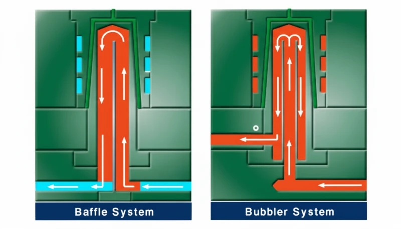
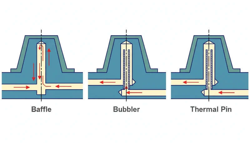
Canales de Enfriamiento con Deflector
Los canales con deflector son esencialmente agujeros perforados rectos con una placa metálica (el deflector) insertada en el centro, dividiendo el agujero en dos mitades. El refrigerante fluye hacia arriba por un lado y hacia abajo por el otro, creando turbulencia que mejora la transferencia de calor en un 30–40% en comparación con el flujo laminar en un agujero perforado simple. El flujo turbulento rompe la capa límite que aísla la pared del canal.
Las deflectores son la solución preferida para enfriar núcleos profundos y nervaduras altas donde los canales perforados rectos por sí solos no pueden llegar. El deflector puede colocarse descentrado para dirigir más refrigerante hacia la zona más caliente de la cavidad. Son relativamente económicos de añadir durante la construcción del molde, pero requieren un dimensionado cuidadoso — un deflector demasiado pequeño restringe el flujo, mientras que uno demasiado grande reduce el área de superficie de enfriamiento.
Canales de Enfriamiento en Espiral
Spiral channels wrap around cylindrical cores in a helical path, maintaining a consistent distance from the cavity surface throughout the entire circuit. They’re used primarily for round or cylindrical parts — think caps, containers, and pipe fittings — where the geometry naturally suits a helical flow path.
The advantage over straight-drill is uniform cooling distance. In a drilled circuit around a round part, you get dead zones between parallel drill lines. A spiral eliminates those gaps entirely. Coolant enters at the bottom, spirals upward around the core, and exits at the top — or vice versa — ensuring every point on the cylindrical surface receives roughly equal cooling intensity.
Spiral channels are machined by milling a groove into the core surface, then sealing it with a sleeve or inserted ring. This makes them more expensive than straight-drill but still far cheaper than conformal cooling. The main limitation is that spirals only work for rotationally symmetric geometries — they can’t follow irregular contours any better than straight-drill channels can.
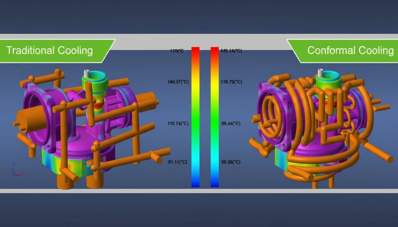
Conformal Cooling Channels
Conformal cooling channels follow the exact contour of the mold cavity, maintaining a uniform distance from the part surface regardless of how complex the geometry is. They’re manufactured using metal 3D printing (selective laser melting) or, in some cases, by machining grooves into split inserts and sealing them with conformal copper alloys.
The result is dramatically more uniform cooling. Areas that would be hot spots in a straight-drill mold — deep pockets, thin ribs, curved surfaces — get the same cooling intensity as flat areas. On a complex medical device housing with 1.2mm walls, conformal cooling can shave 20–35% off cycle time compared to conventional drilling.
The tradeoff is cost. A conformal-cooled insert costs 2–4× more than a drilled equivalent because of the additive manufacturing process. But for high-volume tools running 500K+ shots, the cycle time savings pay for the difference within weeks. We’ve also seen conformal cooling reduce warpage by up to 50% on asymmetrical parts because the temperature gradient across the part is smaller.
Conformal channels can also have variable cross-sections and non-circular profiles, which is impossible with conventional drilling. This allows mold designers to optimize flow velocity and heat transfer coefficient independently in different regions of the same insert — a level of thermal control that straight-drill circuits simply cannot match.
Medios de Enfriamiento: Agua, Aceite y Aire
Water is the cooling medium in over 90% of injection molding operations worldwide. It offers high conductividad térmica3 (0.6 W/(m·K)), low cost, easy availability, and precise temperature control between 10°C and 90°C using a thermolator or cooling tower. Water also has a high specific heat capacity, meaning it absorbs a large amount of thermal energy per unit volume.
Oil cooling is used when the mold needs to run hotter than 90°C — common with high-performance engineering resins like PEEK (mold temp 160–200°C) or polysulfone (mold temp 120–160°C). Oil systems operate up to 300°C but have roughly 4× lower thermal conductivity than water (0.15 vs 0.6 W/(m·K)) and require more energy to circulate. They also introduce fire risk at high temperatures and add significant maintenance overhead compared to water systems.
Air cooling is rarely used as a primary system because air’s thermal conductivity is roughly 25× lower than water (0.025 vs 0.6 W/(m·K)). You’ll see it as a supplement — compressed air blowing on specific hot spots, or in very low-volume prototype molds where the cost of a water circuit isn’t justified. Some molds use air assist on ejector pins to cool deep cores that water can’t easily reach.
| Propiedad | Agua | Aceite | Aire |
|---|---|---|---|
| Conductividad térmica | 0.6 W/(m·K) | 0.15 W/(m·K) | 0.025 W/(m·K) |
| Temperature Range | 10–90°C | 50–300°C | Ambient only |
| Coste | Bajo | Medio | Very Low |
| Typical Use | Most applications | High-temp resins | Prototype only |
Cómo el Enfriamiento Afecta la Calidad del Producto y el Tiempo de Ciclo
Cooling system performance directly impacts three quality metrics: dimensional accuracy, surface appearance, and mechanical consistency. Uneven cooling — where one area of the part solidifies faster than another — causes internal stresses that lead to warpage, sink marks, and shrinkage variation across the part.
A temperature difference of just 10°C across the part surface can cause measurable dimensional drift of 0.1–0.3mm on a 100mm feature. For tight-tolerance automotive or medical parts where ±0.05mm is the acceptance window, that’s a rejection. And the problem gets worse over a production run — as the mold heats up from continuous cycling, thermal gradients increase, and parts that passed inspection in the first hour start drifting out of spec.
On cycle time: in a typical injection molding cycle, filling takes 1–3 seconds, packing takes 2–5 seconds, and cooling takes 10–40 seconds. Ejection and mold open/close add another 3–8 seconds. Cooling dominates the total cycle, accounting for 70–80% of the elapsed time in most applications.
The math is straightforward. If your current cycle is 20 seconds and you reduce cooling time by 3 seconds (15% improvement), on a 1-million-shot tool you save 833 hours of machine time. At a machine rate of $30–50/hour, that’s $25,000–$41,000 in reduced production cost — more than the price premium for better cooling channels in most cases. This is why optimizing cooling is almost always the highest-ROI improvement you can make to a production mold.
Principios de Diseño para Sistemas de Enfriamiento de Moldes
Mold cooling design is governed by five core principles. Maximize channel count, keep consistent cavity distance, align coolant flow with material flow, limit inlet-outlet temperature delta to 3–5°C, and ensure turbulent flow in every circuit. More channels at smaller spacing always outperform fewer large channels.
First, maximize channel count and minimize channel spacing. More channels at smaller pitch distances produce a more uniform cavity surface temperature. The practical limit is mold strength — you can’t put channels so close together that the steel between them becomes a weak point. As a rule of thumb, the land width between two parallel channels should be at least equal to the channel diameter.
Five Rules for Effective Cooling Layout
Second, maintain consistent distance from channel to cavity surface — ideally 12–15mm. Closer than 10mm creates cold spots and risks steel cracking under injection pressure; farther than 20mm reduces cooling efficiency significantly.
Third, align coolant flow direction with material flow. The coolant inlet should be near the gate, where the plastic is hottest. This ‘water-material parallel’ approach ensures the coolest water hits the hottest plastic first, then progressively warmer coolant handles the cooler areas of the part. The result is more uniform overall solidification and significantly less warpage.
Fourth, keep the temperature difference between coolant inlet and outlet below 3–5°C. A larger temperature gap means the mold surface near the outlet is significantly warmer than near the inlet — creating the exact kind of uneven cooling that causes warpage and dimensional variation.
Fifth, specify turbulent flow in every circuit — not just adequate flow rate, but actual Reynolds numbers above 4000. Laminar flow (Reynolds < 2300) creates a slow-moving boundary layer along the channel wall that acts as thermal insulation. In practice, this means you need a minimum coolant velocity of 0.5–1.0 m/s through a 10mm channel, which requires a pump capable of delivering 3–5 liters per minute per circuit. Many production molds have channels that appear to be flowing well (you can see water moving) but are actually in the transitional flow regime (Reynolds 2300–4000), leaving 15–20% of potential cooling capacity on the table.
These four principles apply regardless of which channel type you choose. Even a straight-drill mold performs well when the channels are properly spaced, correctly distanced from the cavity, and running turbulent coolant flow. The channel type determines the ceiling of cooling performance — the design principles determine how close you get to that ceiling.
At ZetarMold, our 8 senior engineers review every cooling layout in DFM before steel cutting. On a recent automotive interior program, catching a 20mm channel-to-cavity distance (too far) during DFM saved an estimated 4 seconds per cycle — worth over $120,000 across the tool’s production life.

Cuándo actualizar de enfriamiento por perforación recta a enfriamiento conformal
Upgrade to conformal cooling when your part has complex geometry — wall variation over 3:1, deep features above 50mm, thin walls under 1.5mm, or annual volume exceeding 200K shots. The decision comes down to part geometry, production volume, and cycle-time cost at your specific machine rate.
Upgrade when: the part has wall thickness variation greater than 3:1, deep features (>50mm) that straight-drill can’t reach, thin walls (<1.5mm) requiring fast and uniform cooling, or annual production volume exceeding 200K shots. In any of these cases, the cycle time savings from conformal cooling will typically pay back the tooling premium within the first production run.
Stay with straight-drill when: the part is simple and flat, wall thickness is uniform, and production volume is under 100K shots. Adding conformal cooling to a simple mold is over-engineering — the cycle time improvement might be only 5–8%, which doesn’t justify the 2–4× cost premium on the insert.
Baffles and spirals fill the middle ground. If you have a moderately complex part but can’t justify conformal cooling cost, baffle channels on deep cores plus spiral channels on cylindrical features will capture 60–70% of the cycle time benefit at 20–30% of the cost premium. This hybrid approach is what we recommend for most mid-volume automotive and consumer electronics programs.
The break-even calculation is simple: (tooling cost premium) ÷ (per-part cycle time savings × machine rate). If the result is less than your expected production volume, conformal cooling pays for itself. If it’s more, stick with conventional channels and invest the savings elsewhere.
“Conformal cooling channels can reduce cycle time by 20–35% on parts with complex geometry.”Verdadero
By maintaining uniform distance from the cavity surface, conformal channels eliminate the hot spots that limit ejection timing in conventionally drilled molds. Documented cases show 28% cycle time reduction on 1.2mm wall ABS housings.
“Oil cooling is always better than water cooling because oil can reach higher temperatures.”Falso
El aceite tiene una conductividad térmica aproximadamente 4 veces menor que el agua (0,15 frente a 0,6 W/(m·K)), lo que significa una extracción de calor más lenta por unidad de flujo. El aceite solo es superior cuando la resina requiere temperaturas del molde superiores a 90°C —para la mayoría de las aplicaciones, el agua enfría más rápido, más barato y de manera más segura.
Comprender estos hechos le ayuda a hacer las preguntas correctas al evaluar cotizaciones de moldes de proveedores. Muchos fabricantes de moldes optan por defecto por el enfriamiento recto porque es la opción de menor costo, no porque sea la mejor elección para la geometría de su pieza. Preguntar específicamente sobre el tipo de canal de enfriamiento, la distancia entre el canal y la cavidad, y el número de Reynolds durante la etapa de DFM diferencia un molde bien diseñado de uno que le costará dinero en desperdicio y pérdida de productividad a lo largo de toda su vida productiva. Si su proveedor no puede explicar su estrategia de enfriamiento en términos de estos fundamentos, es una señal de alerta que vale la pena investigar antes de comprometerse con la fabricación del molde.
“The coolant inlet should be positioned near the gate area for optimal cooling uniformity.”Verdadero
Placing the coolest water near the gate — where the plastic is hottest — aligns coolant flow with material flow. This ‘water-material parallel’ approach reduces the temperature gradient across the part by 40–60%, preventing warpage from differential cooling and allowing earlier part ejection.
“Straight-drill cooling channels work equally well for all part geometries.”Falso
Los canales de perforación recta no pueden seguir características de cavidad curvadas o profundas, dejando puntos calientes en áreas como nervaduras altas, cavidades profundas y superficies curvadas. Para piezas con variación de grosor de pared superior a 3:1 o características profundas sobre 50mm, canales deflectores o conformales son necesarios para lograr una uniformidad de refrigeración aceptable.
Preguntas frecuentes
Preguntas frecuentes
¿Cuál es el sistema de refrigeración más común utilizado en moldes de inyección?
Los canales de refrigeración por agua de perforación recta son el sistema más común, utilizado en más del 80% de los moldes de producción mundial. Son la opción de menor costo y funcionan bien para piezas con geometrías relativamente simples y planas donde se puede mantener una distancia uniforme entre el canal y la cavidad en todo el molde. Para piezas más complejas, los fabricantes de herramientas generalmente complementan los circuitos de perforación recta con deflectores o insertos conformales en áreas críticas. El agua a 10–80°C es el refrigerante estándar, circulada por una unidad de control de temperatura (TCU) que mantiene la temperatura objetivo del molde dentro de ±1°C.
¿Cuánto añade el enfriamiento conformacional al costo del molde?
La refrigeración conformal generalmente añade 2–4 veces el costo al inserto refrigerado en comparación con la perforación convencional, debido al proceso de impresión 3D de metal (fusión por láser selectiva) requerido para fabricar los canales. Para un inserto de producción estándar que cuesta $3,000–$5,000 con perforación convencional, la versión conformal podría costar $8,000–$15,000. Sin embargo, para herramientas de alto volumen que ejecutan 500K+ ciclos, la reducción del tiempo de ciclo de 20–35% generalmente recupera este costo adicional dentro de los primeros ciclos de producción. El período exacto de recuperación depende de su tarifa horaria de máquina y la geometría específica de la pieza que se está moldeando.
¿Qué temperatura debe tener el agua de refrigeración?
La temperatura del agua de refrigeración depende del material que se está moldeando y está especificada por el fabricante de la resina. Rangos comunes incluyen 10–30°C para resinas commodity como PP y PE (cristalización rápida), 40–60°C para resinas amorfas como ABS y PC, y 60–80°C para resinas de ingeniería como PA66 y PBT que requieren moldes más cálidos para una cristalización adecuada. La hoja de datos del fabricante del termoplástico siempre lista el rango de temperatura recomendado del molde. Operar demasiado frío puede causar marcas de flujo y alto estrés residual; operar demasiado caliente extiende innecesariamente el tiempo de ciclo.
¿Por qué el agua es mejor que el aire para la refrigeración del molde?
El agua tiene aproximadamente 25 veces más conductividad térmica que el aire (0.6 vs 0.025 W/(m·K)), lo que significa que extrae calor del molde mucho más eficientemente por unidad de flujo. El agua también tiene una capacidad calorífica específica mucho mayor, permitiendo absorber más energía térmica antes que su temperatura aumente significativamente. Además, el agua permite un control preciso de temperatura mediante termorreguladores (±1°C de precisión), mientras que la refrigeración por aire ofrece casi ninguna capacidad de regulación de temperatura. El aire solo se usa como complemento en escenarios muy específicos — moldes prototipo, refrigeración localizada de puntos calientes, o donde el riesgo de fugas de agua es inadmisible.
¿Cómo causa la refrigeración deficiente deformaciones en piezas moldeadas por inyección?
El enfriamiento desigual crea gradientes de temperatura a lo largo de la pieza: una región se solidifica y encoge mientras otra aún está caliente y se contrae a un ritmo diferente. Esta contracción diferencial genera tensiones internas que deforman la pieza de su forma prevista una vez que es expulsada y se enfría a temperatura ambiente. Una variación de temperatura de solo 10°C en la superficie de la cavidad puede causar una desviación dimensional de 0,1 a 0,3 mm en una característica de 100 mm. El efecto es más pronunciado en piezas con espesor de pared no uniforme, secciones largas y delgadas o geometría asimétrica, precisamente las piezas que requieren el diseño de canales de enfriamiento más cuidadoso para compensar.
¿Cuál es la distancia ideal entre los canales de refrigeración y la superficie de la cavidad?
La distancia recomendada desde la pared del canal de refrigeración a la superficie de la cavidad es de 12–15mm, o aproximadamente 1.5–2.0× el diámetro del canal para tamaños de perforación estándar de 8–10mm. Este rango equilibra la eficiencia de extracción de calor contra la integridad estructural del molde. Más cerca de 10mm crea puntos fríos localizados en la superficie de la pieza y riesgo de fractura del acero bajo las altas presiones de inyección (típicamente 80–140 MPa). Más allá de 20mm reduce significativamente la eficiencia de refrigeración — el acero actúa como aislamiento térmico, y termina circulando más refrigerante con rendimientos decrecientes en la remoción real de calor de la cavidad.
¿Se pueden combinar diferentes tipos de canal de refrigeración en un molde?
Sí, combinar tipos de canal es una práctica estándar en moldes de producción y es frecuentemente la aproximación más rentable. Una configuración común utiliza circuitos de perforación recta para áreas planas de la pieza, canales deflectores en núcleos profundos y nervaduras altas, canales espiral alrededor de características cilíndricas, y insertos conformales solo en las regiones más complejas o críticas térmicamente. Esta estrategia híbrida equilibra costo y rendimiento sin sobreingenierizar toda la herramienta. En ZetarMold, especificamos esta aproximación mixta en aproximadamente 60% de los moldes de producción — captura 70–80% del rendimiento térmico de la refrigeración conformal completa con un costo adicional de 30–40%.
-
duración del ciclo: El tiempo de ciclo es la duración total de un ciclo completo de moldeo por inyección, medida en segundos, desde el cierre del molde hasta la expulsión de la pieza. ↩
-
conformal cooling: El enfriamiento conformacional se refiere a canales de enfriamiento que siguen el contorno de la superficie de la cavidad del molde, típicamente fabricados mediante impresión 3D en metal o fabricación aditiva. ↩
-
conductividad térmica: La conductividad térmica es una propiedad del material medida en W/(m·K) que cuantifica la velocidad a la que el calor se transfiere a través de una sustancia. ↩


