 Vai al contenuto

- I quattro principali tipi di canali di raffreddamento per stampi a iniezione sono a foratura diritta, a deflettore, a spirale e conformi.
- Il raffreddamento rappresenta il 70–80% del tempo di ciclo totale — la leva più importante per la produttività.
- Il raffreddamento conforme riduce il tempo di ciclo del 20–35% rispetto ai canali a punta diritta su geometrie complesse.
- L'acqua è il refrigerante più comune; l'olio viene utilizzato per stampi che richiedono temperature superiori a 90°C.
- Un raffreddamento uniforme previene deformazioni, segni di ritiro e variazioni dimensionali nei pezzi finiti.
Perché la scelta del sistema di raffreddamento fa la differenza per il tuo stampo
Scegliere il sistema di raffreddamento giusto è la decisione più influente nella progettazione dello stampo — controlla il 70–80% del vostro tempo di ciclo1. Quando si valuta un fornitore di stampaggio a iniezione per uno stampo di produzione, comprendere le opzioni di raffreddamento è essenziale. Se sbagli, ne paghi le conseguenze in scarti e produttività persa per l'intera vita dello strumento. Questo articolo suddivide i quattro principali tipi di canali di raffreddamento e ti fornisce i criteri per scegliere quello giusto.
Il raffreddamento non è una considerazione secondaria nello stampaggio a iniezione. Controlla il 70–80% del vostro totale processo di stampaggio a iniezione time. The difference between a well-cooled mold and a poorly cooled one can mean a 12-second cycle versus an 18-second cycle — on a million-shot tool, that’s the difference between profitable and not.
This article breaks down the four main types of cooling systems used in injection molds, compares their performance, and gives you the criteria to choose the right one for your application. Whether you’re specifying your first production tool or optimizing an existing one, understanding cooling channel types is the fastest path to better parts and lower unit costs.
The wrong cooling choice doesn’t just slow you down — it creates quality problems that compound over time. Uneven cooling causes warpage, sink marks, and dimensional drift that get worse as the mold heats up during a production run. Fixing these issues downstream (sorting, rework, scrap) costs 5–10× more than getting the cooling right at the design stage.
What Is an Injection Mold Cooling System?
Un sistema di raffreddamento per stampi a iniezione estrae calore dalla plastica fusa tramite canali interni — e controlla il 70–80% del vostro tempo di ciclo. Il sistema di raffreddamento è il singolo fattore che contribuisce maggiormente al tempo di ciclo nello stampaggio a iniezione.
Quando la plastica fusa calda (tipicamente 200–300°C) entra nella cavità, trasferisce calore alle pareti dello stampo in acciaio. Senza un raffreddamento attivo, una parte in ABS di 3 mm di spessore impiegherebbe oltre 120 secondi per solidificarsi abbastanza per l'espulsione. Con un circuito ad acqua progettato correttamente, quella stessa parte viene espulsa in 15–25 secondi — un miglioramento di 5–8×.
Il sistema di raffreddamento influisce su tre risultati critici: tempo di ciclo (produttività), qualità del pezzo (stabilità dimensionale e aspetto) e longevità dello stampo (fatica termica). Farlo correttamente al stampo a iniezione La fase di progettazione è molto più economica che riprogettare i canali dopo che l'acciaio è stato tagliato. Una riprogettazione del raffreddamento dopo T0 costa tipicamente $5.000–$15.000 e aggiunge 2–4 settimane al programma.
Il circuito di raffreddamento è composto da diversi elementi che lavorano insieme: i canali interni perforati o formati nell'acciaio dello stampo, la tubazione esterna (tubi, collettori, raccordi a innesto rapido), l'unità di controllo della temperatura (TCU o termoregolatore) che riscalda o raffredda il refrigerante, e il sistema di gestione del flusso che garantisce un flusso turbolento per il massimo trasferimento di calore.
Presso ZetarMold, passare dalla punta diritta a conformal cooling2 i canali riducono il tempo di ciclo del 20–35% su parti a parete sottile. Nel 2024 abbiamo documentato una riduzione del tempo di ciclo del 28% su un programma di alloggiamento ABS con parete di 1,2 mm.
Tipi di canali di raffreddamento negli stampi a iniezione
I quattro principali tipi di canali di raffreddamento sono a foratura diritta, a deflettore, a spirale e conformi — ciascuno adatto a geometrie e volumi diversi. La tabella seguente riassume come si confrontano in termini di impatto sul tempo di ciclo, costo dell'utensilatura e complessità.
| Tipo di Canale | Caso d'uso tipico | Cycle Time Impact | Costo degli utensili | Complessità |
|---|---|---|---|---|
| Foratura diritta | Parti semplici e piatte | Baseline | Basso | Basso |
| Deflettore | Nuclei profondi, nervature alte | 10–15% più veloce della punta | Medio | Medio |
| Spirale | Parti cilindriche, rotonde | 15–20% più veloce della foratura | Medio | Medio |
| Conforme | Geometrie complesse, pareti sottili | 20–35% più veloce della foratura | Alto | Alto |
Canali di Raffreddamento a Foratura Diritta
I canali a foratura diritta sono il metodo di raffreddamento più comune e meno costoso. Il costruttore dello stampo pratica una serie di fori diritti a sezione circolare attraverso le piastre dello stampo, quindi li collega con tappi e tubi per formare un circuito. Oltre l'80% di tutti gli stampi di produzione utilizza il raffreddamento a foratura diritta come metodo principale.
These channels work well for flat, uniform-thickness parts — think simple trays, flat covers, or rectangular housings. The limitation is geometry: you can only drill straight lines, so the channel distance from the cavity surface varies. In areas where the cavity curves or has deep features, the drill path can’t follow, leaving hot spots that extend cooling time.
I diametri tipici dei fori vanno da 6 mm a 12 mm. La distanza dalla parete del canale alla superficie della cavità dovrebbe essere 1,5–2,0 volte il diametro del canale — generalmente 12–15 mm — per bilanciare l'efficienza di raffreddamento con l'integrità strutturale dell'acciaio dello stampo. Una spaziatura più ravvicinata migliora l'uniformità della temperatura ma indebolisce l'acciaio tra i canali.
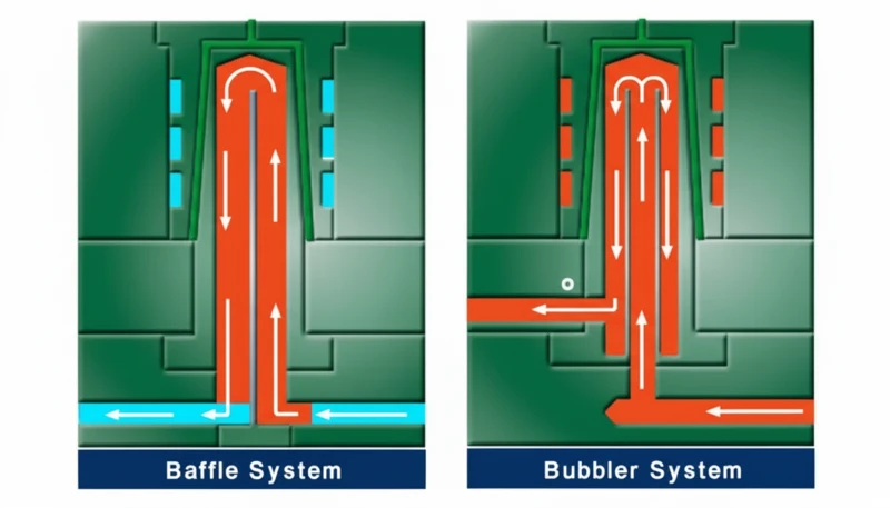
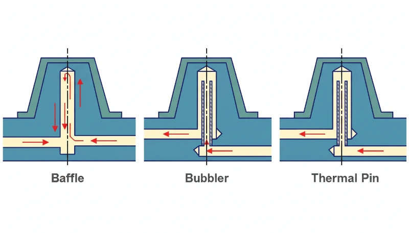
Canali di raffreddamento a deflettore
I canali a deflettore sono essenzialmente fori a foratura diritta con una piastra metallica (il deflettore) inserita al centro, che divide il foro in due metà. Il refrigerante scorre su un lato e giù dall'altro, creando turbolenza che migliora il trasferimento di calore del 30–40% rispetto al flusso laminare in un semplice foro praticato. Il flusso turbolento rompe lo strato limite che isola la parete del canale.
Baffles are the go-to solution for cooling deep cores and tall ribs where straight-drill channels alone can’t reach. The baffle can be positioned off-center to direct more coolant toward the hottest area of the cavity. They’re relatively inexpensive to add during mold construction but require careful sizing — an undersized baffle restricts flow, while an oversized one reduces cooling surface area.
Canali di Raffreddamento a Spirale
Spiral channels wrap around cylindrical cores in a helical path, maintaining a consistent distance from the cavity surface throughout the entire circuit. They’re used primarily for round or cylindrical parts — think caps, containers, and pipe fittings — where the geometry naturally suits a helical flow path.
Il vantaggio rispetto alla foratura rettilinea è la distanza di raffreddamento uniforme. In un circuito forato attorno a una parte rotonda, si ottengono zone morte tra le linee di foratura parallele. Una spirale elimina completamente questi spazi. Il refrigerante entra dal fondo, risale a spirale attorno al nucleo ed esce dall'alto — o viceversa — garantendo che ogni punto sulla superficie cilindrica riceva un'intensità di raffreddamento pressoché uguale.
Spiral channels are machined by milling a groove into the core surface, then sealing it with a sleeve or inserted ring. This makes them more expensive than straight-drill but still far cheaper than conformal cooling. The main limitation is that spirals only work for rotationally symmetric geometries — they can’t follow irregular contours any better than straight-drill channels can.
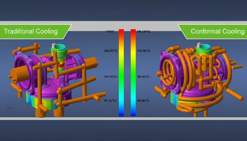
Conformal Cooling Channels
Conformal cooling channels follow the exact contour of the mold cavity, maintaining a uniform distance from the part surface regardless of how complex the geometry is. They’re manufactured using metal 3D printing (selective laser melting) or, in some cases, by machining grooves into split inserts and sealing them with conformal copper alloys.
Il risultato è un raffreddamento notevolmente più uniforme. Le aree che sarebbero punti caldi in uno stampo a foratura rettilinea — cavità profonde, nervature sottili, superfici curve — ricevono la stessa intensità di raffreddamento delle aree piane. Su un alloggiamento complesso per dispositivo medico con pareti di 1,2 mm, il raffreddamento conforme può ridurre il tempo di ciclo del 20–35% rispetto alla foratura convenzionale.
The tradeoff is cost. A conformal-cooled insert costs 2–4× more than a drilled equivalent because of the additive manufacturing process. But for high-volume tools running 500K+ shots, the cycle time savings pay for the difference within weeks. We’ve also seen conformal cooling reduce warpage by up to 50% on asymmetrical parts because the temperature gradient across the part is smaller.
Conformal channels can also have variable cross-sections and non-circular profiles, which is impossible with conventional drilling. This allows mold designers to optimize flow velocity and heat transfer coefficient independently in different regions of the same insert — a level of thermal control that straight-drill circuits simply cannot match.
Cooling Mediums: Water, Oil, and Air
Water is the cooling medium in over 90% of injection molding operations worldwide. It offers high thermal conductivity3 (0.6 W/(m·K)), low cost, easy availability, and precise temperature control between 10°C and 90°C using a thermolator or cooling tower. Water also has a high specific heat capacity, meaning it absorbs a large amount of thermal energy per unit volume.
Oil cooling is used when the mold needs to run hotter than 90°C — common with high-performance engineering resins like PEEK (mold temp 160–200°C) or polysulfone (mold temp 120–160°C). Oil systems operate up to 300°C but have roughly 4× lower thermal conductivity than water (0.15 vs 0.6 W/(m·K)) and require more energy to circulate. They also introduce fire risk at high temperatures and add significant maintenance overhead compared to water systems.
Air cooling is rarely used as a primary system because air’s thermal conductivity is roughly 25× lower than water (0.025 vs 0.6 W/(m·K)). You’ll see it as a supplement — compressed air blowing on specific hot spots, or in very low-volume prototype molds where the cost of a water circuit isn’t justified. Some molds use air assist on ejector pins to cool deep cores that water can’t easily reach.
| Proprietà | Water | Oil | Aria |
|---|---|---|---|
| Conduttività termica | 0.6 W/(m·K) | 0.15 W/(m·K) | 0.025 W/(m·K) |
| Temperature Range | 10–90°C | 50–300°C | Ambient only |
| Costo | Basso | Medio | Very Low |
| Typical Use | Most applications | High-temp resins | Prototype only |
How Cooling Affects Product Quality and Cycle Time
Cooling system performance directly impacts three quality metrics: dimensional accuracy, surface appearance, and mechanical consistency. Uneven cooling — where one area of the part solidifies faster than another — causes internal stresses that lead to warpage, sink marks, and shrinkage variation across the part.
A temperature difference of just 10°C across the part surface can cause measurable dimensional drift of 0.1–0.3mm on a 100mm feature. For tight-tolerance automotive or medical parts where ±0.05mm is the acceptance window, that’s a rejection. And the problem gets worse over a production run — as the mold heats up from continuous cycling, thermal gradients increase, and parts that passed inspection in the first hour start drifting out of spec.
On cycle time: in a typical injection molding cycle, filling takes 1–3 seconds, packing takes 2–5 seconds, and cooling takes 10–40 seconds. Ejection and mold open/close add another 3–8 seconds. Cooling dominates the total cycle, accounting for 70–80% of the elapsed time in most applications.
The math is straightforward. If your current cycle is 20 seconds and you reduce cooling time by 3 seconds (15% improvement), on a 1-million-shot tool you save 833 hours of machine time. At a machine rate of $30–50/hour, that’s $25,000–$41,000 in reduced production cost — more than the price premium for better cooling channels in most cases. This is why optimizing cooling is almost always the highest-ROI improvement you can make to a production mold.
Design Principles for Mold Cooling Systems
Mold cooling design is governed by five core principles. Maximize channel count, keep consistent cavity distance, align coolant flow with material flow, limit inlet-outlet temperature delta to 3–5°C, and ensure turbulent flow in every circuit. More channels at smaller spacing always outperform fewer large channels.
First, maximize channel count and minimize channel spacing. More channels at smaller pitch distances produce a more uniform cavity surface temperature. The practical limit is mold strength — you can’t put channels so close together that the steel between them becomes a weak point. As a rule of thumb, the land width between two parallel channels should be at least equal to the channel diameter.
Five Rules for Effective Cooling Layout
Second, maintain consistent distance from channel to cavity surface — ideally 12–15mm. Closer than 10mm creates cold spots and risks steel cracking under injection pressure; farther than 20mm reduces cooling efficiency significantly.
Third, align coolant flow direction with material flow. The coolant inlet should be near the gate, where the plastic is hottest. This ‘water-material parallel’ approach ensures the coolest water hits the hottest plastic first, then progressively warmer coolant handles the cooler areas of the part. The result is more uniform overall solidification and significantly less warpage.
Fourth, keep the temperature difference between coolant inlet and outlet below 3–5°C. A larger temperature gap means the mold surface near the outlet is significantly warmer than near the inlet — creating the exact kind of uneven cooling that causes warpage and dimensional variation.
Fifth, specify turbulent flow in every circuit — not just adequate flow rate, but actual Reynolds numbers above 4000. Laminar flow (Reynolds < 2300) creates a slow-moving boundary layer along the channel wall that acts as thermal insulation. In practice, this means you need a minimum coolant velocity of 0.5–1.0 m/s through a 10mm channel, which requires a pump capable of delivering 3–5 liters per minute per circuit. Many production molds have channels that appear to be flowing well (you can see water moving) but are actually in the transitional flow regime (Reynolds 2300–4000), leaving 15–20% of potential cooling capacity on the table.
These four principles apply regardless of which channel type you choose. Even a straight-drill mold performs well when the channels are properly spaced, correctly distanced from the cavity, and running turbulent coolant flow. The channel type determines the ceiling of cooling performance — the design principles determine how close you get to that ceiling.
At ZetarMold, our 8 senior engineers review every cooling layout in DFM before steel cutting. On a recent automotive interior program, catching a 20mm channel-to-cavity distance (too far) during DFM saved an estimated 4 seconds per cycle — worth over $120,000 across the tool’s production life.

When to Upgrade from Straight-Drill to Conformal Cooling
Upgrade to conformal cooling when your part has complex geometry — wall variation over 3:1, deep features above 50mm, thin walls under 1.5mm, or annual volume exceeding 200K shots. The decision comes down to part geometry, production volume, and cycle-time cost at your specific machine rate.
Upgrade when: the part has wall thickness variation greater than 3:1, deep features (>50mm) that straight-drill can’t reach, thin walls (<1.5mm) requiring fast and uniform cooling, or annual production volume exceeding 200K shots. In any of these cases, the cycle time savings from conformal cooling will typically pay back the tooling premium within the first production run.
Stay with straight-drill when: the part is simple and flat, wall thickness is uniform, and production volume is under 100K shots. Adding conformal cooling to a simple mold is over-engineering — the cycle time improvement might be only 5–8%, which doesn’t justify the 2–4× cost premium on the insert.
Baffles and spirals fill the middle ground. If you have a moderately complex part but can’t justify conformal cooling cost, baffle channels on deep cores plus spiral channels on cylindrical features will capture 60–70% of the cycle time benefit at 20–30% of the cost premium. This hybrid approach is what we recommend for most mid-volume automotive and consumer electronics programs.
The break-even calculation is simple: (tooling cost premium) ÷ (per-part cycle time savings × machine rate). If the result is less than your expected production volume, conformal cooling pays for itself. If it’s more, stick with conventional channels and invest the savings elsewhere.
“Conformal cooling channels can reduce cycle time by 20–35% on parts with complex geometry.”Vero
By maintaining uniform distance from the cavity surface, conformal channels eliminate the hot spots that limit ejection timing in conventionally drilled molds. Documented cases show 28% cycle time reduction on 1.2mm wall ABS housings.
"Il raffreddamento ad olio è sempre migliore del raffreddamento ad acqua perché l'olio può raggiungere temperature più elevate."Falso
L'olio ha una conduttività termica circa 4 volte inferiore all'acqua (0,15 vs 0,6 W/(m·K)), il che significa un'estrazione del calore più lenta per unità di flusso. L'olio è superiore solo quando la resina richiede temperature dello stampo superiori a 90°C — per la maggior parte delle applicazioni, l'acqua raffredda più velocemente, a minor costo e in modo più sicuro.
Comprendere questi fatti aiuta a porre le domande giuste quando si valutano i preventivi per gli stampi da parte dei fornitori. Molti costruttori di stampi optano per il raffreddamento a canali diritti perché è l'opzione più economica, non perché sia la scelta migliore per la geometria del pezzo. Chiedere specificamente sul tipo di canale di raffreddamento, sulla distanza canale-cavità e sul numero di Reynolds durante la fase DFM distingue uno stampo ben progettato da uno che costerà in scarti e perdita di produttività durante tutta la sua vita produttiva. Se il fornitore non può spiegare la propria strategia di raffreddamento in termini di questi principi fondamentali, è un campanello d'allarme da approfondire prima di impegnarsi per la costruzione dello stampo.
"L'ingresso del refrigerante dovrebbe essere posizionato vicino all'area del punto di ingresso per un'ottimale uniformità di raffreddamento."Vero
Posizionare l'acqua più fredda vicino al punto di ingresso — dove la plastica è più calda — allinea il flusso del refrigerante con il flusso del materiale. Questo approccio 'acqua-materiale parallelo' riduce il gradiente di temperatura sul pezzo del 40–60%, prevenendo deformazioni dovute a raffreddamento differenziale e consentendo un'espulsione più precoce del pezzo.
"I canali di raffreddamento diritti funzionano ugualmente bene per tutte le geometrie dei pezzi."Falso
I canali diritti non possono seguire caratteristiche curve o profonde della cavità, lasciando punti caldi in aree come nervature alte, tasche profonde e superfici curve. Per pezzi con variazione dello spessore di parete superiore a 3:1 o caratteristiche profonde oltre 50mm, sono necessari canali a deflettore o conformi per ottenere un'uniformità di raffreddamento accettabile.
Domande frequenti
Domande frequenti
Qual è il sistema di raffreddamento più comune utilizzato negli stampi ad iniezione?
I canali di raffreddamento ad acqua diritti-forati sono il sistema più comune, utilizzato in oltre l'80% degli stampi di produzione in tutto il mondo. Sono l'opzione a costo più basso e funzionano bene per pezzi con geometrie relativamente semplici e piatte dove è possibile mantenere una distanza uniforme canale-cavità in tutto lo stampo. Per pezzi più complessi, i costruttori di stampi integrano tipicamente i circuiti diritti-forati con deflettori o inserti conformi nelle aree critiche. L'acqua a 10–80°C è il refrigerante standard, fatta circolare da un'unità di controllo della temperatura (TCU) che mantiene la temperatura target dello stampo entro ±1°C.
Quanto costa aggiungere il raffreddamento conforme a uno stampo?
Il raffreddamento conforme tipicamente aggiunge un costo di 2–4 volte superiore per l'inserto raffreddato rispetto alla foratura convenzionale, a causa del processo di stampa 3D metallica (fusione selettiva laser) necessario per produrre i canali. Per un inserto di produzione standard che costa 3.000–5.000 € con foratura convenzionale, la versione conforme potrebbe costare 8.000–15.000 €. Tuttavia, per stampi ad alto volume che producono oltre 500.000 pezzi, il risparmio di tempo di ciclo del 20–35% di solito recupera questo premio entro le prime serie di produzione. Il periodo esatto di ammortamento dipende dal costo orario della macchina e dalla geometria specifica del pezzo stampato.
Quale temperatura dovrebbe avere l'acqua di raffreddamento?
La temperatura dell'acqua di raffreddamento dipende dal materiale stampato ed è specificata dal produttore della resina. Gli intervalli comuni includono 10–30°C per resine comuni come PP e PE (cristallizzazione rapida), 40–60°C per resine amorfe come ABS e PC e 60–80°C per resine tecniche come PA66 e PBT che richiedono stampi più caldi per una corretta cristallizzazione. La scheda tecnica del produttore del termoplastico indica sempre l'intervallo di temperatura dello stampo consigliato. Funzionare troppo freddi può causare segni di flusso e alte tensioni residue; funzionare troppo caldi prolunga inutilmente il tempo di ciclo.
Perché l'acqua è migliore dell'aria per il raffreddamento degli stampi?
L'acqua ha una conducibilità termica circa 25 volte superiore a quella dell'aria (0,6 contro 0,025 W/(m·K)), il che significa che estrae calore dallo stampo in modo molto più efficiente per unità di flusso. L'acqua ha anche una capacità termica specifica molto più elevata, consentendole di assorbire più energia termica prima che la sua temperatura aumenti significativamente. Inoltre, l'acqua consente un controllo preciso della temperatura tramite termoregolatori (±1°C di precisione), mentre il raffreddamento ad aria non offre quasi alcuna capacità di regolazione della temperatura. L'aria viene utilizzata solo come integrazione in scenari molto specifici — stampi per prototipi, raffreddamento localizzato di punti caldi o dove il rischio di perdite d'acqua è inaccettabile.
In che modo un raffreddamento insufficiente causa deformazioni nei pezzi stampati a iniezione?
Un raffreddamento non uniforme crea gradienti di temperatura attraverso il pezzo: una regione si solidifica e si restringe mentre un'altra è ancora calda e si contrae a una velocità diversa. Questo restringimento differenziale genera tensioni interne che deformano il pezzo rispetto alla forma prevista una volta espulso e raffreddato a temperatura ambiente. Una variazione di temperatura di soli 10°C sulla superficie della cavità può causare una deriva dimensionale di 0,1–0,3 mm su una caratteristica di 100 mm. L'effetto è più pronunciato nei pezzi con spessore di parete non uniforme, sezioni lunghe e sottili o geometria asimmetrica — esattamente i pezzi che richiedono la progettazione più attenta dei canali di raffreddamento per compensare.
Qual è la distanza ideale tra i canali di raffreddamento e la superficie della cavità?
La distanza consigliata dalla parete del canale di raffreddamento alla superficie della cavità è di 12–15 mm, o circa 1,5–2,0 volte il diametro del canale per fori standard da 8–10 mm. Questo intervallo bilancia l'efficienza di estrazione del calore con l'integrità strutturale dello stampo. Una distanza inferiore a 10 mm crea punti freddi localizzati sulla superficie del pezzo e rischia di provocare crepe nell'acciaio sotto le alte pressioni di iniezione (tipicamente 80–140 MPa). Una distanza superiore a 20 mm riduce significativamente l'efficienza di raffreddamento — l'acciaio agisce come isolante termico e si finisce per far circolare più refrigerante con rendimenti decrescenti sulla rimozione effettiva del calore dalla cavità.
È possibile combinare diversi tipi di canali di raffreddamento in un unico stampo?
Sì, combinare i tipi di canali è una pratica standard negli stampi di produzione ed è spesso l'approccio più conveniente. Una configurazione comune utilizza circuiti a foratura dritta per le aree piane del pezzo, canali a deflettore nei nuclei profondi e nelle nervature alte, canali a spirale attorno alle caratteristiche cilindriche e inserti conformi solo nelle regioni più complesse o termicamente critiche. Questa strategia ibrida bilancia costo e prestazioni senza sovra-ingegnerizzare l'intero utensile. In ZetarMold, specifichiamo questo approccio misto su circa il 60% degli stampi di produzione — cattura il 70–80% delle prestazioni termiche del raffreddamento conforme completo a un sovrapprezzo del 30–40%.
-
tempo di ciclo: Il tempo di ciclo è la durata totale di un ciclo completo di stampaggio a iniezione, misurato in secondi, dalla chiusura dello stampo all'espulsione del pezzo. ↩
-
conformal cooling: Raffreddamento conforme si riferisce a canali di raffreddamento che seguono il contorno della superficie della cavità dello stampo, tipicamente realizzati utilizzando stampa 3D metallica o produzione additiva. ↩
-
thermal conductivity: La conducibilità termica è una proprietà del materiale misurata in W/(m·K) che quantifica la velocità con cui il calore si trasferisce attraverso una sostanza. ↩


