 콘텐츠로 건너뛰기

You just set up a new mold on a 200T machine. The first three shots look fine, then short shots start appearing. You tweak the holding pressure, the temperature goes up 5 degrees, and now you have flash. Sound familiar? Most injection molding problems on the production floor trace back to a handful of machine settings that operators either overlook or set by habit rather than by logic.
This article walks through 18 practical tips that actually matter — the ones we use every day running complete injection molding guide 47대의 기계에서 얻은 경험입니다. 이론 자체를 위한 이론은 없습니다. 안정적인 가동과 긴급 대응 사이의 차이를 만드는 것들만 있습니다.
- Back pressure of 5–15 bar gives consistent melt; above 20 bar adds wear with diminishing returns.
- Screw cushion of 3–9 mm must stay constant — even a 1 mm drift changes your part weight.
- Melt temperature should be measured at the nozzle, not assumed from cylinder settings.
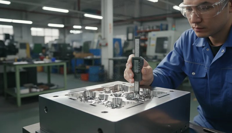
- Mold temperature variation of ±2 °C can shift part dimensions by 0.1–0.3 mm on engineering resins.
- Cooling uniformity — not speed — is the real driver of dimensional stability.
What Are the Most Critical Machine Settings for Injection Moulders?
The most critical machine settings for injection moulders are the main categories or options explained in this section. If you are comparing vendors or planning procurement, our 사출 성형 공급업체 sourcing guide covers RFQ prep, qualification, and commercial risk checks.
The five settings that cause 80% of production issues are 배압1, screw speed, cushion2, melt temperature, and mold temperature. If you get these right, most defects — short shots, sink marks, dimensional drift — resolve themselves without chasing secondary parameters.
47대의 기계에서 400종 이상의 소재를 가공한 경험상, 가장 조정이 부족한 설정은 백압입니다. 대부분의 작업자는 공장 출고 시 기본값으로 두는데, PP나 PE에는 괜찮지만, 유리 섬유 강화 나일론이나 고온 폴리카보네이트의 경우 품질을 제대로 끌어내지 못하게 됩니다.
Think of these five parameters as a system, not independent knobs. Increasing back pressure adds shear heat, which means you may need to lower barrel temperatures. Increasing screw speed does the same. Every change cascades. The best operators adjust one parameter at a time and observe the result for at least 10 consecutive shots before making the next change.
Before diving into each setting in detail, here is the quick framework we use on our production floor: first set temperatures (barrel and mold), then set pressures (back pressure and holding), then set speeds (screw and injection), then fine-tune times (holding and cooling). This sequence minimizes the number of variables changing at once and makes troubleshooting systematic.

How Should You Select and Maintain Injection Nozzles?
Open nozzles work for 90% of production runs. They are cheaper, simpler, and have fewer dead spots where material can degrade. Use closed (shut-off) nozzles only when you are running low-viscosity resins like PA6 or POM on a machine without screw retraction — and even then, the shut-off valve needs inspection every 2,000 cycles.
The nozzle tip radius must be 0.5 mm smaller than the sprue bushing radius. A 1 mm mismatch in diameter sounds trivial, but it causes drool, stringing, and cold slugs in the runner. We check nozzle alignment every mold change — it takes 30 seconds with a height gauge and saves hours of defects.
For mixing-sensitive materials (masterbatch color changes, flame retardant blends), consider adding a static mixer between the barrel and nozzle. It adds 50 mm to the melt path but cuts color streak defects by roughly 60%. The trade-off is a slight increase in pressure drop — about 10–15 bar — which you compensate by raising injection pressure.
Nozzle maintenance is one of those tasks that gets skipped when production is busy. But a nozzle with carbonized residue buildup changes the effective orifice diameter, which changes shear rate and melt temperature at the gate. We schedule nozzle pulls and cleaning every 3,000 cycles for engineering resins, every 5,000 for commodity materials.
Why Does Back Pressure Make or Break Melt Quality?
이 섹션은 백압이 용융 품질을 결정짓고 비용, 품질, 시기, 조달 리스크에 미치는 영향에 관한 것입니다. 백압은 사출 성형기에서 가장 과소평가된 설정으로, 용융 균질성, 색상 일관성, 샷 간 중량 안정성을 직접 제어합니다. 대부분의 엔지니어링 수지에서 최적 범위는 5~15 bar입니다. 너무 낮으면(0~3 bar) 녹지 않은 펠릿, 색상 소용돌이, 불일치한 샷 중량이 발생합니다. 너무 높으면(25+ bar) 연장된 주기 시간3, excessive shear heat, and accelerated screw wear.
The practical range for most engineering resins is 5–15 bar. Start at 8 bar, shoot an air shot, and check for consistent extrusion. If the melt looks milky or has visible pellets, increase in 2-bar increments. For PC or PEEK, you may need 12–18 bar because of their high viscosity.
One mistake we see often: operators increasing back pressure to compensate for a worn screw. That works temporarily but the real fix is a screw and barrel inspection. If your cushion is drifting and the recovery time keeps lengthening, the screw flight is probably worn beyond 0.5 mm clearance. At that point, no amount of back pressure adjustment will restore process consistency.
Another subtle issue: back pressure interacts with screw decompression (suck-back). If you run high back pressure and then apply aggressive suck-back, you can pull air bubbles into the melt. The fix is simple — either reduce back pressure slightly, or reduce suck-back distance to 2–3 mm. On vented-barrel machines running hygroscopic resins, this combination is especially important to control.
“Increasing back pressure from 3 bar to 10 bar can reduce color swirl defects by over 50% in ABS parts.”True
Higher back pressure improves dispersion of colorant in the melt by forcing the material through tighter clearances between screw flights and barrel wall, producing more consistent pigmentation throughout the shot volume.
“Higher back pressure always produces better part quality.”False
Excessive back pressure (above 20 bar for most resins) generates too much shear heat, degrades the polymer chains, increases cycle time due to longer screw recovery, and accelerates screw and barrel wear. The optimum is material-specific and typically between 5 and 15 bar.
How Does Screw Speed Affect Plasticizing and Part Consistency?
스크류 속도는 용융 온도 균일성과 색상 일관성을 직접 결정합니다. 대부분의 기계에서 50~100 rpm이 최적 범위입니다. 빠른 회전은 더 많은 마찰열을 발생시키지만 용융물의 균일성이 떨어집니다. 느린 회전은 혼합은 더 잘 되지만 금형이 열리기 전에 회수(리커버리)가 완료되지 않을 수 있습니다. 핵심은 스크류 속도를 조정하여 회수가 금형 개방 1~2초 전에 끝나도록 하는 것입니다.
The rule of thumb: adjust screw speed so that recovery finishes 1–2 seconds before mold open. If the screw is still recovering when the mold opens, you are losing cooling time and creating unnecessary pressure on the operator. If recovery finishes way before mold open, you can slow the screw and reduce shear heating.
Different materials demand different screw speeds. PVC and PMMA are shear-sensitive — keep screw speed below 60 rpm to prevent degradation. POM and PA66 can tolerate 80–120 rpm. PEEK and LCP, despite their high melt temperatures, actually benefit from moderate screw speed (40–80 rpm) because their low viscosity means less shear heating is needed.
Screw speed also affects color consistency. At very low speeds (120 rpm on small machines), you can get localized overheating that causes color streaks or burns. The middle ground, combined with proper back pressure, gives the best results for both melt quality and color uniformity.

What Is Screw Cushion and Why Must It Stay Constant?
공정 시트에 용융 온도 240°C와 금형 온도 60°C로 표기되어 있고 부품 상태가 양호하다면, 다음 생산 시 '감각에 의한 최적화'를 시도하지 마십시오. 문서화되고 재현 가능한 공정 범위는 작업자의 판단보다 항상 우월합니다. 이것이 바로 여러 교대조에 걸친 120명 이상의 생산 작업자들이 일관된 품질을 유지하는 방법입니다.
Modern machines can hold cushion to ±0.1 mm. If you see ±1 mm variation, check for: (1) non-return valve leakage, (2) inconsistent feed, (3) worn barrel in the metering zone. In our shop, cushion consistency is the first thing we check when a customer reports dimensional variation on a part that used to run fine.
Screw retraction (suck-back) is related but different. After injection and before mold opening, the screw pulls back slightly to decompress the melt and prevent nozzle drool. Typical suck-back is 3–5 mm. On vented barrels running hygroscopic materials, reduce suck-back to 2 mm — pulling air into the melt creates bubbles that appear as splay on the part surface.
When setting cushion, remember: the cushion value you program into the machine controller assumes the screw zero point is correct. After a screw pull and cleaning, always re-zero the screw position. We have seen cases where a 3 mm cushion was actually 0 mm because the zero point shifted during reassembly — resulting in no holding pressure transfer and 100% short shots on the first setup attempt.
How Do You Calculate and Verify Plasticizing Capacity?
Plasticizing capacity³ is the rate at which your machine can uniformly melt material, expressed in kg/h of PS equivalent. Every machine has this spec in the manual. The problem is that most people never verify whether their actual cycle time exceeds the machine’s melting capability.
Use this formula: tmin = (total shot weight in g × 3600) ÷ (plasticizing rate in kg/h × 1000). If your actual cycle time is shorter than tmin, the machine cannot melt material fast enough — you will see inconsistent viscosity, short shots on later cavities, and surface gloss variation across the shot.
This is especially critical for multi-cavity molds with high shot weights. If your calculation shows you are at 85% or more of plasticizing capacity, you should either extend cooling time, reduce cavities, or move to a larger machine. Running at the edge of plasticizing capacity is a recipe for scrap.
Another consideration: plasticizing capacity degrades over the life of the machine. A worn screw with increased flight clearance cannot generate the same shear and compression as a new one. If you notice that parts from an older machine consistently show more color variation or unmelt than the same mold on a newer machine, have the screw and barrel measured. Wear of 0.3–0.5 mm on flight diameter can reduce effective plasticizing capacity by 15–25%.

Why Is Melt Temperature Management Critical?
The barrel temperature settings on your machine are not the melt temperature. They are heater band setpoints. The actual melt temperature is affected by screw speed, back pressure, shot volume, and residence time⁵. The only reliable way to know your melt temperature is to measure it at the nozzle with a pyrometer or by air-shot method.
For air shots, wear heat-resistant gloves and a face shield. Extrude a small amount of melt into a metal container and insert a preheated thermocouple probe. The reading should be within ±5 °C of the material supplier’s recommended range. If it is 10–15 °C higher, your shear heating from screw speed and back pressure is adding too much energy — reduce one or both.
Temperature profiling matters too. Set the rear zone (feed) coolest to prevent premature melting and bridging. Increase progressively toward the nozzle. The nozzle tip can be set 5–10 °C lower than the front zone to prevent drool. If you have no experience with a particular resin, always start at the lowest recommended temperature and work up in 5 °C increments.
ZetarMold의 상하이 공장에는 90T부터 1850T까지 47대의 사출 성형기가 가동 중입니다. 2005년부터 20년 이상의 성형 경험과 8명의 선임 금형 엔지니어를 보유한 우리는 모든 생산 설정의 일환으로 용융 온도 검증을 표준화합니다. 첫 샘플 승인 전에 작업자는 공정 시트의 ±5 °C 이내에서 실제 노즐 용융 온도를 확인해야 합니다.
“Measuring melt temperature by air shot is more accurate than relying on barrel heater setpoints.”True
Barrel thermocouples are embedded in the steel wall and measure steel temperature, not polymer temperature. Shear heating from screw rotation and back pressure can raise actual melt temperature 10–30 °C above the barrel setpoint, making direct measurement essential for process control.
“All heater zones should be set to the same temperature for simplicity.”False
A proper temperature profile starts cooler at the feed zone to prevent bridging, increases through the transition zone for progressive melting, and may be slightly lower at the nozzle tip to prevent drool. Uniform settings across all zones cause feed problems and inconsistent melting.
What About Residence Time and Material Degradation?
사출 성형에서 열 분해의 주된 원인은 체류 시간(플라스틱이 가열된 배럴에 머무르는 시간)입니다. 모든 고분자는 주어진 온도에서 최대 안전 체류 시간이 있으며, 이를 초과하면 분자량 감소, 변색, 가스 발생, 육안 검사는 통과하지만 실제 사용 중 고장나는 약화된 부품이 생깁니다.
Calculate it: tresidence = (barrel volume in g × cycle time in s) ÷ (shot weight in g × 300). This gives a rough number. The real number is always longer because material hangs up in dead spots. For precision work, do a color purge test: add colored pellets and time how long until color appears in the shot.
The biggest risk: large barrel machines running small shot weights. If your shot uses less than 30% of barrel capacity, your residence time can easily exceed safe limits. The fix is either use a smaller machine or purge the barrel every 15–20 minutes during extended runs. For materials like POM or PVC that degrade aggressively, shot utilization below 20% should be avoided entirely.
Watch for early degradation signs: silver streaks (splay), light brown or yellowish discoloration, a faint acrid smell at the nozzle, or a gradual decrease in part weight without any process changes. These all point to material breaking down in the barrel. When you see them, stop and purge immediately — continuing to run degrading material contaminates the barrel and makes the problem worse for subsequent shots.
How Should Mold Temperature Be Controlled?
이 섹션은 금형 온도 제어와 그에 따른 비용, 품질, 시기, 조달 리스크의 영향에 관한 것입니다. 금형 온도는 캐비티 표면의 접촉식 온도계로 확인해야 하며, 5~15 °C 차이가 날 수 있는 온도 조절기 표시를 믿어서는 안 됩니다. 정밀 공차 부품의 경우 각 회로마다 개별 온도 조절기를 사용하여 변동을 ±2 °C 이내로 유지하세요. 금형 온도는 표면 마감, 결정화도, 수축, 뒤틀림을 직접 제어합니다.
Always verify mold temperature with a contact thermometer on the cavity surface, not by reading the thermolator display. The display shows coolant temperature at the unit, which can differ from the actual cavity surface by 5–15 °C depending on circuit length, flow rate, and scale buildup inside the channels.
For tight-tolerance parts, keep mold temperature variation within ±2 °C. On our floor, this means using individual thermolators per mold circuit for critical molds — not daisy-chaining multiple circuits to one unit. Yes, it costs more in equipment. But rework and scrap from dimensional drift cost even more, especially on multi-cavity molds where one circuit running 5 °C hotter shifts half the cavities out of spec.
A common mistake: setting mold temperature based on what worked for a similar material on a different mold. Mold size, circuit layout, and wall thickness all affect what temperature the cavity surface actually reaches. A 60 °C setting on a small, simple mold might produce 55 °C at the surface, while the same setting on a large mold with long cooling circuits might only reach 42 °C. Measure every mold, every time.
Why Is Uniform Cooling More Important Than Fast Cooling?
균일한 냉각이 빠른 냉각보다 더 중요한 이유는 비용, 품질, 생산량, 적용 분야의 절충점이 이를 뒷받침하기 때문입니다. 대부분의 작업자는 금형을 가능한 한 빨리 냉각하여 complete injection mold design guide. Speed matters, but uniformity matters more. Uneven cooling causes differential shrinkage, which causes warpage, internal stress, and out-of-tolerance dimensions — even if the cycle time looks great on paper.
The counterintuitive technique: run cooler water on the core (inside of the part) and warmer water on the cavity (outside). This equalizes the cooling rate between thick and thin sections. For flat, precision parts — think optical lenses, sealing surfaces, or mating housings — this alone can cut warpage by 40–60%.
Check cooling circuit flow rate at every mold change. A circuit that flowed 12 L/min last run might be down to 4 L/min because of scale buildup. Low flow means turbulent flow becomes laminar, heat transfer drops by 30–50%, and your carefully set temperatures become meaningless. If flow drops below 60% of original, clean or replace the circuit before running production.
For multi-cavity molds, balancing cooling across cavities is critical. The cavity closest to the water inlet always cools fastest. Use flow restrictors or individual circuits per cavity to equalize cooling. On eight-cavity molds, we have measured 8 °C temperature difference between the first and last cavity on a single series circuit — enough to produce measurable dimensional variation between parts.
What Are the Most Overlooked Tips for Injection Moulders?
The most overlooked tips for injection moulders are the main categories or options explained in this section. Beyond the five core settings, several secondary factors catch people off guard on a regular basis:
Tip 14: Check the non-return valve. The ring-type check valve at the screw tip wears gradually. When clearance exceeds 0.1 mm, you lose holding pressure consistency. Inspect every 500,000 shots or whenever cushion variation exceeds ±0.5 mm. A replacement non-return valve costs a few hundred dollars; running production with a worn one costs thousands in scrap.
Tip 15: Vent the mold properly. Trapped air causes burning, dieseling, and short shots in dead-end areas. Vents should be 0.01–0.02 mm deep at the parting line and clean — not polished shut from previous flash. Add vent pins at the end of flow paths and at blind pockets where air naturally traps.
Tip 16: Dry the material correctly. Hygroscopic resins (PC, Nylon, PET, TPU) absorb moisture that causes splay, molecular degradation, and weakened weld lines. PC needs drying at 120 °C for 3–4 hours with dew point below –20 °C. A material that ‘looks dry’ is not dry — verify with a moisture analyzer before every production run.
Tip 17: Record everything. Every parameter change, every temperature reading, every cavity dimension on the first 10 shots. When problems appear on day 3 of production, you will need that baseline. We require all operators to fill out a setup log before first article approval. The 10 minutes spent on documentation saves hours of finger-pointing later.
Tip 18: Trust the data, not intuition. If the process sheet says 240 °C melt and 60 °C mold, and the parts look good — do not ‘optimize by feel’ on the next run. Documented, repeatable process windows beat operator judgment every time. That is how you get consistent quality across 120+ production workers on multiple shifts.
What Are the Most Frequently Asked Questions About Injection Molding Tips?
What is the ideal back pressure for injection molding?
대부분의 엔지니어링 수지에 이상적인 백압은 5~15 bar입니다. ABS나 PP와 같은 범용 소재는 8 bar에서 시작하세요. 폴리카보네이트나 PEEK와 같은 고점도 수지의 경우 12~18 bar로 높이세요. 20 bar를 초과하면 품질 향상 효과가 줄어드는 반면 스크류 마모를 가속화하고 사이클 시간을 연장시킵니다. 항상 에어 샷 검사로 결과를 확인하세요. 47대의 기계에서 400종 이상의 소재를 가공한 경험으로, 백압을 8~12 bar 사이로 유지하면 약 80%의 생산 작업을 문제없이 처리할 수 있습니다.
How much screw cushion should I maintain?
Maintain 3 mm cushion on machines below 300T and 6–9 mm on machines above 1000T. The key metric is consistency — cushion should not vary more than ±0.5 mm shot to shot. Larger variation typically indicates a worn non-return valve, inconsistent material feed, or barrel wear in the metering zone. Check and address the root cause rather than compensating with other parameters. In our facility, operators log cushion values every 50 shots; any trend exceeding ±1 mm triggers a valve inspection before the run continues.
How do I verify actual melt temperature?
Use the air-shot method with a preheated pyrometer probe. Extrude a small melt sample into a metal container wearing heat-resistant gloves and a face shield, then insert the probe immediately. The reading should be within ±5 °C of the material datasheet range. Barrel heater setpoints are not reliable melt temperature indicators because shear heating from screw rotation can raise actual temperature 10–30 °C above setpoints. For critical jobs, we recommend taking air-shot readings at the start of each shift and after any speed or back pressure change.
Why are my injection molded parts warping?
Warping occurs when cooling rate variation exceeds 15 °C across the part, typically from non-uniform wall thickness exceeding a 3:1 ratio or inadequate cooling circuit design. Fix cooling uniformity first by running cooler water on the core side and warmer water on the cavity side. This differential cooling technique reduces warpage by 40–60% on flat precision parts without changing cycle time significantly. Also check that gate placement supports balanced fill — asymmetric filling creates internal stresses that amplify warpage even when cooling is uniform.
How often should injection molding nozzles be inspected?
Inspect open nozzles every mold change for alignment and tip radius wear — the tip radius should be 0.5 mm smaller than the sprue bushing radius. Inspect shut-off (closed) nozzles every 2,000 cycles for valve seating integrity. Schedule nozzle pulls and cleaning every 3,000 cycles for engineering resins and every 5,000 cycles for commodity materials to prevent carbonized residue buildup. During peak production months, our team pulls nozzles weekly on machines running glass-filled nylon, as abrasive wear accelerates significantly with filled compounds.
What happens if residence time is too long in the barrel?
Excessive residence time causes thermal degradation: molecular weight drops, discoloration appears (yellow or brown tint), gas generation increases, and mechanical properties decline. The risk is highest when shot weight uses less than 30% of barrel capacity. Purge the barrel every 15–20 minutes during such runs, or move to a smaller machine. Watch for early signs like silver streaks or acrid smell. Calculate residence time using barrel volume divided by shot volume multiplied by cycle time — if it exceeds 5 minutes for most engineering resins, you are in the degradation zone.
How do I calculate if my machine has enough plasticizing capacity?
Divide total shot weight in grams by 1000, multiply by 3600, then divide by the machine’s rated plasticizing capacity in kg/h. The result is your minimum cycle time in seconds. If your actual cycle time is shorter than this calculated minimum, the machine cannot melt material fast enough for consistent quality — you will see viscosity variation and surface defects. Always include a 10–15% buffer above the calculated minimum to account for material batch variation and ambient temperature changes that affect real-world throughput.
Should all mold cooling circuits use the same water temperature?
No. For parts with significant wall thickness variation, use differential cooling: cooler water (10–15 °C lower) on the core and warmer water on the cavity side. This equalizes cooling rates between thick and thin sections, reducing warpage by 40–60%. For multi-cavity molds, use individual circuits per cavity or flow restrictors to balance cooling across all cavities. At our Shanghai facility, we verify cooling circuit flow rates at every mold change using a flow meter — a circuit flowing below 80% of its design rate gets descaled or replaced before production starts.
-
back pressure: Back pressure is the resistance applied to the screw during its recovery stroke, measured in bar or MPa, which controls melt homogeneity and mixing quality in the injection cylinder. ↩
-
cushion: Cushion, also called screw cushion or pad, refers to the small volume of molten plastic remaining in front of the screw tip at the end of injection, typically 3–9 mm, ensuring consistent pressure transfer to the cavity. ↩
-
cycle time: Cycle time is the total elapsed time from the start of one injection molding shot to the start of the next, measured in seconds, encompassing injection, holding, cooling, and ejection phases. ↩


