 Zum Inhalt springen

– MUD (Master Unit Die) inserts are interchangeable cavity blocks that fit into a standardized master frame, reducing tooling cost by 40–70% compared to dedicated full molds for each part.
– Proper draft1 angles (1–3° minimum on most features), uniform wall thickness (1.5–4 mm for most materials), and adequate venting are the three most critical design guidelines for MUD insert success.
– MUD inserts are sized in standard families (typically 2×3 in., 3×4 in., 4×5 in., and 5×7 in. for common systems like DME and Hasco), so part geometry must fit within available insert dimensions.
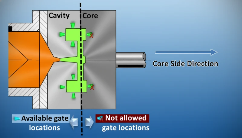
– Gate placement in MUD inserts is constrained by the master frame’s runner system—understanding frame gate geometry early prevents costly redesigns.
– Conformal cooling is increasingly integrated into MUD inserts using 3D-printed metal technology, improving thermal uniformity and reducing cycle time by 20–35%.
What Is a MUD Insert System and Why Does It Matter for Tooling Cost?
A MUD (Master Unit Die) insert system consists of a standardized master mold frame that can accept interchangeable cavity inserts—machined blocks containing the specific part geometry. Rather than building a complete mold for every new part, manufacturers invest once in a master frame and fabricate only the less expensive cavity insert for each part variant. In our factory, we’ve built a library of 12 master frames in three standard sizes, and we regularly swap inserts to prototype new parts or run small production batches without the 4–8 week lead time of a full dedicated mold.
The economic case for MUD is strongest in product development and low-to-medium volume production. A dedicated full injection mold might cost $15,000–$80,000 and take 4–8 weeks to build. An equivalent MUD insert costs $2,000–$12,000 and can be machined in 1–3 weeks. For products requiring multiple design iterations or multiple part variants, the cumulative savings are substantial. Here’s how MUD compares to alternative tooling approaches:
| Tooling Type | Typical Cost | Vorlaufzeit | Shot Life | Best Use Case |
|---|---|---|---|---|
| MUD Insert (Aluminum) | $2,000–$8,000 | 1–2 weeks | 10,000–50,000 | Prototype, bridge production |
| MUD Insert (Steel) | $4,000–$15,000 | 2–3 weeks | 100,000–500,000 | Low-to-medium production |
| Full Aluminum Mold | $5,000–$25,000 | 2–4 weeks | 10,000–100,000 | Low-volume production |
| Full Steel Production Mold | $15,000–$100,000+ | 4–8 weeks | 500,000+ | Hochvolumige Produktion |
What Are the Critical Draft Angle Guidelines for MUD Inserts?
Draft angles are the slight taper applied to vertical walls in the mold direction to allow the part to eject cleanly without sticking or drag marks. For MUD inserts, the draft angle guidelines are: minimum 1° for smooth (polished) surfaces, 1.5–2° for light texture (SPI B1–B3 surface), 3–5° for medium texture (EDM patterns), and up to 5–7° for deep grain or spark-eroded surfaces. Insufficient draft is one of the most common causes of part sticking, ejector pin marks, and surface drag—problems that in a dedicated full mold might be fixed with polishing, but in a MUD insert can require re-machining the insert itself.
“A 0.5° draft angle is sufficient for most injection-molded plastic parts in MUD inserts.”Falsch
0.5° draft is insufficient for most practical MIM insert applications. Minimum recommended draft is 1° for smooth polished surfaces, and 1.5–3° for any textured surface. Less than 1° risks part adhesion to the cavity, causing surface drag marks, white stress marks, or insert damage during ejection.
“Draft angle requirements increase with deeper draw depth and coarser surface texture in MUD inserts.”Wahr
For every 0.025 mm (0.001 in.) of texture depth, add approximately 1.5° of draft. A deep grain texture of 0.1 mm requires 6° minimum draft. Deep-draw features (>50 mm depth) also require additional draft because friction accumulates over a larger wall area, increasing ejection force requirements.
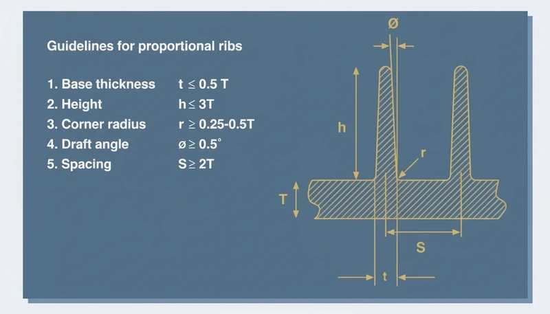
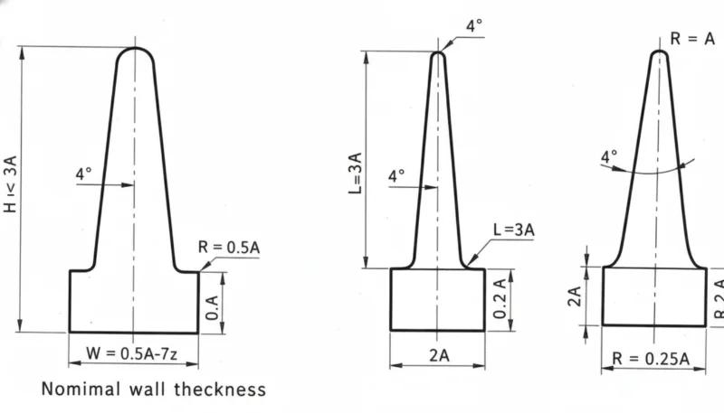
How Should Wall Thickness Be Designed for MUD Inserts?
Wall thickness is one of the most critical design variables in any injection-molded part, and MUD inserts have no special exemption from the fundamental rules. The governing principles are: maintain uniform wall thickness (variation under ±25% between adjacent walls), stay within the recommended range for the chosen material, and design transitions between thick and thin sections with gradual tapers (1:3 to 1:5 ratio) to prevent sink marks, voids, and warpage. For common engineering thermoplastics, the recommended wall thickness ranges are: ABS 1.5–3.5 mm, PP 1.0–3.5 mm, PC 1.5–4.0 mm, PA (nylon) 1.5–3.0 mm, and POM 1.5–3.0 mm.
In MUD inserts specifically, wall thickness uniformity is even more critical than in dedicated molds because the master frame’s cooling system is fixed and designed for average part geometry. If your insert has extreme wall thickness variations, the fixed cooling system may produce acceptable results in thin areas but unacceptable results in thick sections (or vice versa). This is where 3D-printed conformal cooling inserts offer a significant advantage: they can be tailored to your specific part geometry rather than relying on the frame’s generic cooling layout.
What Gate and Runner Considerations Apply to MUD Insert Design?
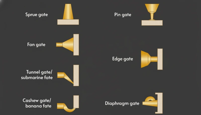
Gate placement in MUD inserts is constrained by the master frame’s runner system—a fixed channel network that routes molten plastic from the machine nozzle to the insert cavity. Most standard MUD frames use a center sprue gate or a side-gated sub-runner system. This means your part must be designed with a gate location compatible with where the frame delivers the runner. Common MUD gate types include: edge gates (simple, low cost, leaves a gate vestige), submarine (tunnel) gates (self-degating, no vestige trimming required), and fan gates (for wide, flat parts requiring even flow distribution).
The most common mistake we see in MUD insert design is the customer finalizing part geometry without considering gate location constraints of the intended master frame. When the gate position is forced into a structurally or aesthetically critical area (such as a visible A-surface or a highly stressed region), the resulting weld lines, gate mark, or flow-induced orientation become difficult to manage. The rule in our factory: determine the master frame and gate system before finalizing part design, not after.
What Are the Key Venting and Cooling Guidelines for MUD Inserts?
Venting in MUD inserts follows the same principles as full molds but with an additional constraint: vents must be positioned to work within the insert’s interface with the master frame. Vent depth is typically 0.025–0.05 mm for most amorphous resins and 0.01–0.03 mm for semi-crystalline resins that flash easily. Verabschiedung2 line vents (around the insert perimeter) are standard, supplemented by ejector pin clearance venting and, for deep features, venting cores or inserts. Inadequate venting in MUD inserts causes short shots, burn marks (diesel effect), and excessive fill pressure—problems that can mislead troubleshooters into adjusting process parameters when the real issue is trapped gas.
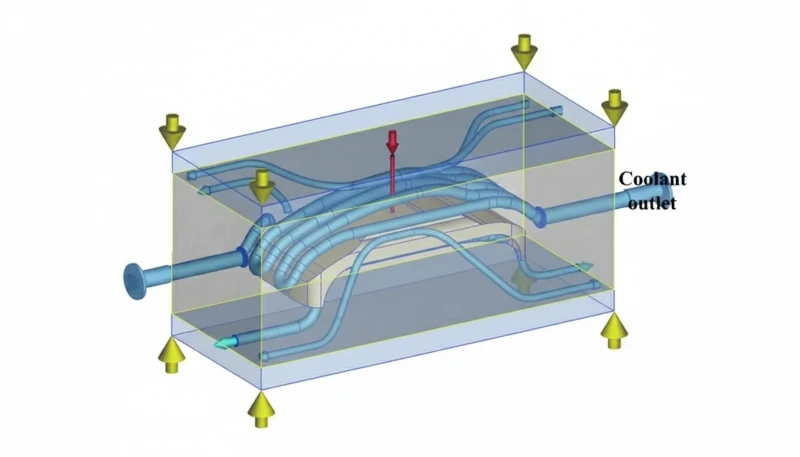
Cooling in MUD inserts is typically provided by the master frame’s cooling circuit, which routes water through channels in the frame body. The insert itself usually relies on conduction through the insert-to-frame interface for heat removal. For thermally demanding applications, dedicated Kühlkanäle3 can be drilled directly into the insert block, provided they don’t violate the structural integrity of the insert (minimum 3× channel diameter of steel wall thickness between channel and cavity). 3D-printed metal inserts with conformal channels have become an attractive option for thermally difficult parts where the standard frame cooling is insufficient.
“The master frame’s cooling system is always sufficient for any MUD insert cavity.”Falsch
The master frame’s cooling is a compromise designed for average part geometry. Parts with thick sections, poor thermal conductivity materials (e.g., PC, PEEK), or complex geometry often require dedicated insert cooling channels or conformal cooling to achieve acceptable cycle times and part quality.
“Adding dedicated cooling channels to a MUD insert significantly reduces cycle time for thermally demanding parts.”Wahr
MUD-Einsatz-Designrichtlinien: Entwurf, Wand & Anguss
What Ejection System Guidelines Apply to MUD Inserts?
MUD insert ejection systems must integrate with the master frame’s ejector plate and pin layout. Standard MUD frames use a fixed ejector plate with predetermined pin locations. When designing a MUD insert, the ejector pins must: be positioned over thick sections or rib bases (not thin walls that would deform under ejection force), avoid cosmetic A-surfaces where pin marks are unacceptable, and provide balanced ejection force distribution to prevent part tilting or sticking. For parts where the frame’s standard pin layout doesn’t match the optimal ejection strategy, the insert can be designed with internal ejector features—stripper plates, blade ejectors, or core-mounted pins—that work within the frame’s push system.
FAQ
What does MUD stand for in injection molding?
MUD stands for Master Unit Die. It refers to a modular tooling system where a standardized master frame accepts interchangeable cavity inserts. The “master unit” is the reusable frame; the “die” refers to the insert containing the part cavity. The system is also called modular tooling or unit tooling by some suppliers.
What materials are MUD inserts typically machined from?
Most MUD inserts are machined from aluminum alloys (typically 7075 or QC-10 for better hardness and wear resistance) for prototype and low-volume use, or P20 and H13 tool steel for higher-volume or abrasive material applications. Beryllium copper inserts are used in thermally demanding areas. 3D-printed metal (DMLS H13 or maraging steel) is increasingly used for conformal cooling applications.
Can MUD inserts handle engineering resins like PC and PEEK?
Yes, but material choice for the insert is critical. Aluminum inserts can handle PC (melt temp 280–320°C) for limited runs, but wear faster than steel at high processing temperatures. For PEEK (370–400°C) and other high-temperature engineering resins, hardened tool steel inserts (H13, S7) with dedicated cooling are required to maintain dimensional stability and surface finish.
How do I size my part for a standard MUD insert?
Start with the standard master frame sizes available in your factory or from your tooling supplier (DME, Hasco, Progressive Components have standard catalogs). The part must fit within the insert cavity area with adequate steel wall thickness on all sides (minimum 15–25 mm from cavity to insert edge). Account for the sintering shrinkage of the insert material and for any side-actions or lifters needed for undercut4s.
Can MUD inserts have side-actions for undercuts?
Yes, but with constraints. Side-actions (slides) must be designed to fit within the insert block and must actuate via cam pins or hydraulic cylinders that work with the master frame’s geometry. Small lifter inserts for internal undercuts can also be incorporated. The key limitation is available space within the insert block for the slide mechanism—MUD inserts have less space than dedicated full molds.
What is the minimum wall thickness between cooling channel and cavity?
The minimum wall thickness between a cooling channel and the cavity surface should be at least 3 times the channel diameter for aluminum inserts and 2.5 times for steel inserts. For a 6 mm (1/4″) cooling channel, this means at least 18 mm of aluminum (or 15 mm of steel) between channel and cavity—a constraint that limits how aggressively you can position cooling circuits in small inserts.
Zusammenfassung
Designing parts and tooling for MUD insert systems requires applying the same injection molding design fundamentals—draft angles, uniform wall thickness, proper gating, adequate venting, and balanced ejection—within the additional constraints of the master frame geometry. The reward for following these guidelines is substantial: 40–70% tooling cost reduction, 1–3 week lead time versus 4–8 weeks for full molds, and the flexibility to run multiple part variants on the same machine with minimal changeover time. In our factory, MUD systems have become the standard approach for any product development project requiring real injection-molded parts before committing to production tooling investment. The key to success is treating MUD design as a discipline, not a shortcut—the same engineering rigor that makes a great production mold makes a great MUD insert.
-
Cooling channels in injection molds are fluid passages (typically water at 20–60°C) machined or printed into the mold body to extract heat from the molten plastic. Channel diameter is typically 8–12 mm, positioned 10–20 mm from the cavity surface. Proper cooling channel design is the single largest factor controlling cycle time and part dimensional stability. ↩
-
Tiefgangswinkel: The slight taper applied to vertical walls of a mold feature to facilitate part ejection. MUD inserts typically require 1–3° minimum draft on most surfaces, with textured surfaces requiring 3–5°. ↩
-
Undercut: A recessed or protruding feature that prevents straight ejection from the mold. In MUD inserts, undercuts require side-actions, lifters, or collapsible cores, which significantly increase insert complexity and cost. ↩
-
Trennungslinie: The boundary line where the two halves of a mold meet. In MUD insert design, the parting line position determines which features require draft, where flash may occur, and how ejection is configured. ↩


