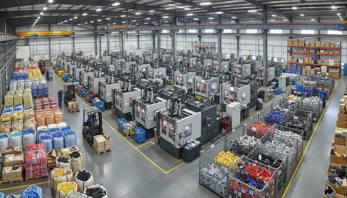
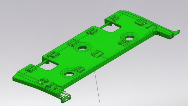
¿Qué es un sistema de insertos MUD y por qué es importante para el coste del utillaje?
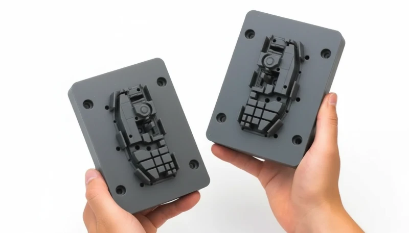
Un sistema de insertos MUD (Master Unit Die) consta de un bastidor maestro de molde estandarizado que admite insertos de cavidad intercambiables: bloques mecanizados que contienen la geometría específica de la pieza. En lugar de fabricar un molde completo para cada pieza nueva, los fabricantes invierten una sola vez en un bastidor maestro y fabrican únicamente el inserto de cavidad, menos costoso, para cada variante. En nuestra fábrica hemos creado una biblioteca de 12 bastidores maestros en tres tamaños estándar y cambiamos los insertos con regularidad para crear prototipos de piezas nuevas o ejecutar pequeños lotes de producción sin el plazo de entrega de 4–8 semanas que exige un molde específico completo.
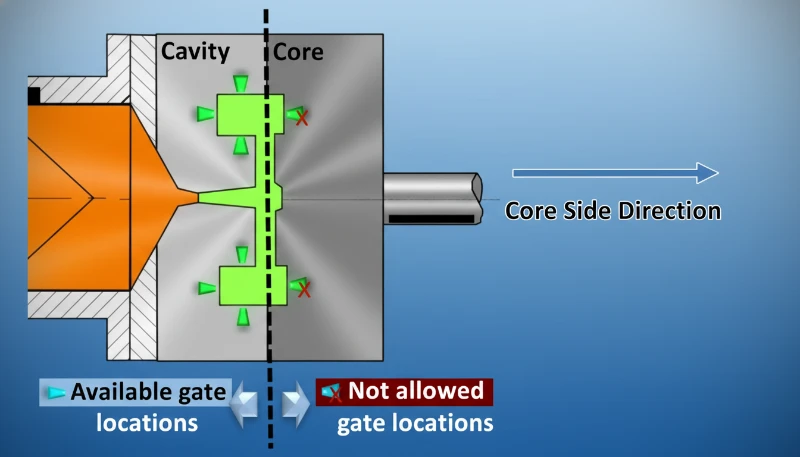
La justificación económica de MUD es mayor en el desarrollo de productos y la producción de volumen bajo a medio. Un molde de inyección completo dedicado puede costar $15,000–$80,000 y tardar 4–8 semanas en construirse. Un inserto MUD equivalente cuesta $2,000–$12,000 y puede mecanizarse en 1–3 semanas. Para productos que requieren varias iteraciones de diseño o variantes de pieza, el ahorro acumulado es considerable. Así se compara MUD con otros enfoques de utillaje:
| Tipo de utillaje | Coste típico | Plazos de entrega | Vida útil en ciclos | Mejor caso de uso |
|---|---|---|---|---|
| Inserto MUD (aluminio) | $2,000–$8,000 | 1–2 semanas | 10,000–50,000 | Prototipo, producción puente |
| Inserto MUD (acero) | $4,000–$15,000 | 2–3 semanas | 100,000–500,000 | Producción baja-media |
| Molde completo de aluminio | $5,000–$25,000 | 2–4 semanas | 10,000–100,000 | Producción de bajo volumen |
| Molde de producción íntegramente de acero | $15,000–$100,000+ | 4–8 semanas | 500,000+ | Producción de gran volumen |
¿Cuáles son las directrices críticas sobre el ángulo de desmoldeo para insertos MUD?
Los ángulos de desmoldeo son la ligera inclinación aplicada a las paredes verticales en la dirección del molde para permitir que la pieza se expulse limpiamente sin adherirse ni dejar marcas de arrastre. Para los insertos MUD, las directrices son: mínimo 1° para superficies lisas (pulidas), 1.5–2° para textura ligera (superficie SPI B1–B3), 3–5° para textura media (patrones EDM) y hasta 5–7° para grano profundo o superficies erosionadas por chispa. Un ángulo insuficiente es una de las causas más habituales de adherencia de la pieza, marcas de pasadores expulsores y arrastre superficial; problemas que en un molde completo dedicado podrían corregirse mediante pulido, pero que en un inserto MUD pueden requerir volver a mecanizar el propio inserto.
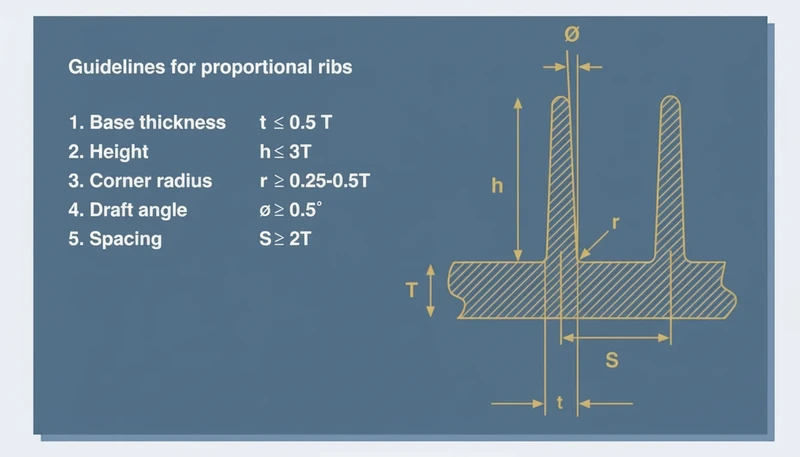
«Un ángulo de desmoldeo de 0,5° es suficiente para la mayoría de las piezas de plástico moldeadas por inyección en insertos MUD».False
Un ángulo de desmoldeo de 0,5° es insuficiente para la mayoría de las aplicaciones prácticas de insertos MIM. El mínimo recomendado es de 1° para superficies lisas pulidas y de 1,5–3° para cualquier superficie texturizada. Un ángulo inferior a 1° conlleva riesgo de adhesión de la pieza a la cavidad, lo que provoca marcas de arrastre en la superficie, marcas blancas de tensión o daños en el inserto durante la expulsión.
“Los requisitos del ángulo de desmoldeo aumentan con una mayor profundidad de embutición y una textura superficial más gruesa en los insertos MUD.”True
Por cada 0.025 mm (0.001 pulg.) de profundidad de textura, agregue aproximadamente 1.5° de ángulo de desmoldeo. Una textura de grano profundo de 0.1 mm requiere un mínimo de 6° de desmoldeo. Las características de estirado profundo (>50 mm de profundidad) también requieren un ángulo de desmoldeo adicional porque la fricción se acumula sobre un área de pared más grande, aumentando los requisitos de fuerza de expulsión.
¿Cómo debe diseñarse el espesor de pared de los insertos MUD?
El espesor de pared es una de las variables de diseño más críticas de cualquier pieza moldeada por inyección, y los insertos MUD no constituyen una excepción a las reglas fundamentales. Los principios rectores son: mantener un espesor de pared uniforme (variación inferior a ±25 % entre paredes adyacentes), mantenerse dentro del intervalo recomendado para el material elegido y diseñar las transiciones entre secciones gruesas y delgadas con conicidades graduales (relación de 1:3 a 1:5) para evitar rechupes, vacíos y deformaciones. Para los termoplásticos técnicos habituales, los intervalos de espesor de pared recomendados son: ABS 1,5–3,5 mm, PP 1,0–3,5 mm, PC 1,5–4,0 mm, PA (nailon) 1,5–3,0 mm y POM 1,5–3,0 mm.
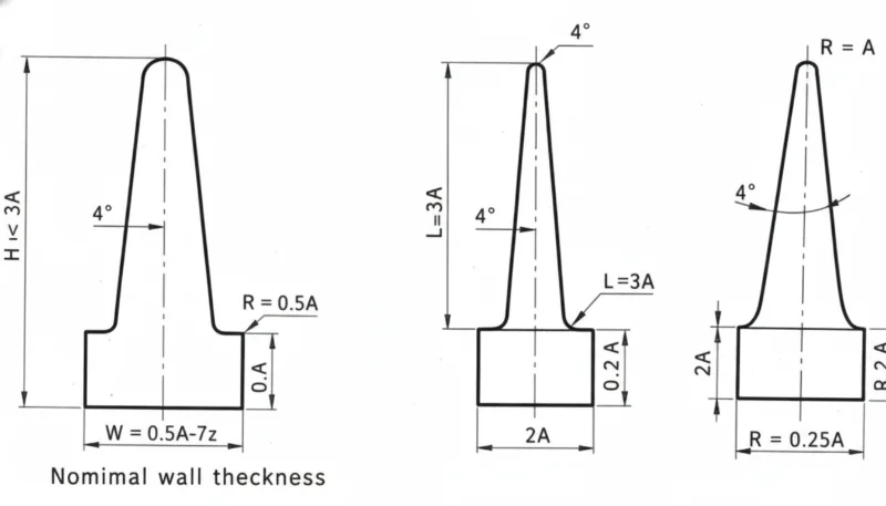
En los insertos MUD, la uniformidad del espesor de pared es aún más crítica que en los moldes específicos, porque el sistema de refrigeración del bastidor maestro es fijo y está diseñado para una geometría media de la pieza. Si el inserto presenta variaciones extremas del espesor de pared, el sistema fijo puede producir resultados aceptables en las zonas delgadas, pero inaceptables en las secciones gruesas, o viceversa. Aquí es donde los insertos de refrigeración conformal impresos en 3D ofrecen una ventaja considerable: pueden adaptarse a la geometría concreta de la pieza en lugar de depender de la disposición genérica de refrigeración del bastidor.
¿Qué consideraciones sobre compuertas y canales se aplican al diseño de insertos MUD?
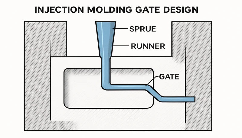
La ubicación del punto de inyección en los insertos MUD está limitada por el sistema de canales del bastidor maestro: una red fija de conductos que lleva el plástico fundido desde la boquilla de la máquina hasta la cavidad del inserto. La mayoría de los bastidores MUD estándar utilizan un bebedero central o un sistema de subcanal con punto de inyección lateral. Esto significa que la pieza debe diseñarse con una ubicación del punto de inyección compatible con el lugar donde el bastidor suministra el canal. Los tipos habituales de puntos de inyección MUD incluyen: puntos laterales (simples, económicos y dejan vestigio), puntos submarinos (túnel) (separación automática, sin necesidad de recortar el vestigio) y puntos en abanico (para piezas anchas y planas que requieren una distribución uniforme del flujo).
El error más habitual que observamos en el diseño de insertos MUD es que el cliente finaliza la geometría de la pieza sin considerar las restricciones de ubicación de la compuerta del bastidor maestro previsto. Cuando la posición de la compuerta queda forzada en una zona estructural o estéticamente crítica (como una superficie A visible o una región sometida a grandes esfuerzos), resulta difícil controlar las líneas de soldadura, la marca de la compuerta o la orientación inducida por el flujo. La regla de nuestra fábrica es determinar el bastidor maestro y el sistema de compuerta antes de finalizar el diseño de la pieza, no después.
¿Cuáles son las pautas clave de ventilación y enfriamiento para insertos MUD?
La ventilación de los insertos MUD sigue los mismos principios que la de los moldes completos, pero con una limitación adicional: los respiraderos deben colocarse de modo que funcionen dentro de la interfaz entre el inserto y el bastidor maestro. La profundidad de los respiraderos suele ser de 0,025–0,05 mm para la mayoría de las resinas amorfas y de 0,01–0,03 mm para las resinas semicristalinas que generan rebabas con facilidad. Los respiraderos de la línea de partición2 (alrededor del perímetro del inserto) son habituales y se complementan con la holgura de los pasadores expulsores y, en elementos profundos, con núcleos o insertos ventilados. Una ventilación insuficiente en los insertos MUD provoca llenados incompletos, marcas de quemado (efecto diésel) y una presión de llenado excesiva; estos problemas pueden llevar a ajustar los parámetros del proceso cuando la causa real es el gas atrapado.
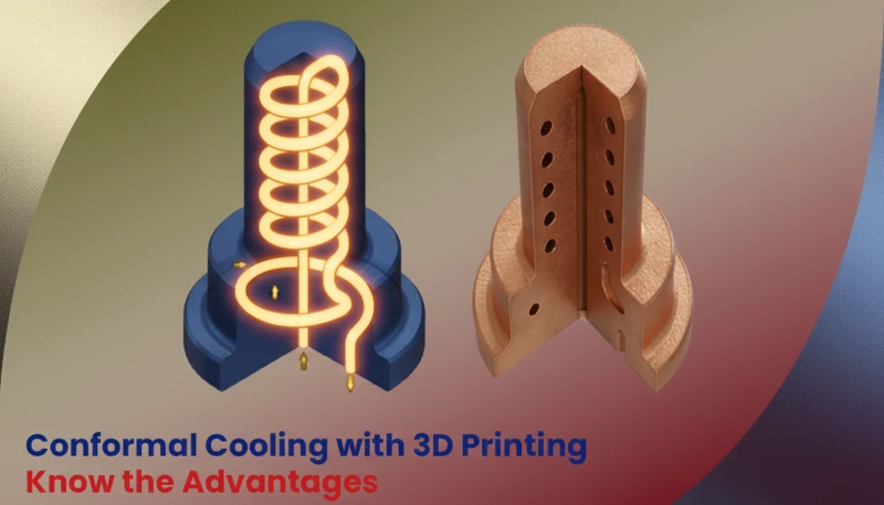
La refrigeración de los insertos MUD suele proceder del circuito de refrigeración del bastidor maestro, que hace circular agua por canales situados en el cuerpo del bastidor. El propio inserto suele disipar el calor por conducción a través de la interfaz entre inserto y bastidor. En aplicaciones con alta exigencia térmica, pueden perforarse canales de refrigeración3 específicos directamente en el bloque del inserto, siempre que no comprometan su integridad estructural (espesor mínimo de pared de acero entre el canal y la cavidad igual a 3 veces el diámetro del canal). Los insertos metálicos impresos en 3D con canales conformales se han convertido en una opción atractiva para piezas con dificultades térmicas cuando la refrigeración estándar del bastidor resulta insuficiente.
«El sistema de refrigeración del bastidor maestro siempre es suficiente para cualquier cavidad de inserto MUD».False
La refrigeración del bastidor maestro es un compromiso para una geometría media. Piezas gruesas, materiales de baja conductividad como PC o PEEK y geometrías complejas suelen requerir canales específicos en el inserto o refrigeración conformal para lograr ciclos y calidad aceptables.
“Añadir canales de refrigeración específicos a un inserto MUD reduce considerablemente el tiempo de ciclo de las piezas con altas exigencias térmicas.”True
Pautas de Diseño de Inserto MUD: Proyecto, Pared y Compuerta
¿Qué directrices del sistema de expulsión se aplican a los insertos MUD?
Los sistemas de expulsión de insertos MUD deben integrarse con la placa expulsora y la disposición de pasadores del bastidor maestro. Los bastidores MUD estándar utilizan una placa expulsora fija con ubicaciones de pasadores predeterminadas. Al diseñar un inserto MUD, los pasadores expulsores deben: colocarse sobre secciones gruesas o bases de nervaduras (no sobre paredes delgadas que se deformarían bajo la fuerza de expulsión), evitar las superficies estéticas de clase A donde las marcas de los pasadores son inaceptables y proporcionar una distribución equilibrada de la fuerza de expulsión para evitar que la pieza se incline o se atasque. Para las piezas en las que la disposición estándar de pasadores del bastidor no coincide con la estrategia de expulsión óptima, el inserto puede diseñarse con elementos expulsores internos—placas extractoras, expulsores de lámina o pasadores montados en el núcleo—que funcionan dentro del sistema de empuje del bastidor.
PREGUNTAS FRECUENTES
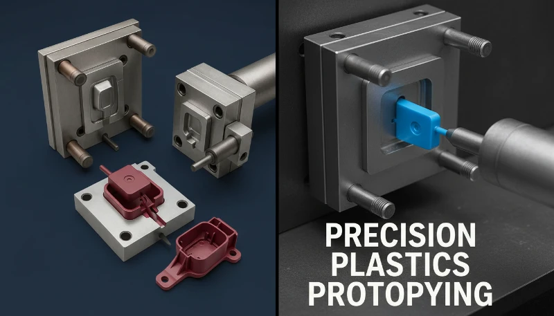
¿Qué significa MUD en el moldeo por inyección? MUD significa Master Unit Die. Se refiere a un sistema de utillaje modular en el que un bastidor maestro estandarizado admite insertos de cavidad intercambiables. La «unidad maestra» es el bastidor reutilizable, mientras que «matriz» alude al inserto que contiene la cavidad de la pieza. Algunos proveedores también denominan al sistema utillaje modular o utillaje unitario.
¿Con qué materiales suelen mecanizarse los insertos MUD? La mayoría de los insertos MUD se mecanizan en aleaciones de aluminio —normalmente 7075 o QC-10, por su mayor dureza y resistencia al desgaste— para prototipos y volúmenes bajos, o en aceros para herramientas P20 y H13 para volúmenes mayores o aplicaciones con materiales abrasivos. En las zonas con alta exigencia térmica se utilizan insertos de cobre-berilio. El metal impreso en 3D (H13 por DMLS o acero martensítico envejecible) se emplea cada vez más en aplicaciones de refrigeración conformal.
¿Pueden los insertos MUD procesar resinas técnicas como PC y PEEK? Sí, pero es fundamental elegir bien el material del inserto. Los insertos de aluminio pueden procesar PC (temperatura de fusión de 280–320 °C) en series limitadas, aunque se desgastan más rápido que los de acero a altas temperaturas de proceso. Para PEEK (370–400 °C) y otras resinas técnicas de alta temperatura, se requieren insertos de acero para herramientas endurecido (H13, S7) con refrigeración específica para mantener la estabilidad dimensional y el acabado superficial.
¿Cómo dimensiono mi pieza para un inserto MUD estándar? Empiece por los tamaños de bastidor maestro estándar disponibles en su fábrica o a través de su proveedor de utillaje (DME, Hasco y Progressive Components disponen de catálogos estándar). La pieza debe caber en el área de cavidad del inserto dejando un espesor de pared de acero suficiente en todos los lados (un mínimo de 15–25 mm desde la cavidad hasta el borde del inserto). Tenga en cuenta la contracción por sinterización del material del inserto y las correderas o los expulsores inclinados necesarios para los contrasalidas4.
¿Pueden los insertos MUD incorporar correderas para contrasalidas? Sí, pero con limitaciones. Las correderas deben caber dentro del bloque del inserto y accionarse mediante pasadores inclinados o cilindros hidráulicos compatibles con la geometría del bastidor maestro. También pueden incorporarse pequeños insertos elevadores para contrasalidas internas. La principal limitación es el espacio disponible dentro del bloque para el mecanismo de la corredera: los insertos MUD ofrecen menos espacio que los moldes completos específicos.
¿Cuál es el espesor mínimo de pared entre el canal de refrigeración y la cavidad? El espesor mínimo entre un canal de refrigeración y la superficie de la cavidad debe ser de al menos 3 veces el diámetro del canal en insertos de aluminio y 2,5 veces en insertos de acero. Para un canal de refrigeración de 6 mm (1/4″), esto supone al menos 18 mm de aluminio —o 15 mm de acero— entre el canal y la cavidad, una restricción que limita lo cerca que pueden situarse los circuitos de refrigeración en insertos pequeños.
Resumen
Diseñar piezas y utillajes para sistemas de insertos MUD exige aplicar los mismos fundamentos del diseño para moldeo por inyección —ángulos de desmoldeo, espesor de pared uniforme, entrada adecuada, ventilación suficiente y expulsión equilibrada— dentro de las limitaciones adicionales de la geometría del bastidor maestro. Seguir estas pautas ofrece ventajas considerables: una reducción del 40–70 % en el coste del utillaje, plazos de 1–3 semanas frente a las 4–8 semanas de los moldes completos y flexibilidad para producir varias variantes de una pieza en la misma máquina con un tiempo de cambio mínimo. En nuestra fábrica, los sistemas MUD se han convertido en la solución estándar para cualquier proyecto de desarrollo que requiera piezas reales moldeadas por inyección antes de invertir en utillaje de producción. La clave del éxito consiste en tratar el diseño MUD como una disciplina, no como un atajo: el mismo rigor de ingeniería que produce un excelente molde de producción produce un excelente inserto MUD. Consulte nuestra Guía completa del molde de inyección para obtener una visión general exhaustiva. Consulte nuestra Guía completa del molde de inyección para obtener una visión general exhaustiva.
-
Los canales de refrigeración de los moldes de inyección son conductos para fluidos —normalmente agua a 20–60 °C— mecanizados o impresos en el cuerpo del molde para extraer calor del plástico fundido. Su diámetro suele ser de 8–12 mm y se sitúan a 10–20 mm de la superficie de la cavidad. Un diseño correcto de los canales de refrigeración es el factor que más influye en el tiempo de ciclo y la estabilidad dimensional de la pieza. ↩
-
Ángulo de desmoldeo: La ligera inclinación aplicada a las paredes verticales de un elemento del molde para facilitar la expulsión de la pieza. Los insertos MUD suelen requerir un ángulo mínimo de 1–3° en la mayoría de las superficies y de 3–5° en las superficies texturizadas. ↩
-
Contrasalida: Elemento rebajado o saliente que impide expulsar la pieza en línea recta del molde. En los insertos MUD, las contrasalidas requieren correderas, expulsores inclinados o machos colapsables, lo que aumenta considerablemente la complejidad y el coste del inserto. ↩
-
Línea de partición: Línea límite donde se unen las dos mitades de un molde. En el diseño de insertos MUD, la posición de la línea de partición determina qué elementos necesitan ángulo de desmoldeo, dónde pueden aparecer rebabas y cómo se configura la expulsión. ↩
Obtenga precios competitivos, comentarios de DFM y un calendario de producción del equipo de ingeniería de ZetarMold.