 İçeriğe geç

Kapı tipleri
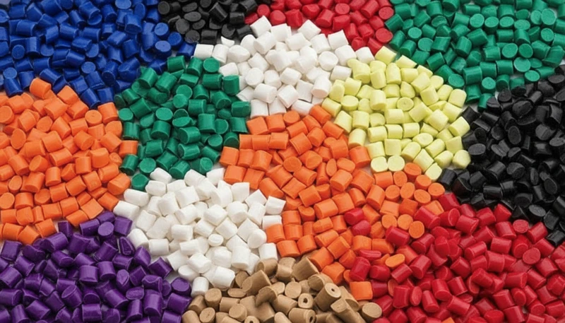
Enjeksiyon kalıplama1 with polyethylene (PE) is the most common thermoplastic processing method due to PE’s versatility and cost-effectiveness. This semi-crystalline polymer1 ranges from low-density (LDPE) to high-density (HDPE) variants, each offering distinct processing characteristics and end-use properties.
At ZetarMold’s Shanghai facility, established in 2005, we process PE grades daily across 45 injection molding machines ranging from 90T to 1850T. Our 20+ years of production experience with PE spans applications from simple caps and containers to complex automotive components. PE’s excellent chemical resistance, low moisture absorption (typically ≤0.01%), and good electrical insulation make it ideal for food packaging, consumer goods, and industrial applications.
“Mold cooling time is the largest portion of PE molding cycle time.”Doğru
PE has low thermal conductivity, requiring significant cooling time for crystallization. Optimizing cooling channel design reduces cycle time while maintaining part quality.
“Faster cooling always produces better PE parts.”Yanlış
Rapid cooling can cause incomplete crystallization, warping, and reduced mechanical properties. Controlled cooling rates optimize the balance between speed and quality.
PE injection molding requires precise control over melt temperature and cooling rates because of its crystalline nature. Proper processing ensures consistent part quality, dimensional stability, and optimal mechanical properties. We’ve found that understanding PE’s unique characteristics is essential for achieving high-quality parts with minimal defects.
The polymer chains in PE can crystallize significantly when cooled properly, which affects the final part’s stiffness, impact strength, and appearance. In our production environment, we’ve processed over 400 different PE materials, from standard commodity grades to specialty formulations for demanding applications. Each grade requires specific processing adjustments to achieve optimal results.
How Does PE Material Selection Affect Processing?
Material selection directly impacts processing parameters and final part performance in enjeksiyon kalıbı design. LDPE offers excellent flexibility and impact strength but requires lower processing temperatures (140-200°C). HDPE provides higher stiffness and temperature resistance, processing at 160-220°C with lower shrinkage rates.
“Higher melt temperature improves PE flow but increases cycle time.”Doğru
PE viscosity drops at higher temperatures, enabling better thin-section filling. However, excessive heat extends cooling and may cause degradation.
“Increasing melt temperature always improves part quality.”Yanlış
While higher temperature improves flow, it can cause splay from moisture, increase cycle time, and risk thermal degradation.
We’ve processed over 400 different PE materials at our Shanghai factory, including specialty grades like UHMWPE for wear-resistant applications. Each grade demands specific mold designs and processing adjustments. For example, UHMWPE requires higher temperatures and specialized screw designs due to its extremely high molecular weight and melt viscosity.
In our 20+ years of experience, we’ve seen that matching PE grade to application requirements prevents costly rework and ensures optimal part performance. Our 8 senior engineers analyze each project’s requirements and recommend the optimal PE variant based on mechanical property needs, environmental exposure, and cost considerations. We’ve learned from numerous production runs that the right material choice can make the difference between a successful project and repeated failures.
Our material selection process considers factors like melt flow rate (MFR)2, density, molecular weight distribution, and additive packages. These properties affect flow behavior, shrinkage, and final part properties. We’ve developed processing windows for each PE grade we regularly use, which helps us achieve consistent results across different production runs.
“Proper gate design is essential for consistent PE part quality.”Doğru
Gate size, location, and type directly affect fill pattern, packing efficiency, and weld line location. Optimized gate design reduces defects and improves dimensional consistency.
“Any gate type works equally well for PE molding.”Yanlış
Gate selection depends on part geometry, wall thickness, and production volume. Edge gates work for flat parts, while submarine gates suit cosmetic surfaces. Wrong gate type causes jetting or short shots.
The relationship between PE structure and processing behavior is fundamental to successful injection molding. Crystalline regions form during cooling, affecting stiffness and strength. Amorphous regions contribute to impact resistance. Understanding this balance helps our engineers design molds and processes that deliver optimal performance for each application.
Key Takeaways:
- PE requires minimal drying before processing
- Mold temperature affects crystallinity and shrinkage
- Processing varies by density and MFR rating
- Shrinkage rates range from 1.5% to 5.0%
What Are the Critical Processing Parameters for PE?
Successful PE injection molding depends on controlling several key processing parameters. Barrel temperature should be set 10°C above the melting point, typically 140-220°C depending on PE grade and melt flow rate. This ensures complete melting while preventing thermal degradation.
“PE shrinkage is anisotropic—higher in flow direction.”Doğru
Semi-crystalline PE orients during flow, shrinking more in the molecular orientation direction. Mold design must compensate.
“All PE grades have the same shrinkage rate.”Yanlış
Different PE grades have significantly different shrinkage rates. HDPE and LDPE shrink 1.5-3%, but molecular weight and additives affect actual rates.
Mold temperature plays a crucial role in crystallization. For LDPE, maintain 30-45°C; HDPE requires 40-60°C. Higher mold temperatures slow cooling, increase crystallinity, and improve mechanical properties while also increasing shrinkage. Our production team carefully balances these competing requirements based on part geometry and performance specifications.
Injection pressure for PE is relatively low due to its excellent flow characteristics. However, holding pressure and time are critical to minimize sink marks and ensure dimensional accuracy. We’ve found that optimal holding pressure is typically 60-80% of injection pressure, with holding time adjusted based on wall thickness and gate size.
Cooling time must be sufficient to allow proper crystallization before ejection. PE’s slow crystallization means cooling often represents 50-70% of total cycle time. Our mold designs incorporate efficient cooling systems to minimize cycle time while ensuring complete solidification. The cooling rate affects both crystallinity and internal stress, impacting final part properties.
“Proper gate design is essential for consistent PE part quality.”Doğru
Gate size, location, and type directly affect fill pattern, packing efficiency, and weld line location. Optimized gate design reduces defects and improves dimensional consistency.
“Any gate type works equally well for PE molding.”Yanlış
Gate selection depends on part geometry, wall thickness, and production volume. Edge gates work for flat parts, while submarine gates suit cosmetic surfaces. Wrong gate type causes jetting or short shots.
Injection speed affects molecular orientation and internal stress. Higher speeds increase orientation in the flow direction, which can enhance strength along that direction but reduce perpendicular properties. We optimize injection speed based on part geometry and performance requirements, using lower speeds for thick sections to minimize orientation effects.
Screw speed and back pressure also affect melt quality. PE generally requires moderate screw speeds (50-100 RPM) with minimal back pressure (50-100 bar) to prevent degradation and ensure uniform melting. Our equipment settings reflect years of experience optimizing these parameters for different PE grades and part configurations.

Why Is Shrinkage Management Critical in PE Molding?
LDPE daha düşük sıcaklıklarda (140-200°C) işlenir ve daha fazla büzülme gösterir. HDPE daha yüksek sıcaklıklar gerektirir (160-220°C) ve daha iyi boyutsal stabilite sağlar. Bu işleme farklılıkları, moleküler yapılarındaki ve kristalizasyon davranışlarındaki değişiklikleri yansıtır; bu faktörler, proses mühendislerimizin kalıp tasarımı ve işleme parametreleri seçiminde dikkate aldığı unsurlardır. HDPE 2.5-5.0%3. This substantial shrinkage requires careful compensation in tooling design and process optimization.
“Moisture causes splay in PE when processing regrind.”Doğru
While virgin PE has low moisture absorption, regrind can contain water. Drying at 60-80°C for 2-4 hours prevents splay.
“PE never requires drying before processing.”Yanlış
Virgin PE has low moisture sensitivity, but regrind and contamination require drying to prevent surface defects.
Anisotropic shrinkage causes warpage when cooling is uneven across different part sections. Our mold design team incorporates uniform cooling channels and appropriate gate locations to minimize directional shrinkage. We’ve seen proper cooling design reduce warpage by over 60% in complex geometries. The key is understanding how PE’s crystallization behavior interacts with part geometry and cooling conditions.
At ZetarMold, we account for shrinkage in tooling design based on the specific PE grade and part geometry. Our 8 senior engineers use DFM analysis to predict shrinkage behavior and adjust mold dimensions accordingly. We’ve developed comprehensive shrinkage data for various PE grades, which helps us design molds that produce parts within tight tolerances on the first run.
Crystallinity4 significantly affects shrinkage magnitude. Higher crystallinity increases shrinkage because more material contracts during the crystallization process. This relationship between mold temperature, crystallinity, and shrinkage creates a complex optimization problem. Higher mold temperatures increase crystallinity and improve mechanical properties but also increase shrinkage. We balance these competing factors based on application requirements.
“Proper gate design is essential for consistent PE part quality.”Doğru
Gate size, location, and type directly affect fill pattern, packing efficiency, and weld line location. Optimized gate design reduces defects and improves dimensional consistency.
“Any gate type works equally well for PE molding.”Yanlış
Gate selection depends on part geometry, wall thickness, and production volume. Edge gates work for flat parts, while submarine gates suit cosmetic surfaces. Wrong gate type causes jetting or short shots.
Wall thickness variations within a part cause differential shrinkage rates, leading to warpage and sink marks. Our design guidelines recommend maintaining uniform wall thickness whenever possible. When thickness variations are unavoidable, we implement gradual transitions and optimize gate locations to minimize stress concentrations and differential cooling effects.
Gate location and design influence shrinkage patterns. Parts filled through multiple gates often exhibit different shrinkage behavior compared to single-gate designs. We select gate locations that promote uniform filling and minimize flow length differences, which helps achieve more consistent shrinkage throughout the part.
What Common Defects Occur in PE Injection Molding?
Sink marks often appear near thick sections or ribs due to uneven cooling and material shrinkage. Our production team addresses this by optimizing gate location, reducing wall thickness variations, and extending cooling time. We’ve found that proper rib design—typically 50-60% of wall thickness—helps minimize sink marks while maintaining structural integrity.
“Mold temperature affects PE crystallinity and final properties.”Doğru
Higher mold temperatures promote more complete crystallization, increasing stiffness and dimensional stability.
“Lowering mold temperature always reduces cycle time without affecting quality.”Yanlış
While lower temperature reduces cooling time, it may cause incomplete crystallization, warping, and reduced stiffness.
Warpage results from differential shrinkage across the part. We’ve found that uniform mold temperature distribution and balanced cooling circuits are essential. Our DFM process analyzes potential warpage risks before tooling begins. We use mold flow simulation to predict warpage and adjust cooling channel placement accordingly. Many warpage issues can be resolved by modifying cooling system design rather than changing part geometry.
Flash occurs when injection pressure exceeds clamp force or mold sealing. At our facility, we maintain precise control over these parameters. Our 45 machines include 90T to 1850T clamping forces to match various part sizes. We also ensure proper mold maintenance to prevent wear that can create flash gaps. The relationship between clamp force, cavity pressure, and part area determines whether flash occurs, and we calculate these parameters for each production setup.
“Proper gate design is essential for consistent PE part quality.”Doğru
Gate size, location, and type directly affect fill pattern, packing efficiency, and weld line location. Optimized gate design reduces defects and improves dimensional consistency.
“Any gate type works equally well for PE molding.”Yanlış
Gate selection depends on part geometry, wall thickness, and production volume. Edge gates work for flat parts, while submarine gates suit cosmetic surfaces. Wrong gate type causes jetting or short shots.
Voids and bubbles form when trapped air cannot escape during filling or when material shrinks internally during cooling. Proper venting is critical, especially in deep cavities and thick sections. Our mold designs include strategically placed vents that allow air escape while preventing material flash. We also use multi-stage filling profiles that give trapped air time to escape before final pack and hold.
Splay or silver streaks appear when moisture or volatiles vaporize at the melt front. While PE has low moisture content, contamination or degradation can still cause splay. We prevent this through proper material handling, clean processing conditions, and appropriate temperature profiles. When splay occurs, we investigate potential sources of moisture, contamination, or excessive shear heating.
How Can You Optimize PE Mold Design?
Proper gate design is essential for PE parts. Large, rounded gates minimize flow hesitation and orientation effects. We typically use edge gates for flat parts and submarine gates for cylindrical components. Gate size depends on wall thickness and part volume—we generally use gates 50-70% of wall thickness for PE. Gate location affects filling patterns and weld line placement, which we optimize for structural and aesthetic requirements.
Ventilation must be adequate to allow trapped air to escape during filling. PE’s low viscosity can trap air in complex geometries. Our mold design incorporates strategic vent locations based on 20+ years of production experience. Vent depth is typically 0.015-0.025 mm, which allows air escape while preventing material flash. We place vents at end-of-fill locations and around blind holes where air accumulation occurs.
Cooling system design significantly impacts cycle time and part quality. PE’s slow crystallization requires sufficient cooling. Our tooling features conformal cooling channels where possible to optimize heat transfer and reduce cycle times. We use mold temperature simulation to optimize cooling channel placement and ensure uniform cooling throughout the cavity. Proper cooling reduces cycle time by up to 30% while improving part consistency.
“Proper gate design is essential for consistent PE part quality.”Doğru
Gate size, location, and type directly affect fill pattern, packing efficiency, and weld line location. Optimized gate design reduces defects and improves dimensional consistency.
“Any gate type works equally well for PE molding.”Yanlış
Gate selection depends on part geometry, wall thickness, and production volume. Edge gates work for flat parts, while submarine gates suit cosmetic surfaces. Wrong gate type causes jetting or short shots.
Surface finish considerations affect release characteristics and part appearance. PE tends to stick to highly polished surfaces. We use appropriate mold surface finishes—typically SPI #2 to #3 for most applications—to facilitate easy ejection while maintaining desired part appearance. Textured surfaces can improve release and hide minor surface imperfections.
Ejection system design must account for PE’s relatively low modulus and tendency toward deformation. We use generous ejection clearances and multiple ejection points to distribute forces evenly. Stripper plates are often preferable to pins for PE parts, especially those with thin walls. Our ejection designs minimize part distortion and ensure consistent cycle times.
Runner design affects material utilization and cycle efficiency. Cold runner systems are common for PE, though hot runner systems can reduce material waste for high-volume production. We optimize runner diameter and length to balance pressure drop, material heating, and cycle time. For multi-cavity molds, we use balanced runner designs to ensure uniform filling across all cavities.
What Temperature Profile Works Best for PE?
Temperature profile varies by PE grade and part design. For LDPE, use a gradient from 140°C (rear) to 200°C (front). HDPE requires higher temperatures: 160°C to 220°C. The rear zone should be cooler to prevent premature melting and ensure consistent feed, while front zones provide sufficient heat for complete melting and proper viscosity.
Nozzle temperature should match or slightly exceed the front zone temperature to prevent premature freezing. We’ve found that keeping nozzle temperatures 5-10°C above front zone ensures smooth flow and reduces gate blush. Nozzle temperature also affects the knit line strength at the gate, so we optimize this based on part requirements.
Melt temperature affects molecular orientation and residual stress. Higher temperatures reduce orientation but may degrade the polymer if excessive. Our process engineers optimize temperature balance for each application. We use pyrometers and melt temperature sensors to verify actual melt temperature, as barrel temperature settings don’t always reflect true melt conditions.
Temperature uniformity across the barrel is critical for consistent quality. Temperature fluctuations can cause viscosity variations leading to part defects. Our machines feature precise barrel temperature control with multiple heating zones to maintain optimal conditions throughout the melt. We’ve developed standard temperature profiles for each PE grade we process, which provides consistent starting points for new projects.
“Proper gate design is essential for consistent PE part quality.”Doğru
Gate size, location, and type directly affect fill pattern, packing efficiency, and weld line location. Optimized gate design reduces defects and improves dimensional consistency.
“Any gate type works equally well for PE molding.”Yanlış
Gate selection depends on part geometry, wall thickness, and production volume. Edge gates work for flat parts, while submarine gates suit cosmetic surfaces. Wrong gate type causes jetting or short shots.
Material residence time in the barrel affects thermal history and potential degradation. PE is relatively stable, but excessive residence time at high temperatures can cause yellowing and property degradation. We optimize shot size and cycle time to maintain appropriate residence times, typically 2-5 minutes for most applications. Our production monitoring systems track residence time and alert operators to potential issues.
The relationship between temperature and cycle efficiency requires careful optimization. Higher temperatures reduce viscosity and allow faster filling, but increase cooling time due to higher heat content. We balance these effects to minimize overall cycle time while maintaining part quality. Our process optimization considers temperature, pressure, and cooling time as an integrated system rather than isolated parameters.
When Should You Choose PE Over Other Materials?
PE excels in applications requiring chemical resistance, low cost, and good toughness. It’s ideal for containers, caps, toys, and automotive interior components. We’ve produced millions of PE parts across these industries. PE’s balance of properties and processability makes it the default material choice for many applications, with other materials selected only when specific requirements exceed PE’s capabilities.
Consider HDPE for applications requiring higher stiffness and temperature resistance. LDPE is better for flexibility and impact resistance. Our 30+ English-speaking project managers can help select the optimal PE grade. The choice between HDPE and LDPE depends on the balance of stiffness, impact resistance, temperature requirements, and cost for each specific application.
At ZetarMold, we manufacture 100+ sets of molds monthly, many for PE applications. Our in-house mold manufacturing capability ensures rapid turnaround and precise dimensional control for your PE projects. This vertical integration—from mold design and manufacture through production and quality control—provides our customers with exceptional quality and responsiveness.
“Proper gate design is essential for consistent PE part quality.”Doğru
Gate size, location, and type directly affect fill pattern, packing efficiency, and weld line location. Optimized gate design reduces defects and improves dimensional consistency.
“Any gate type works equally well for PE molding.”Yanlış
Gate selection depends on part geometry, wall thickness, and production volume. Edge gates work for flat parts, while submarine gates suit cosmetic surfaces. Wrong gate type causes jetting or short shots.
PE compares favorably to alternatives like PP, PVC, and PS in many applications. PE offers better impact strength than PP, lower density than PVC, and superior low-temperature performance compared to PS. Our material selection process considers these trade-offs along with cost and processing considerations to recommend the optimal material for each application.
Regulatory compliance is an important consideration for many PE applications. Food contact, medical device, and automotive applications require specific PE grades with appropriate regulatory approvals. We maintain inventory of FDA-approved, USP Class VI, and automotive-qualified PE materials to support regulated applications. Our documentation system ensures traceability and compliance documentation for these critical applications.
Environmental considerations increasingly influence material selection. PE is recyclable and can incorporate recycled content in many applications. Our facility supports sustainability initiatives through efficient processing practices and recycled material usage where appropriate. We help customers balance environmental objectives with performance and cost requirements in material selection decisions.
FAQ: PE Injection Molding
İşlemeden önce PE için ideal nem içeriği nedir?
PE typically contains ≤0.01% moisture and rarely requires drying. Only dry if the material has been exposed to high humidity for extended periods. In our Shanghai factory, we rarely pre-dry PE unless specific surface quality requirements dictate it. The material’s low moisture absorption makes it one of the easiest plastics to process from a moisture management perspective.
PE parçalar için doğru soğutma süresini nasıl belirlersiniz?
Cooling time depends on wall thickness, mold temperature, and PE grade. A general rule is 10-15 seconds per millimeter of wall thickness, adjusted for part geometry and mold temperature. Our process engineers use mold flow simulation and empirical data to optimize cooling time for each part design, balancing cycle time and part quality.
PE enjeksiyon kalıplı parçalarda çökme izlerine ne sebep olur?
Sink marks occur when thick sections cool and shrink more than adjacent thin sections. Proper gate placement, rib design, and cooling optimization prevent this issue. We’ve found that maintaining rib thickness at 50-60% of wall thickness and using adequate gate dimensions significantly reduces sink mark problems in PE parts.
PE yeniden işlenip tekrar kullanılabilir mi?
Yes, PE can be reground and reprocessed multiple times, though properties may gradually degrade. Many facilities use regrind at 10-30% with virgin material. Our production operations incorporate regrind wherever possible to reduce material costs and support sustainability objectives, though we maintain careful control over regrind quality and mixing ratios.
LDPE ve HDPE işleme arasındaki fark nedir?
LDPE processes at lower temperatures (140-200°C) and has higher shrinkage. HDPE requires higher temperatures (160-220°C) and has better dimensional stability. The processing differences reflect their different molecular structures and crystallization behaviors, which our process engineers account for in mold design and processing parameter selection.
PE parçalarında eğrilmeyi nasıl önlersiniz?
PE Enjeksiyon Kalıplama İşleme Kılavuzu Mühendisler İçin
PE enjeksiyon kalıplama için hangi güvenlik önlemleri geçerlidir?
PE is generally safe to process, but proper ventilation is recommended as degradation can produce odors. Maintain temperatures below 300°C to prevent thermal degradation. Our Shanghai facility maintains appropriate ventilation systems and process monitoring to ensure safe operating conditions throughout PE production runs.
-
Semi-crystalline polymers like PE have ordered molecular regions (crystallites) embedded in amorphous matrix, which governs their distinct shrinkage and mechanical behavior during cooling. ↩
-
Melt Flow Rate (MFR) measures how many grams of polymer flow through a standard die in 10 minutes under specified temperature and load, per ASTM D1238. Higher MFR indicates easier flow and better mold fill. ↩
-
Shrinkage data sourced from material datasheets: LDPE 1.5–3.0%, MDPE 2.0–4.0%, HDPE 2.5–5.0% (measured per ASTM D955). Actual values depend on wall thickness, gate design, and processing conditions. ↩
-
Higher mold temperature increases crystallinity in PE parts, which raises stiffness and heat deflection temperature but also increases post-mold shrinkage. The trade-off must be balanced per application requirements. ↩
Need a Quote for Your Injection Molding Project?
Get competitive pricing, DFM feedback, and production timeline from ZetarMold’s engineering team.
Request a Free Quote → See our Injection Molding Complete Guide for a comprehensive overview.


