 İçeriğe geç

- Conformal cooling reduces cycle time 15–30% compared to straight-drilled channels
- Baffles and bubblers improve heat transfer in thick sections
- Cooling system design affects part quality, cycle time, and mold cost
- Bimetallic molds use copper alloys for high-heat materials
- Simulation software helps optimize cooling channel placement before steel cutting
What Are Injection Mold Cooling Systems?
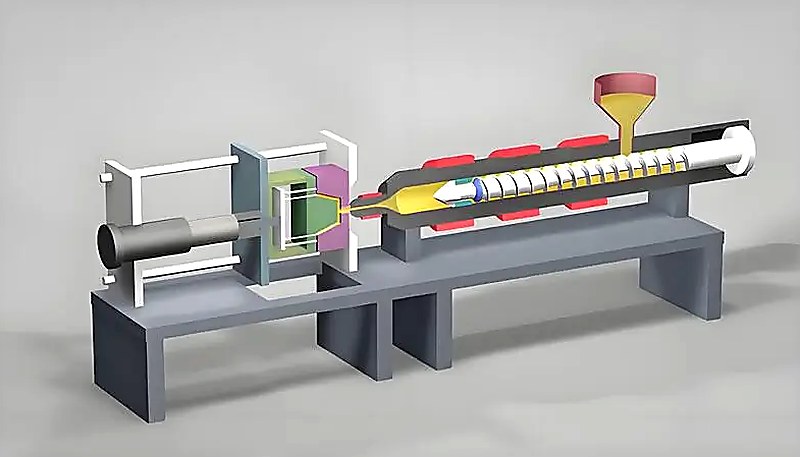
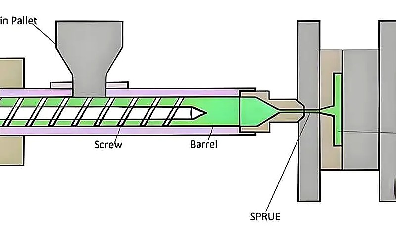
Injection mold cooling systems are heat removal systems that circulate coolant through channels in the mold to solidify molten plastic. In our experience at the Shanghai facility, we optimize cooling systems daily for 400+ material grades to balance cycle time with part quality. Proper cooling directly impacts injection molding cycle time, part dimensional stability, and production efficiency. Every injection molding operation balances three competing factors: mold material (steel type), part geometry, and cooling capacity.
The basic principle involves circulating coolant—typically water—through machined channels in the mold. Heat transfer efficiency determines how quickly a part reaches ejection temperature. Faster cooling enables shorter cycles and higher throughput, but aggressive cooling can cause warpage or sink marks in thick sections.
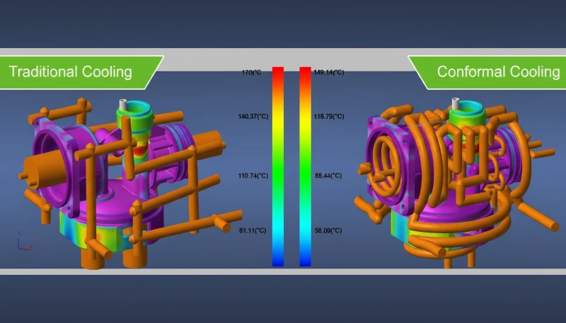
“Conformal cooling reduces cycle time 15–30% compared to straight-drilled channels by following the part geometry with curved cooling channels that maintain consistent distance from the mold surface.”Doğru
The consistent cooling distance allows faster, more uniform solidification of the plastic, reducing overall cycle time. This 15-30% improvement is significant for high-volume production.
“Straight-drilled cooling channels are always better than conformal cooling.”Yanlış
In reality, straight channels cost less and work well for simple geometries, but conformal cooling delivers superior cycle time reduction for high-volume production of complex parts. The choice depends on production volume and part complexity.
Manufacturers choose cooling system complexity based on annual part volume. High-volume production (millions of parts per year) justifies conformal cooling with hundreds of channels. Prototype or low-volume molds (under 50,000 parts) may use simple straight-drilled channels. The decision affects the enjeksiyon kalıbı1 tooling lifecycle cost upfront but saves money over the product lifecycle through faster cycles.
Cooling channel layout directly determines mold surface temperature distribution. In production molds, engineers use thermal simulation software to map temperature gradients across the cavity surface before committing to a channel layout. These simulations reveal hot spots—areas where the distance between the mold surface and the nearest cooling channel exceeds the optimal 3–5 mm threshold. Left unaddressed, hot spots cause differential shrinkage, longer cycle times, and dimensional inconsistency across production runs.
The Reynolds number of coolant flow inside channels determines whether heat transfer occurs through forced convection or natural convection. For effective cooling, designers target turbulent flow (Reynolds number above 4000) to maximize the convective heat transfer coefficient. Laminar flow creates an insulating boundary layer that reduces heat removal efficiency by up to 50%, which means that simply increasing coolant pressure without achieving turbulent flow provides diminishing returns for cooling performance.
What Is Traditional Straight-Drilled Cooling?
Traditional straight-drilled cooling are uniform-diameter channels drilled into mold plates using standard drill machines. Drill machines create perpendicular or parallel channels following simple geometric patterns. This approach costs less and works well for boxy parts with even wall thickness.
Straight-drilled channels work best when part walls are uniform and cooling distance remains consistent across the mold surface. Designers calculate cooling distance—the maximum distance from any part surface to the nearest cooling channel—to ensure uniform solidification. Straight channels typically maintain 2–4 mm spacing for standard engineering thermoplastics such as ABS, PP, and HDPE.
For simple geometries like flat plates or rectangular boxes, straight-drilled cooling provides adequate performance at minimal cost. Most prototype molds and low-volume production tools use this approach because the machining cost is predictable and the channels are easy to modify if needed. However, as part complexity increases with ribs, bosses, and varying wall thickness, straight channels struggle to maintain consistent cooling distance from all surfaces. This limitation becomes critical for precision parts requiring dimensional tolerances below 0.1 mm.
How Do Conformal Cooling Systems Work?
Conformal cooling systems work by following part geometry with curved cooling channels that maintain 3–5 mm spacing. These channels maintain a consistent distance from part surfaces throughout the mold, especially in corners, ribs, and complex features. CNC machining or additive manufacturing creates these curved paths.
Conformal cooling delivers ROI in high-volume production. A part running 2 million shots annually with a 45-second cycle saves approximately 375 hours compared to a 60-second traditional cooling cycle. That extra capacity reduces per-part cost despite the higher upfront tooling investment. When evaluating cooling system ROI2, most conformal cooling projects pay back within 12–18 months for volume production.
“Amorphous plastics like ABS and PC tolerate less aggressive cooling and solidify gradually, making them more forgiving of traditional straight-drilled cooling designs.”Doğru
Amorphous materials shrink evenly and are less sensitive to cooling rate variations compared to semi-crystalline materials. They can work well with standard channel spacing of 3-4 diameters.
“Cooling system design doesn’t affect part warpage.”Yanlış
In reality, uneven cooling is one of the primary causes of warpage in injection molding, especially for semi-crystalline materials like PP and nylon. Conformal cooling helps balance differential shrinkage.
What Are the Core Cooling Channel Design Principles?
Core cooling channel design principles are spacing 3–5 diameters apart, using 8–12 mm diameters, and targeting 1–3 m/s flow rate. Effective cooling system design follows core principles regardless of channel type. Uniform spacing ensures even heat extraction across all mold surfaces. Channels placed too far from thick sections create hot spots that extend cycle time or cause dimensional issues.
Standard channels use 8–12 mm diameters for most applications. Smaller diameters increase coolant velocity but raise pressure drop through the system. Larger diameters reduce flow velocity but allow more channels. Flow rate typically targets 1–3 m/s in cooling channels to maximize heat transfer coefficient between the coolant and mold steel surface. Turbulent flow at these velocities ensures efficient convective heat transfer and prevents stagnant boundary layers from insulating the mold surface from the coolant stream.
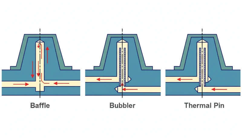
Baffles redirect coolant flow to reach areas deep in mold cores. Bubblers spray coolant directly into blind holes where straight channels cannot reach. These components improve cooling in tall, deep cores where part quality depends on core temperature control. In our experience, proper baffle placement in deep cores reduces cycle time by 10-15% for tall cylindrical parts such as battery cases and container molds.
Serial vs Parallel Cooling Connections
The water manifold distributes coolant from a single inlet to multiple mold zones. Serial connection (one channel into the next) causes uneven cooling—zones farther from the inlet receive warmer coolant. Parallel connection ensures each zone receives coolant at the same temperature, which is critical for multi-cavity molds producing parts with consistent dimensions across all cavities.
How Do Different Materials Affect Cooling Requirements?
Different materials affect cooling by requiring 10–60% different cooling times based on molecular structure. Amorphous plastics (ABS, PC, PS) solidify gradually and shrink evenly. They tolerate slightly less aggressive cooling but still require uniform temperature to minimize internal stresses. These materials work well with standard channel spacing (3–4 diameters).
Semi-crystalline materials (PP, PE, POM) crystallize during cooling and shrink more. They benefit from conformal cooling in complex geometries to control directional shrinkage. Mold surface temperature affects crystallinity and final part stiffness. Understanding these crystallinity effects3 is essential for selecting the right cooling approach. In our production of millions of PA6 and PA66 parts annually, we have observed that semi-crystalline materials require 20-30% longer cooling times than amorphous plastics like ABS to achieve optimal mechanical properties.
Material-Specific Cooling Times
Cooling time varies significantly based on material type and wall thickness. Semi-crystalline materials like nylon require 20–30% longer cooling than amorphous plastics like ABS, and thicker walls exponentially increase cooling duration due to slower internal heat conduction.
Crystalline Material Cooling Requirements
Crystalline materials (PA6, PA66, PEEK) require precise mold temperature control. These materials shrink significantly as crystals form. Conformal cooling combined with mold surface temperature variation (hot and cold zones) manages shrinkage and reduces warpage. Cooling efficiency directly affects mechanical properties—faster cooling produces smaller, more uniform crystals and higher tensile strength.
High-performance engineering resins such as PPS, PEEK, and LCP demand mold temperatures of 120–200 °C. These elevated temperatures require oil-based cooling circuits instead of water, adding system complexity and energy cost. The thermal mass of the mold steel also plays a role—heavier molds take longer to reach thermal equilibrium but maintain more stable temperatures during cycling, which reduces part-to-part variation in critical dimensions.
Glass-filled materials present additional cooling challenges. The glass fibers restrict polymer chain movement during crystallization, creating internal stresses that cause warpage if cooling is uneven. For 30% glass-filled nylon (PA6-GF30), mold temperature must be precisely controlled within ±2 °C to achieve consistent mechanical properties across the production run. This level of temperature control requires multiple independent cooling zones with individual thermolator connections.
What Are Common Cooling System Defects and Solutions?
Common cooling system defects are sink marks, warpage, and cycle time fluctuations caused by poor cooling design. Poor cooling causes several common injection molding defects: Sink marks occur in thick sections where the interior cools slower than the surface. Material shrinks inward as it solidifies. Solutions include adding cooling channels near thick sections, using baffles in deep cores, or conformal channels following the contour.
Warpage and Uneven Cooling
Warpage occurs when different part sections cool at uneven rates—one side solidifies and contracts before the other. Solutions include conformal cooling, adjusted channel placement, or modified gate locations to balance flow patterns.
Cooling System Maintenance and Stability
Cycle time fluctuations indicate cooling instability from inconsistent coolant temperature, fouled channels, or flow variations. Regular descaling and temperature checks maintain predictable cycles.
Hot molds cause flash; cold molds prevent cavity fill. Proper cooling balances fill and cycle time.
Thermal imaging cameras provide real-time feedback during mold trials. By capturing infrared images of the mold surface during cycling, engineers identify hot spots invisible to surface temperature probes. These thermal maps guide cooling channel adjustments before full production begins. A typical thermal analysis captures images at 10-cycle intervals to confirm temperature stabilization, which ensures the cooling system reaches thermal equilibrium before the production qualification run begins.
Thermal imaging cameras provide real-time feedback during mold trials. By capturing infrared images of the mold surface during cycling, engineers identify hot spots invisible to surface temperature probes. These thermal maps guide cooling channel adjustments before full production begins. A typical thermal analysis captures images at 10-cycle intervals to confirm temperature stabilization. Documenting thermal profiles creates a reference baseline for future maintenance—when cycle times drift, comparing current thermal images against the baseline reveals whether fouled channels or degraded seals are the root cause.
When Should You Use Bimetallic and Conformal Inserts?
Bimetallic and conformal inserts are used in high-heat areas, hot runner manifolds, and for materials requiring precise temperature control. Bimetallic molds combine a standard steel structure with copper or copper-alloy inserts in high-heat areas. Copper thermal conductivity (approximately 385 W/m·K) exceeds P20 steel (29–33 W/m·K) by more than 10 times. This dramatic conductivity difference allows copper inserts to extract heat from localized hot zones far more efficiently than steel alone.
Use bimetallic inserts for hot runner manifolds with high heat load, small difficult-to-cool core pins, areas where conformal channels in steel are impractical, and molds running high-temperature materials (PEEK, LCP). Bimetallic construction adds cost but dramatically reduces cycle time in localized hot zones.
How to Calculate Bimetallic Insert ROI
Manufacturers calculate ROI by comparing cycle time reduction against insert cost. A 5-second cycle improvement on a 2 million shot annual run saves approximately 2,778 hours of machine time per year of production. In our Shanghai facility, we have implemented bimetallic cooling solutions across dozens of high-volume production molds, consistently achieving 10-20% cycle time reductions in the hottest mold zones.
Conformal inserts manufactured through direct metal laser sintering (DMLS) offer another path to improved cooling in specific mold zones. These 3D-printed inserts create cooling channels that follow complex part geometries impossible to achieve with conventional drilling. While DMLS inserts cost 3–5 times more than machined copper alloys, they deliver superior cooling performance in deep rib areas and contoured surfaces where traditional methods cannot reach.
The decision between bimetallic copper inserts and conformal 3D-printed inserts depends on part geometry complexity and production volume. Copper inserts excel in flat or gently curved surfaces with high heat flux. DMLS conformal inserts justify their cost in molds with deep draws, tight radii, or variable wall thickness sections where cooling distance varies dramatically across the cavity surface.
Frequently Asked Questions About Cooling Systems
What is the ideal cooling time for injection molding?
Ideal cooling time depends on part thickness, material, and mold design. For 2 mm wall thickness in ABS, cooling typically takes 15–20 seconds. Thicker sections or materials with high crystallinity require 30–60 seconds. Simulation software predicts cooling time based on part geometry and cooling channel layout.
How do I know if my mold needs conformal cooling?
Evaluate annual volume and part complexity. High-volume production (500,000+ shots per year) with complex geometries benefits from conformal cooling. Calculate ROI by comparing cycle time reduction against the additional mold cost. Most conformal cooling projects pay back within 12–18 months for volume production, making them a sound investment for any high-volume manufacturing program.
Can I add cooling channels to an existing mold?
Cooling channel modification is possible but expensive and risky. Modifying existing steel may weaken the mold structure or cause water leakage. Better options include conformal inserts (bimetallic or additive-manufactured copper inserts) or adjusting process parameters like mold temperature and cycle time.
What coolant temperature should I use?
Coolant temperature depends on material and part requirements. Most applications use 10–20 °C water. Higher-temperature coolants (40–60 °C) work for materials requiring hot molds like PC or PEEK to reduce thermal stress. Lower temperatures increase cycle time but may cause condensation and water quality issues.
Why do some molds use multiple cooling zones?
Multiple zones allow independent temperature control across different mold areas. A family mold with 8 cavities may need 4–6 zones to account for geometry differences between cavities. Zone balancing ensures all cavities fill consistently and produce parts with equivalent quality.
How often should I clean cooling channels?
Clean channels every 3–6 months or when cycle time increases unexpectedly. Water contains minerals that scale channels and restrict flow. Debris from molding material can also clog small channels or bubblers. Use descaling chemicals for mineral buildup and high-pressure water flushing for particulate removal.
What is the difference between serial and parallel cooling water connections?
Serial cooling connects one channel into the next—water flows through one zone before reaching the next. Parallel cooling distributes coolant simultaneously to all zones from a common manifold. Parallel connection provides more uniform mold temperature and is preferred for most multi-cavity or family molds.
: If you remember one thing about cooling system design: balance cost against cycle time savings. A $5,000 conformal cooling upgrade that saves 3 seconds per cycle on a 500,000 shot annual run pays for itself in production efficiency. Short cycles reduce per-part cost more than upfront tooling savings over the product lifecycle. Calculate ROI before choosing between traditional straight-drilled channels and conformal cooling.
How Does ZetarMold Optimize Cooling System Design?
ZetarMold operates 45 injection molding machines ranging from 90T to 1850T. Our Shanghai facility has 20+ years of injection molding experience since 2005. We design cooling systems optimized for part quality and production efficiency across all material types. Our engineering team provides conformal cooling solutions for high-volume programs and rapid prototype cycles for low-volume projects.
-
Tooling Lifecycle Cost: Total cost of owning and operating a mold includes design, manufacturing, maintenance, and cost of running cycles (machine time, material, energy). Cooling system design affects both the initial tooling cost and the ongoing cycle cost. ↩
-
ROI Calculation: Return on Investment for mold improvements compares the upfront cost against savings over production volume. For conformal cooling, calculate: (cycle time reduction × production volume) / 3600 = machine time saved per hour. Value saved hours at your hourly machine rate to determine the payback period. ↩
-
Crystallinity Effects: Crystalline polymers like nylon form ordered molecular structures as they cool. The rate of cooling affects crystal size and distribution—faster cooling produces smaller, more uniform crystals resulting in higher stiffness and tensile strength but potentially reduced impact toughness. ↩
Quick rule: For most projects, start with straight-drilled cooling and conformal baffles, and upgrade to conformal channels only if you need ≥30% cycle time reduction or have complex part geometry where traditional cooling creates hotspots.


