 İçeriğe geç

- Soğutma, toplam enjeksiyon kalıplama döngü süresinin -70'ini oluşturur; optimize edilmesi maliyeti düşürmenin en hızlı yoludur.
- Altı ana soğutma kanalı tipi şunlardır: düz hat, bafıl, fıskiye (bubbler), spiral, uyumlu (konformal) ve ısıl pim.
- 10-25 derece C'de su soğutması, çoğu termoplastik için endüstri standardıdır; 80 derece C üzerinde yağ soğutması kullanılır.
- Uyumlu soğutma kanalları, geleneksel düz kanallara kıyasla döngü süresini -35 azaltır.
- Kanal çapı, aralığı ve boşluk duvarından uzaklığı, soğutma düzgünlüğünü ve eğrilme riskini doğrudan belirler.
- Fabrikamızda, her yeni kalıpta çelik kesmeden önce sıcaklık düzgünlüğünü doğrulamak için kalıp akış analizi kullanıyoruz.
What Is an Injection Mold Cooling System?
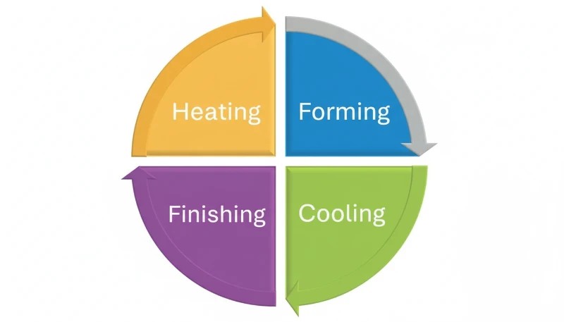
Bir enjeksiyon kalıbı soğutma sistemi, enjeksiyondan sonra erimiş plastikten ısıyı uzaklaştıran ve döngü süresi1 50-70% ile ve boyutsal doğruluğu sağlayarak. Doğru tasarlanmış bir soğutma sistemi olmadan, parçalar eğrilir, çökme izleri ortaya çıkar ve üretim verimi düşer. Soğutma sistemi sonradan düşünülen bir şey değildir — kalıbınızın kârlı mı yoksa bir yük mü olduğunu belirler.
Soğutma, boşluğu çevreleyen kalıp plakalarına delinmiş veya basılmış kanallardan dolaştırılan sıcaklık kontrollü bir ortam — en yaygın olarak 10-25 derece C'de su — ile çalışır. Erimiş plastikten gelen ısı (malzemeye bağlı olarak 180-320 derece C'de enjekte edilir), soğutucu sıvıya aktarılır ve bu sıvı ısıyı harici bir soğutucuya veya soğutma kulesine taşır. Parça, çıkarma sıcaklığına (tipik olarak malzemenin cam geçiş sıcaklığının 40-80 derece C altı) ulaşır ve çıkarılır.
Çin'deki fabrikamızda, 3 atölyede 47 enjeksiyon kalıplama makinesi çalıştırıyoruz. Ürettiğimiz her kalıp, sırasında özel bir soğutma devre düzeni alır DFM2 inceleme ve kullanıyoruz kalıp akış analizi3 herhangi bir çelik işlenmeden önce sıcaklık dağılımını simüle etmek için. Bu disiplin, ilk geçiş onay oranımızın 'yi aşmasının nedenidir.
Soğutma Sistemi Tasarımının Önemi: Rakamlar
Standart termoplastik enjeksiyon kalıplamada soğutma fazı, toplam döngü süresinin -70'ini oluşturur. 30 saniyelik bir döngüde soğutma süresinde 10 saniyelik bir azalma, 'lük bir verim artışına karşılık gelir — aynı makinede sıfır sermaye yatırımı ile yılda yüz binlerce daha fazla parça üretilir. Bu, enjeksiyon kalıplamada mevcut olan en yüksek ROI'ye sahip optimizasyondur.
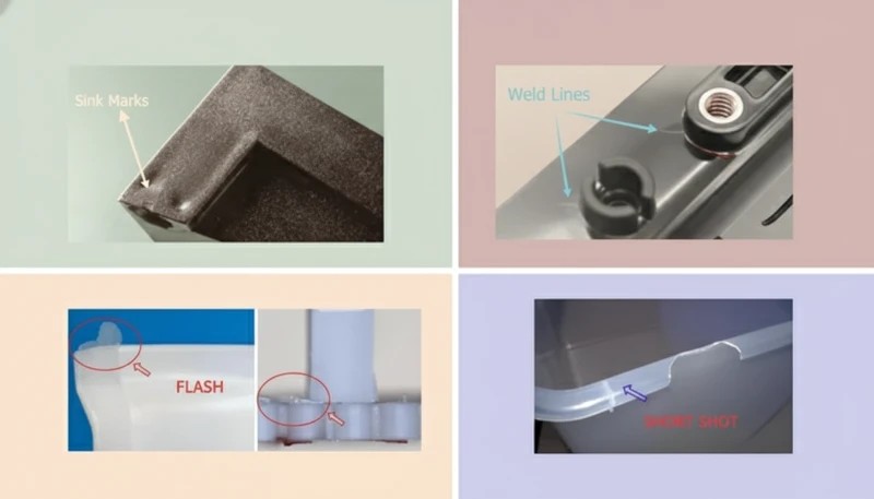
Zayıf soğutma tasarımı, birbirine bağlı beş sorun yaratır: boşluk yüzeyi boyunca 5 derece C'nin üzerindeki düzensiz sıcaklık gradyanlarından kaynaklanan eğrilme ve boyutsal sapma; yetersiz soğutma süresinin erken çıkarmaya neden olmasından kaynaklanan çökme izleri; hızlı veya düzensiz katılaşmadan kaynaklanan iç kalıntı gerilimi; parlaklık değişimi ve bulanıklık dahil yüzey kusurları; ve zayıf kanal yerleşimini telafi etmek için yapılan muhafazakar soğutma ayarlarından kaynaklanan uzamış döngü süreleri.
Beş sorunun tümü — hurda, yeniden işleme, yavaş döngüler veya başarısız müşteri denetimleri nedeniyle — para kaybına yol açar. Yüzlerce kalıp projesini incelediğimiz tecrübemize göre, zayıf soğutma tasarımı ilk parça başarısızlıklarının en yaygın kök nedenidir. Müşteriler genellikle başarısızlıkları malzemeye veya makine ayarlarına atfederken, asıl neden uygun şekilde tasarlanmamış bir soğutma devresidir.
| Parametre | Zayıf Soğutma | Optimize Edilmiş Soğutma | Improvement |
|---|---|---|---|
| Çevrim süresi | 35 sn | 22 saniye | -37% |
| Sıcaklık düzgünlüğü | >10°C delta | <3°C delta | 3 kat daha iyi |
| Eğilme (tipik ABS parça) | 0.8 mm | 0.15 mm | 81% azalma |
| Çökme izi derinliği | 0.3 mm | <0,05 mm | 6 kat daha iyi |
| Yıllık üretim kapasitesi (1 boşluk) | 825.000 atış | 1.310.000 atış | +59% |
Bu rakamlar, mühendislik ekibimizin 200'den fazla kalıp projesi üzerinden yaptığı dahili kıyaslama verilerinden gelmektedir. Kesin sayılar malzemeye, duvar kalınlığına ve parça geometrisine göre değişir — ancak yönlendirici etki tutarlıdır: kazanılan her saniye soğutma süresi doğrudan maliyet azaltımına ve kapasite artışına dönüşür.
6 Tip Enjeksiyon Kalıbı Soğutma Sistemi
Enjeksiyon kalıpları, her biri farklı parça geometrilerine, hassasiyet gereksinimlerine ve bütçe kısıtlamalarına uygun altı ana soğutma kanalı konfigürasyonu kullanır. Her tipin ne zaman kullanılacağını anlamak, kalıp tasarımının temelidir.
1. Düz Hat Soğutma Kanalları
Düz çizgi (veya delikli) soğutma kanalları, düz veya basit geometrili parçalar için standarttır; kalıp plakalarına ızgara veya paralel desende 6-14 mm çapında delikler delinerek oluşturulur. Kanal-boşluk mesafesi tipik olarak P20 çelik kalıplar için 15-25 mm'dir, boşluk yüzeyine minimum duvar kalınlığı kanal çapının 1,5 katıdır. Soğutucu akış hızı, türbülanslı akışı (Reynolds sayısı 10.000'in üzerinde) hedefler; bu, laminar akışa göre ısıyı 3-5 kat daha verimli bir şekilde aktarır.
Düz kanallar en uygun maliyetli seçenektir — devre başına delme maliyeti $50-200 iken, konformal kanallar için $500-5.000'dir — ve düz kapaklar, paneller, düzgün duvar kalınlığına sahip muhafazalar ve tüketim malları parçaları için tamamen uygundur. Sınırlamaları geometriktir: eğri veya karmaşık boşluk yüzeylerini takip edemezler, bu da köşelerde ve kanalın boşluk duvarından zorunlu olarak daha uzak olduğu nervürlerde sıcak noktalar bırakır.
2. Baffle Soğutma
Bafflelar, delinmiş kanallara yerleştirilen ince metal plakalardır ve soğutucuyu bir taraftan aşağı, diğer taraftan yukarı akmasını sağlayarak tek bir düz deliği U şeklinde bir akış yoluna dönüştürür. Dar çekirdeklerde, pimlerde ve yan yana iki paralel kanalın delinemeyeceği alanlarda kullanılırlar. Tipik bir baffle, ek kanal portu gerektirmeden kısıtlı bir bölgede soğutma yüzey alanını iki katına çıkarır.
Baffle etkinliği, plaka boşluğuna (her iki tarafta 0,05-0,15 mm) ve soğutucu akış hızına bağlıdır. Genellikle 16 ila 40 mm arasındaki herhangi bir çekirdek çapı için baffle belirtiriz. 16 mm'nin altında termal pimler veya bubblar daha etkilidir; 40 mm'nin üzerinde spiral kanallar tercih edilen seçenek haline gelir. Baffle geometrisi ve uygun akış hızının kombinasyonu, yeterli ve mükemmel çekirdek soğutması arasındaki farkı yaratır.
3. Havalandırıcı Soğutma
Fıskiyeler (aynı zamanda çeşme soğutması olarak da adlandırılır), kör bir deliğe yerleştirilmiş küçük çaplı bir iç tüp kullanır: soğutucu sıvı iç tüpten aşağı akar ve tüp ile delik duvarı arasındaki halkasal boşluktan yukarı döner. Bu, çekirdeğin ucunda — en sıcak bölgede — bir püskürtme etkisi yaratır ve çok yüksek yerel ısı transfer katsayıları elde edilir. Fıskiyeler, 16 mm çapın altındaki çekirdekler ve en-boy oranı 4:1'in üzerinde olan derin pim özellikleri için standarttır.
Dükkanımızda, çapı ne olursa olsun, 25 mm yüksekliğin üzerindeki her çekirdek piminde havalandırıcı kullanıyoruz. Her havalandırıcı portu için $30 80 ek işleme maliyeti, kalıp denemesinde döngü süresi azaltılarak sürekli olarak telafi edilir. Havalandırıcılar için çok küçük olan çekirdeklerde, berilyum bakır ekler pasif ısı iletimi sağlayarak yakındaki su kanallarına ısıyı iletir.
4. Spiral (Heliks) Soğutma Kanalları
Spiral cooling channels wrap a helical path around cylindrical cores or circular cavities, providing uniform cooling over 360 degrees of the feature. For threaded closures, round containers, medical vials, and any rotationally symmetric part, spiral channels reduce peak-to-average temperature differential from more than 8 degrees C (with straight channels) to less than 2 degrees C.
Pitch and lead angle are tuned to the coolant flow rate — typically 4-8 mm pitch with a 45-degree helix angle for water cooling. Spiral inserts can be machined as separate components and pressed into mold cores, making them replaceable when worn or when geometry changes require a redesign.
5. Conformal Cooling Channels
conformal cooling4 channels follow the exact 3D contour of the mold cavity wall at a uniform standoff distance (typically 5-12 mm), made possible by metal additive manufacturing (DMLS or SLM). Where conventional drilled channels leave hot spots on curved surfaces and sharp corners, conformal channels maintain cavity-to-channel distance within plus or minus 1 mm across the entire surface — delivering 20-35% cycle time reduction and dramatically more uniform cooling.
The trade-off is cost and lead time: a conformal-cooled insert produced by DMLS from H13 tool steel costs $3,000-15,000 versus $500-2,000 for a conventionally machined insert. The break-even point is typically reached at 50,000-100,000 shots for high-volume parts, where cycle time savings translate to machine-hour savings that exceed the tooling premium. For medical devices, automotive trim, and consumer electronics at high volume, conformal cooling is the standard of practice.
6. Thermal Pins and Heat Pipes
Thermal pins (heat pipes) are sealed copper or beryllium copper components charged with a phase-change fluid. They passively transfer heat from hot spots — sharp corners, ribs, thin features — to a water-cooled heat sink with no active coolant flow. Heat pipe thermal conductivity reaches 10,000-100,000 W/m·K, compared to 20-50 W/m·K for P20 steel.
Thermal pins are ideal for features too small or inaccessible for active cooling channels, such as ribs under 3 mm wide or ejector pin areas. They require no plumbing connections and can be retrofitted into existing molds without major rework. In our factory, thermal pins have eliminated hot-spot sink marks on several medical device molds where ribs could not otherwise be adequately cooled.
Soğutma Ortamı Karşılaştırması: Su, Yağ ve Hava
The cooling medium choice — water, oil, or air — determines heat transfer capacity, operating temperature range, maintenance requirements, and cost. Each medium fits a specific window of mold temperature requirements, and choosing the wrong medium creates quality problems that are surprisingly difficult to trace back to their root cause.
| Orta | Temp Range | Heat Transfer | İçin En İyisi | Bakım |
|---|---|---|---|---|
| Water (chilled) | 10-60°C | High (3,000-10,000 W/m2K) | Most thermoplastics (PE, PP, ABS, PC) | Scale/corrosion control |
| Water (tower) | 25-35°C | Yüksek | High-volume commodity parts | Algae and mineral control |
| Oil (thermal) | 60-200°C | Medium (500-2,000 W/m2K) | High-temp materials (PEI, PEEK, PPS) | Fluid replacement every 12 months |
| Hava | Ambient | Low (50-200 W/m2K) | Thin walls, elastomers, foam parts | Minimal — filter cleaning only |
| Beryllium copper | Passive | Very high (conduction) | Thin ribs, micro features | None |
In our factory, 90% of molds run water cooling at 15-25 degrees C using a closed-loop chiller system. For engineering resins processed above 120 degrees C (PEI, PEEK, PPS, POM), we switch to temperature-controlled oil circuits that maintain mold temperature at 80-160 degrees C. Air cooling is reserved for simple silicone and thin-wall foam applications where water channel proximity would cause surface condensation.
Water chemistry management is a critical and often overlooked aspect of mold cooling. We use deionized water with pH 7-8 and a corrosion inhibitor package in all production chiller loops. Tap water causes progressive scale buildup that reduces heat transfer by 15-25% per millimeter of deposit — an invisible performance degradation that shows up as gradually increasing cycle times over 12-18 months of production.
Doğru veya Yanlış: Enjeksiyon Kalıp Soğutma Efsaneleri
“Cooling time accounts for more than half of total injection molding cycle time.”Doğru
In most standard thermoplastic applications, cooling accounts for 50-70% of total cycle time. A 30-second cycle typically breaks down as: injection 3-5 sec, pack/hold 5-8 sec, cooling 15-22 sec, and ejection/mold-open 3-5 sec. Optimizing the cooling phase is the single highest-leverage action in cycle time reduction. Even a 20% improvement in cooling efficiency on a 20-second cooling window saves 4 seconds — a 13% cycle time reduction with no other changes.
“Using colder water always produces faster, better results in injection mold cooling.”Yanlış
Dropping coolant temperature below the dew point causes condensation on the mold surface — forming water droplets that transfer to part surfaces as cosmetic defects, accelerate mold surface rust, and cause short shots. For hygroscopic materials like nylon and ABS, mold temperature must stay above 15 degrees C to prevent moisture-related defects. The optimal coolant temperature depends on material, wall thickness, ambient humidity, and surface finish requirements — not simply the lowest achievable temperature.
These two principles — that cooling dominates cycle time and that coolant temperature must be carefully controlled — form the foundation of effective injection mold cooling system engineering. Misunderstanding either one leads to wasted machine time or cosmetic defects that fail customer inspection. The next two myths address more advanced design decisions around coolant flow dynamics and cooling technology selection. Both are frequently misapplied in practice: engineers either accept laminar flow as unavoidable or invest in conformal cooling for parts that do not justify the premium. Getting the analysis right saves both time and money.
“Turbulent coolant flow transfers heat significantly more efficiently than laminar flow.”Doğru
Turbulent flow (Reynolds number above 10,000) achieves convective heat transfer coefficients of 3,000-10,000 W/m2K, compared to 500-1,500 W/m2K for laminar flow — a 3-5 times improvement in heat transfer rate. Achieving turbulence requires minimum flow velocities of 0.5-1.0 m/s for 8 mm channels. We specify flow rate requirements on every mold cooling circuit drawing and verify turbulent conditions at the mold trial using digital flow meters on each circuit port.
“Conformal cooling channels always justify their higher cost over conventional straight channels.”Yanlış
Conformal cooling is a premium solution justified only by high production volumes and geometrically complex parts. For flat panels, lids, and simple boxes running under 50,000 shots annually, the $10,000-30,000 DMLS tooling premium will never be recovered through cycle time savings. The break-even analysis must account for machine hourly rate, cycle time delta, annual volume, and tool life. For low-volume specialty parts, optimized straight channels deliver 90% of the benefit at 10% of the cost.
Enjeksiyon Kalıbı Soğutması için Temel Tasarım Parametreleri
Five engineering parameters govern cooling system performance. Getting these right at the design stage prevents expensive rework after mold trials. These numbers are not arbitrary — they emerge from decades of empirical testing and thermal simulation validation.
Channel Diameter
Standard cooling channel diameters range from 6 mm (small precision molds) to 16 mm (large structural molds). The most common sizes in our shop are 8 mm and 10 mm, which balance drilling cost, flow resistance, and heat transfer surface area. Channels below 6 mm are prone to blockage from scale and corrosion and require filtered deionized water; channels above 16 mm reduce structural mold strength and increase the risk of channel-to-channel breakthrough during drilling.
Channel-to-Cavity Distance
Channel centerline-to-cavity surface distance should be 1.5-2 times the channel diameter for balanced thermal and structural performance. For an 8 mm channel in P20 steel, the target distance is 12-16 mm. Closer placement increases cooling rate but risks stress cracking and core breakthrough; greater distances reduce cooling efficiency and create hot spots between channels where the thermal gradient is not adequately controlled.
Channel Pitch (Center-to-Center Spacing)
Pitch between parallel channels affects temperature uniformity across the cavity surface. The standard recommendation is 3-5 times the channel diameter. For 10 mm channels, a pitch of 30-50 mm balances thermal uniformity against drilling cost. Wider pitch produces temperature ripple between channels; tighter pitch is structurally challenging and increases the mold plate cost.

Soğutucu Akış Hızı ve Reynolds Sayısı
Türbülanslı akış için Reynolds sayısının 10.000'in üzerinde olması gereken akış hızı. 8 mm'lik bir kanal için bu, devre başına yaklaşık 2,6 litre/dakikaya karşılık gelen 0,7 m/s'nin üzerinde akış hızı gerektirir. Standart uygulamamız, her devre portuna takılan dijital akış ölçerler kullanarak kalıp denemesinde akış hızını doğrulamak ve gelecekteki üretim referansı için kalıp kurulum sayfasına gerçek Reynolds sayılarını kaydetmektir.
Giriş ve Çıkış Sıcaklık Farkı
Soğutucu giriş-çıkış sıcaklık artışı devre başına 3-5 derece C'nin altında kalmalıdır. Daha büyük bir delta yetersiz debiyi gösterir — soğutucu her geçişte çok fazla ısı emiyor — ve parçanın bir ucundan diğerine eşit olmayan soğutmaya yol açan kanal boyunca bir sıcaklık gradyanı oluşturur. Standart olarak 3 derece C'nin altında bir delta hedefliyoruz ve bu sağlanana kadar denemede debiyi ayarlıyoruz.
Adım Adım Soğutma Sistemi Tasarım Süreci
Mühendislik ekibimiz, her yeni kalıp soğutma sistemi için, başlangıç CAD incelemesinden kalıp deneme validasyonuna kadar yapılandırılmış bir yedi adım süreci izler. Bu süreç, soğutma ile ilgili çoğu ilk parça hatasını ortaya çıkmasını engeller.
Adım 1 termal yük hesaplamasıdır: enjekte edilen plastik kütleden, malzeme entalpisinden ve döngü süresi hedefinden gelen ısı girdisini tahmin ederek watt cinsinden gerekli soğutma kapasitesini tanımlayın. Adım 2 kanal tipi seçimidir: kanal geometrisini parça şekline uydurun — düz parçalar için düz, silindirik özellikler için spiral, karmaşık 3D geometri için uyumlu, dar gövdeler için engeller ve hava üfleyiciler. Adım 3 yerleşim tasarımıdır: kanalları 1,5-2 kat çap mesafesinde, 3-5 kat aralıkla ve kanallar arasında yeterli çelik köprülerle konumlandırın.
Adım 4 devre planlamasıdır: akışı dengede tutmak ve soğutucu hızının sıfıra düştüğü ölü bölgelerden kaçınmak için seri ve paralel devreleri tasarlayın. Adım 5 kalıp akış simülasyonudur: Moldex3D veya Moldflow'da termal analiz yaparak ısı uniformitesini kontrol edin, ısı odaklarını belirleyin ve warp tahmini yapın — layoutu, maksimum ve ortalama ısı farkı 5 derece C altına düşene kadar tekrar edin. Adım 6 DFM incelemesidir: ejector pinleri, leader pinleri, lifters ve slides ile drilling interference kontrol edin. Adım 7 kalıp deneme validasyonudur: infrared termometre ile devre akış hızları, inlet/outlet ısı farkı ve ejection parça ısısını ölçün, sonra simülasyon tahminleri ile karşılaştırın.
Yaygın Soğutma Sistemi Sorunları ve Çözümleri
İyi tasarlanmış soğutma sistemleri bile zamanla sorunlar geliştirir. Fabrikamızda karşılaştığımız en sık üç sorun, kanal kireçlenmesi, tasarım kör noktalarından kaynaklanan sıcak noktalar ve soğutucunun kalıp boşluğuna sızmasıdır. Her birinin net teşhis göstergeleri ve kanıtlanmış çözümleri vardır.
| Problem | Karşı yüzeyde çökme izlerini önler | Çözüm |
|---|---|---|
| Eğilme / boyutsal sapma | Düzensiz boşluk sıcaklığı (>5°C delta) | Isı odaklarına kanallar ekleyin; akış dengesini kontrol edin |
| Kireçlenme/tıkanmış kanallar | Sert su mineral tortuları | Deiyonize su kullanın; yıllık asit temizliği |
| Soğutucu sızıntısı boşluğa | Çatlak kanal duvarı (yetersiz çelik kalınlığı) | >10 mm wall ile yeniden tasarlayın; insertlerde O-ringler kullanın |
| Uzatılmış döngü süresi | Yetersiz debi (laminer akış) | Pompa basıncını artır; devre uzunluğunu azalt; kanalları yeniden boyutlandır |
| Yüzey kondensasyonu/pas | Çiy noktasının altında soğutucu | Soğutucu sıcaklığını yükselt; nem bariyerleri kullan |
| Kaburgalar/ince duvarlarda sıcak noktalar | Kanal özellikten çok uzak | Etkilenen bölgelere hava üfleyiciler, engeller veya termal pimler ekleyin |
Tecrübelerimize göre kireç birikimi uzun vadeli bir numaralı soğutma katilidir. Bir kanal duvarında 1 mm kireç tabakası ısı transferini yaklaşık -25 azaltır. Tüm üretim kalıplarında çeyrek dönem soğutma devresi kontrollerini zorunlu kılıyoruz ve su sertliğine bağlı olarak her 6-12 ayda bir asitli kireç çözme uyguluyoruz. Şehir suyu ile çalışan kalıplar, deiyonize su döngülerinde çalışanlara göre daha sık bakım gerektirir.
Soğutucu sızıntısının kalıp boşluğuna sızması daha az yaygındır ancak gerçekleştiğinde felaket derecede kesintiye neden olur — üretim hemen durur ve kalıbın onarılması gerekir. Ana neden, soğutma kanalı ile boşluk yüzeyi arasında yetersiz duvar kalınlığıdır, tipik olarak üretim sırasında çok yakına delinen bir kanaldan veya önceden var olan bir yüzey kusurundan yayılan bir çatlaktan kaynaklanır. DFM incelemesi sırasında minimum duvar kalınlığını doğrularız ve herhangi bir kalıp denemesinden önce, işleme sonrası CMM ölçümü ile tekrar doğrularız.
Konformal Soğutma vs. Geleneksel Soğutma: Ne Zaman Seçilmeli
Konformal soğutma her zaman doğru cevap değildir. Karar çerçevesi basittir: takımmaliyeti primi ile planlanan üretim hacmi üzerinden döngü süresi tasarrufunun değerini karşılaştırın. Bu analizi her iki yönde de yanlış yapmak para kaybettirir — ya düşük hacimli bir parça için premium takıma fazla harcama yaparak ya da yüksek hacimli bir parça için önemli döngü süresi tasarruflarını masada bırakarak.
| Faktör | Geleneksel'i Seçin | Konformal Seç |
|---|---|---|
| Parça geometrisi | Düz, tekdüze duvar kalınlığı | Karmaşık 3B, değişken duvar kalınlığı |
| Annual volume | <50,000 shots | >100.000 atış |
| Döngü süresi hedefi | Agresif kısıtlama yok | %+ azalma gerekiyor |
| Warp toleransı | +/-0,5 mm kabul edilebilir | <+/-0.2 mm gereklidir |
| Takım bütçesi | Standart bütçe | -50 prim kabul edilebilir |
| Malzeme | PE, PP, ABS (hoşgörülü) | PC/ABS, Naylon, mühendislik reçineleri (hassas) |
Fabrikamızda, otomotiv dış trim, tıbbi cihaz muhafazaları ve kozmetik standartların katı olduğu, duvar kalınlığının önemli ölçüde değiştiği ve yıllık hacmin 100.000 atışı aştığı tüketici elektroniği parçaları için uyumlu soğutma öneriyoruz. Ambalaj, standart muhafazalar ve prototip takımlar için optimize edilmiş geleneksel soğutma, maliyetin çok daha azıyla gerekli kaliteyi sağlar. Karar, DFM incelemesinde alınmalıdır — ilk kalıp denemesinde bir döngü süresi sorunu ortaya çıktıktan sonra değil.
Konformal Soğutma Teknolojisinin Gelişen Maliyeti
Konformal soğutmanın ekonomisi, DMLS (Doğrudan Metal Lazer Sinterleme) makine maliyetlerinin -60 oranında düşmesi ve teslim sürelerinin 8 haftadan 2-3 haftaya sıkışmasıyla son beş yılda önemli ölçüde değişmiştir. 2020'de konformal soğutma öncelikle otomotiv ve tıbbi uygulamalar için haklı görülüyordu. Bugün, duvar kalınlığı varyasyonu 2:1'in üzerinde olan ve yıllık hacmi 75.000 atımı aşan herhangi bir parça için giderek daha fazla tavsiye ediyoruz. Başabaş noktası hesaplaması artık sık sık, sadece birkaç yıl önce geleneksel kanallara başvurulacak uygulamalarda konformal soğutmadan yana sonuçlanıyor.
Konformal soğutmanın az takdir edilen bir avantajı, sadece hız değil, aynı zamanda parça tutarlılığı üzerindeki etkisidir. Sıcaklık dağılımı 2-3 derece C dahilinde üniform olduğunda, atımdan atıma boyutsal varyasyon önemli ölçüde azalır — bu, Cpk gereksinimlerinin 1.67'nin üzerinde olduğu tıbbi cihaz imalatı ve hassas otomotiv bileşenlerinde son derece önemli bir faktördür. Fabrikamızda, üç tıbbi cihaz kalıbını gelenekselden konformal soğutmaya geçirmek, boyutsal proses varyasyonunu -45 oranında azaltarak müşteri seviyesinde önemli bir denetim reddi kaynağını ortadan kaldırdı.

Enjeksiyon Kalıp Soğutma Sistemleri Hakkında Sıkça Sorulan Sorular
Enjeksiyon kalıplamada soğutma süresi ne kadar olmalıdır?
Soğutma süresi, duvar kalınlığına, malzemenin ısıl iletkenliğine, kalıp sıcaklığına ve gerekli ejeksiyon sıcaklığına bağlıdır. Genel kural şudur: saniye cinsinden soğutma süresi yaklaşık olarak milimetre cinsinden duvar kalınlığının karesine eşittir, amorf reçineler (ABS, PC) için 1.5-2.5, yarı kristal reçineler (PP, PA, POM) için 2.0-4.0 malzeme faktörü ile çarpılır. 3 mm ABS duvar için 9-13 saniye soğutma; 3 mm PP duvar için 18-36 saniye soğutma bekleyin. Mühendislik ekibimiz, DFM incelemesi sırasında gerekli soğutma süresini sadece genel kurallarla değil, ısıl simülasyon araçlarını kullanarak hesaplar — çünkü tek bir parça üzerindeki duvar kalınlığı varyasyonu, farklı bölümler için çok farklı soğutma süreleri gerektirebilir.
Enjeksiyon kalıplama parçalarında neden eğilme oluşur?
Bükülme, parçada düzensiz soğutma nedeniyle oluşan farklı büzülmeden kaynaklanır. Bir yüzey karşıt yüzeyden daha hızlı soğuduğunda, daha fazla büzülür ve parçayı daha soğuk tarafa doğru eğer. Kalıp boşluğu ve çekirdek tarafları arasında 5-8 derece C'nin üzerindeki sıcaklık gradyanları en yaygın kök nedenidir. Diğer katkıda bulunan faktörler arasında asimetrik duvar kalınlığı, yetersiz dolum basıncı, giriş yeri ve cam dolgulu malzemelerdeki lif yönlendirme etkileri bulunur. Temel çözüm, soğutma devresi düzenini dengelemektir — bu, herhangi bir çelik kesilmeden önce termal simülasyonlu akış analizi ile doğrulanır. Kök neden soğutma tasarımında ise, bükülmeyi yalnızca dolum basıncı ayarlamalarıyla düzeltmeye çalışmak nadiren başarılı olur.
Soğutma kanalı çapı ve aralığı nasıl hesaplanır?
Soğutma kanalı tasarımı için standart endüstri kılavuzları: kanal çapı 6-16 mm olmalıdır (genel takımlar için en yaygın 8-10 mm); kanal merkez çizgisinden boşluk yüzeyine olan mesafe kanal çapının 1.5-2.0 katı olmalıdır; kanal aralığı (merkezden merkeze mesafe) kanal çapının 3-5 katı olmalıdır. 10 mm çapında bir kanal için boşluk mesafe hedefi 15-20 mm, aralık ise 30-50 mm'dir. Bu başlangıç parametreleri, herhangi bir çelik işlenmeden önce, tam üretim koşullarında tüm boşluk yüzeyi boyunca tepe-ortalama sıcaklık değişiminin 5 derece C'nin altında kaldığını doğrulamak için Moldex3D veya Moldflow kullanılarak termal simülasyonla doğrulanır.
Seri ve paralel soğutma devreleri arasındaki fark nedir?
Seri bir devrede, soğutucu sıvı, kalıptan çıkmadan önce tüm kanallardan tek bir kesintisiz yol boyunca akar. Bu, tesisat döşemesi açısından basittir ancak soğutucu sıcaklığının girişten çıkışa kadar önemli ölçüde yükselmesine izin vererek, parça uzunluğu boyunca üniform olmayan soğutmaya neden olan bir sıcaklık gradyanı oluşturur. Paralel bir devrede, soğutucu akışı aynı anda birden fazla kanala bölünür ve çıkış manifoldunda yeniden birleştirilerek, kalıp boyunca daha üniform sıcaklık dağılımı sağlanır. Çoğu üretim kalıbı, her bölgede üniform soğutucu giriş sıcaklığı elde etmek için tüm kalıp boyunca paralel manifoldlar aracılığıyla dengelenmiş, bireysel bölgeler için kısa seri devreler içeren bir kombinasyon yaklaşımı kullanır.
Soğutma sistemim var ama kalıbımda neden ısı odakları oluşuyor?
Sıcak noktalar, soğutma kanallarının boşluk yüzeyinden çok uzak olduğunda, akış hızının yetersiz olup laminer akış koşulları oluşturduğunda, kireç birikiminin kanalları etkili ısı transferinden yalıttığında veya belirli özelliklerin — ince nervürler, keskin köşeler, küçük çekirdekler — geleneksel kanallarla ulaşılamadığı durumlarda oluşur. Çözümler arasında ulaşılamayan özelliklere hava kabarcıklı soğutucular veya termal pimler eklemek, deneme aşamasında dijital akış ölçerlerle türbülanslı akış koşullarını doğrulamak, tüm devrelerde yıllık asitli kireç çözme işlemi yapmak ve ejeksiyon sonrası kızılötesi parça sıcaklığı haritalaması ile tespit edilen kronik sıcak bölgelerde konformal soğutma insertlerine yükseltme yapmak yer alır.
-
cycle time: Döngü süresi, enjeksiyon, soğutma ve çıkarma aşamalarını kapsayan, saniye cinsinden ölçülen bir tam enjeksiyon kalıplama döngüsünün toplam süresidir. ↩
-
DFM: DFM (Üretilebilirlik için Tasarım), üretim sürecinin verimliliğini ve maliyet etkinliğini iyileştirmek için ürün tasarımını optimize eden bir mühendislik metodolojisidir. ↩
-
mold flow analysis: Kalıp akış analizi, erimiş plastiğin bir kalıp boşluğunu nasıl doldurduğunu, soğutma davranışı, eğilme ve büzülme dahil olmak üzere tahmin eden bir bilgisayar simülasyonu sürecidir. ↩
-
conformal cooling: Konformal soğutma, kanalların kalıp boşluğunun konturunu takip edecek şekilde tasarlandığı, karmaşık parça geometrileri boyunca üniform ısı uzaklaştırmaya olanak tanıyan bir kalıp soğutma tekniğini ifade eder. ↩


