 İçeriğe geç

Injection molding is a cyclic process — every part is born from a repeating sequence of injection, packing, cooling, and ejection. The total time for one complete loop is the Çevrim süresi1, and it directly controls your production rate and per-part cost. In our Shanghai factory, we have spent over 20 years fine-tuning cycle times across thousands of molds. This guide breaks down the calculation method so you can estimate, measure, and optimize cycle time on your own projects.
- Cycle time = injection + packing + cooling + ejection + mold open/close
- Cooling typically accounts for 60–70% of total cycle time
- Wall thickness is the single biggest driver of cooling duration
- A 1-second reduction can yield 100,000+ extra parts per year on a multi-cavity mold
- Proper mold cooling design is the most cost-effective optimization
What Is Cycle Time in Injection Molding?
Cycle time is the total elapsed time from the start of one injection shot to the start of the next. It measures how fast your machine can produce parts — and it’s the single most important metric for enjeksiyon kalıbıing productivity.
Think of it this way: if you’re running a 4-cavity mold with a 30-second cycle, that’s roughly 480 parts per hour. Shrink that to 25 seconds, and you jump to 576 — a 20% production boost with zero additional capital investment. That’s why experienced engineers obsess over every second.
The formula is straightforward in concept: t_cycle = t_inject + t_pack + t_cool + t_open + t_eject + t_close. In practice, some phases overlap. Screw recovery2 (plasticizing the next shot) happens during cooling, so you take the longer of t_cool and t_screw_recovery rather than adding both.
Cycle time isn’t a fixed property — it changes with material, part geometry, mold design, and machine settings. A thin-wall PP cap might cycle in 5–8 seconds, while a thick-wall polycarbonate housing could take 60 seconds or more. Engineers often talk about “optimal cycle time” — the fastest repeatable cycle that still produces parts meeting all quality specs. Push too fast, and you get short shots, sink marks, or dimensional drift. Push too slow, and you’re bleeding money on machine time.
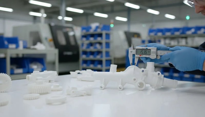
How Do You Calculate Cycle Time Step by Step?
The cycle time formula is the sum of injection, packing, cooling, and mold operation times. Some phases overlap — for example, screw recovery happens during cooling — so you take the longer duration rather than adding both.
Injection Time (t_inject)
This is how long it takes to fill the cavity with molten plastic. For most parts, it’s 0.5–5 seconds. You can estimate it as: t_inject = Part weight (g) ÷ Injection rate (g/s). For example, a 50g part on a machine delivering 100 g/s takes about 0.5 seconds to fill. But real injection profiles use multi-stage speeds (slow-fast-slow), so actual time is slightly longer than the theoretical minimum.
Packing/Holding Time (t_pack)
After the cavity fills, you maintain pressure to compensate for material shrinkage. This typically runs 1–10 seconds depending on wall thickness and gate freeze-off time. Thin parts freeze fast; thick parts need longer hold. The packing phase ends when the gate solidifies, sealing the cavity.
Cooling Time (t_cool)
This is where most of your cycle lives. For semi-crystalline materials, Soğutma süresi3 is roughly proportional to the square of wall thickness: t_cool ≈ C × (wall thickness)², where C depends on material thermal diffusivity and the temperature difference between melt and mold. For a 3mm wall in ABS, expect 15–25 seconds. For a 5mm wall, it jumps to 40–60 seconds.
Mold Open/Close and Ejection
Mold open and close typically takes 2–10 seconds depending on mold size and press tonnage. Small molds on 80–200T presses run 2–4 seconds; large molds on 500–1000T presses take 6–12 seconds. Ejection time adds 0.5–3 seconds, with automated pickers being faster than manual removal.
Putting It All Together
Here’s a sample calculation for a mid-size ABS housing (3mm wall, 80g, 4-cavity mold on a 200T press): t_inject ≈ 1.5s, t_pack ≈ 3s, t_cool ≈ 20s, t_open + t_eject + t_close ≈ 5s. Total cycle time: approximately 29.5 seconds. In production, we’ve seen cycles range from 5 seconds for thin-wall packaging to over 90 seconds for thick technical parts.
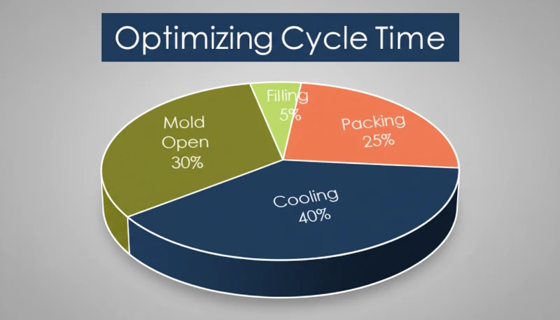
What Are the Four Phases of an Injection Molding Cycle?
The four phases are injection (filling), packing (holding), cooling, and ejection/reset. Each has a distinct role in part quality and cycle efficiency.
Phase 1 — Injection (Filling)
The screw pushes forward, forcing molten plastic through the runner and gate into the cavity. Speed is critical — too slow and the melt freezes before filling; too fast and you get jetting or flash. Injection time is typically the shortest phase, but it sets the foundation for part quality.
Phase 2 — Packing (Holding)
Once the cavity is volumetrically full, the machine switches to holding pressure. This extra pressure packs in additional material to compensate for thermal shrinkage as the part cools. Packing continues until the gate freezes off, sealing the cavity. Getting packing time wrong is a common source of sink marks and voids.
Phase 3 — Cooling
The mold maintains a controlled temperature (usually 20–80°C depending on material), pulling heat out of the part until it’s rigid enough to eject without deformation. This phase runs the longest — often 60–70% of total cycle time. Meanwhile, the screw retracts and plasticizes the next shot, so cooling and screw recovery overlap.
Phase 4 — Ejection and Reset
The mold opens, the part is ejected (mechanically or by robot), and the mold closes for the next shot. Ejection can be a bottleneck if parts stick or if manual inspection is required. Well-designed ejector systems and proper draft angles keep this phase predictable.
In our Shanghai factory, we run 47 injection molding machines from 90T to 1850T. With over 20 years of production experience across more than 400 materials, we’ve optimized cycle times from fast-cycling PP packaging parts at 8 seconds to thick-wall PC components at 60+ seconds. Every machine logs cycle data shot by shot for continuous improvement.
Why Does Cooling Time Dominate the Cycle?
Cooling is the dominant phase, consuming 60–70% of total cycle time because heat extraction from thick polymer walls takes longer than any other step.
The polymer melt enters the cavity at 200–300°C, and you need to pull it down to 40–80°C before it’s safe to eject. The heat transfer rate depends on several factors.
Wall Thickness — The Big One
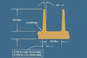
Cooling time scales roughly with the square of the thickest section. A part that’s 4mm thick needs about 1.8× the cooling time of a 3mm part. This is why DFM reviews always push for minimum uniform wall thickness.
Material Thermal Conductivity
Amorphous materials like PC and ABS cool differently than semi-crystalline ones like PA and POM. Crystalline materials release latent heat during solidification, which adds to cooling time. Material choice isn’t just about part performance — it directly impacts production economics.
Mold Temperature and Cooling Channel Design
Lower mold temperature pulls heat faster, but too cold causes residual stress, warpage, or poor surface finish. Well-placed baffle circuits, heat pipes, or conformal cooling channels can cut cooling time by 20–40% compared to basic drilled channels. This is where mold engineering pays for itself.

Pratik çıkarım: döngü süresini azaltmak istiyorsanız, önce soğutmayı hedef alın. Tek tip duvar kalınlığı (varyasyonları % altında tutun), optimize edilmiş soğutma kanalı düzeni ve uygun su akış hızları size en büyük getiriyi sağlar.
Döngü Süresini En Çok Hangi Faktörler Etkiler?
En büyük faktörler, kabaca bu sırayla, duvar kalınlığı, malzemenin termal özellikleri, kalıp soğutma tasarımı ve makine kapasitesidir.
Parça geometrisi en önemli etkendir. Daha kalın duvarlar, katlanarak daha uzun soğuma süresi demektir. Derin nervürler, çıkıntılar veya değişken kalınlık bölümleriyle karmaşık parça geometrileri, sıcak noktalar oluşturarak tüm döngüyü en yavaş soğuyan bölge için uzatmanızı gerektirir.
Malzeme seçimi önemlidir çünkü farklı polimerlerin farklı termal özellikleri vardır. PP ve PE nispeten hızlı soğur. PC, PPSU ve takviyeli naylonlar daha fazla zamana ihtiyaç duyar. Döngü süresi kritikse ve performans izin veriyorsa, PC'den ABS'ye geçmek soğutma süresini –40 oranında kesebilir.
Kalıp tasarımı, kazandığınız veya kaybettiğiniz yerdir. Anahtar faktörler arasında soğutma kanalı yerleşimi ve akış hızı, geçit türü ve konumu, çıkarma sistemi güvenilirliği ve kalıp malzemesi seçimi bulunur. Berilyum bakır ek parçaları ısıyı çelikten 3–5 kat daha hızlı iletir ve sıcak nokta alanları için mükemmeldir. Makine ayarları size artımlı kazançlar sağlar — daha yüksek enjeksiyon hızı, optimize edilmiş tutma profilleri ve daha hızlı kalıp açma/kapama hızları hepsi yardımcı olur, ancak bunlar tasarım ve kalıp mühendisliğine kıyasla ince ayarlardır.
“Soğutma süresi tipik olarak enjeksiyon kalıplama döngü süresinin –70'ini oluşturur.”Doğru
Doğru. Fabrikamızdaki binlerce üretim çalışmasında, soğutma süresi tutarlı bir şekilde döngüyü domine eder. Hızlı döngülü ambalaj kalıplarında bile, soğutma hâlâ en uzun tek aşamadır.
“Enjeksiyon hızını artırmak her zaman toplam döngü süresini azaltır.”Yanlış
Yanlış. Optimum noktanın ötesinde, daha hızlı enjeksiyon, uzatılmış paketleme ve soğutma gerektiren parlama, fışkırma veya hava tuzaklarına neden olur. Enjeksiyon hızını çok fazla artırırsanız net döngü süresi aslında artabilir.
Kaliteden Ödün Vermeden Döngü Süresini Nasıl Optimize Edebilirsiniz?
Önce soğutma optimizasyonuna, sonra duvar kalınlığı azaltmaya, ardından makine ayarına odaklanın — etki sırasına göre. İşte üretimde kullandığımız en etkili stratejiler.
Soğutma Kanallarını Yeniden Tasarla
Bu, tek en yüksek geri dönüşüm değişikliğidir. Kalıbınızda temel düz delikli kanallar varsa, baffle'lara, bublerlara veya spiral kanallara geçiş yapmak soğutma süresini –30 oranında azaltabilir. Yüksek hacimli kalıplar için, uyumlu soğutma (metal 3D baskı ile mümkün kılınmıştır) + azalmalar elde edebilir.
Duvar Kalınlığını En Aza İndirin ve Tekdüze Hale Getirin
Maksimum duvar kalınlığındaki her 0.5mm'lik azalma, soğutma süresini –20 oranında kesebilir. Parça boyunca duvar kalınlığı varyasyonunu 'in altında tutun. Tasarım ekibinizle erken çalışın — Tasarım üretilebilirlik analizi (DFM) değişiklikleri kalıp kesilmeden önce ucuz, sonra pahalıdır.
Besleme Yeri ve Tipini Optimize Et
Daha iyi geçit yerleşimi eşit dolumu sağlar ve uzatılmış paketleme süresi ihtiyacını azaltır. Valfli geçitlere sahip sıcak kanal sistemleri daha hızlı döngüleme sağlar çünkü soğutma fazından bağımsız olarak kapatırlar.
Çıkarmayı Otomatikleştir
Robotik toplayıcılar veya otomatik düşürme sistemleri, manuel parça çıkarmanın değişkenliğini ortadan kaldırır. Bu özellikle insan tepki süresinin darboğaz haline geldiği 15 saniyenin altındaki döngüler için etkilidir.
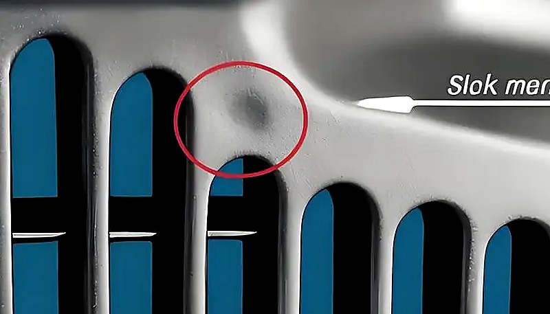
Uyarı: herhangi bir döngü süresi optimizasyonu kalite verileriyle doğrulanmalıdır. Döngü süresini azalttıktan sonra çökme işaretleri, boyutsal sapma veya eğrilme görürseniz, çok ileri gitmişsiniz demektir. Yeni bir döngüyü kilitlemeden önce her zaman bir yeterlilik çalışması (Cpk) yürütün. Optimize edilmiş üretim için doğru üretim ortağını seçme konusunda rehberlik için bkz. injection molding sourcing guide.
“7/24 çalışan 4 boşluklu bir kalıpta 1 saniyelik döngü süresi azalması, yılda 100.000'den fazla ek parça üretebilir.”Doğru
Doğru. 30 saniyelik bir döngüyü 29 saniyeye indirmek, sürekli çalışan 4 boşluklu bir kalıpta yılda yaklaşık 145.000 parça çıktı artışı sağlar. Yüksek hacimli üretimde küçük optimizasyonlar bile önemli ölçüde birikir.
“Daha yüksek kalıp sıcaklığı kullanmak her zaman parça kalitesini iyileştirir ve döngü süresindeki artışa değer.”Yanlış
Yanlış. Daha yüksek kalıp sıcaklığı kalıntı stresi azaltabilir ve yüzey kalitesini iyileştirebilirken, aynı zamanda soğutma süresini uzatır ve aşırı büzülmeye neden olabilir. Optimum kalıp sıcaklığı, kalite gereksinimleri ve döngü verimliliği arasında bir dengedir, 'daha sıcak daha iyidir' gibi basit bir kural değildir.
Yaygın Malzemeler İçin Tipik Döngü Süreleri Nedir?
Döngü süreleri büyük ölçüde değişir, ancak 2–3mm duvarlara sahip orta karmaşıklıkta bir parça için gerçek üretim verilerine dayalı tipik aralıklar şunlardır. Bu aralıklar yeterli soğutmaya sahip standart bir kalıp varsayar.
| Malzeme | Tipik Döngü (saniye) | Anahtar Notlar |
|---|---|---|
| PP (Polipropilen) | 8–25 | Hızlı soğutma, düşük viskozite — paketleme için ideal |
| PE (Polietilen) | 8–20 | PP'ye benzer, iyi akış özellikleri |
| ABS | 15–40 | Orta derecede soğutma, çok yönlü mühendislik plastiği |
| PS (Polistiren) | 10–25 | Hızlı donar ama kırılgandır — dikkatli çıkarma gerektirir |
| PC (Polikarbonat) | 25–60 | Yüksek ergime sıcaklığı, yavaş soğutma |
| PA6 (Nylon 6) | 15–45 | Yarı kristal, kapsamlı soğutmaya ihtiyaç duyar |
| PA66 (Naylon 66) | 18–50 | PA6'dan daha yüksek kristallilik, daha uzun soğutma |
| POM (Acetal) | 15–35 | İyi termal özellikler, hızlı kristalleşme |
| TPU | 20–45 | Esnek malzeme, daha yavaş çıkarma gerekli |
| PBT | 15–35 | Hızlı kristalleşme, elektrik parçaları için iyi |
Optimize edilmiş konform soğutma kanallarıyla, genellikle bu aralıklardan –30 daha hızlı çalışabilirsiniz. Çıkarılacak ders: malzeme seçimi sadece parça performansıyla ilgili değildir — döngü süresi üzerinden üretim ekonomilerinizi doğrudan etkiler.
Üretimde Döngü Süresini Nasıl Ölçer ve İzlersiniz?
Döngü süresi ölçümü, makinenin dahili zamanlayıcısı tarafından gerçekleştirilir, ardından süreç sapmasını erken yakalamak için SPC yazılımı ile takip edilir.
Makine Düzeyinde İzleme
Her modern pres gerçek zamanlı döngü süresini gösterir. Çoğu, döngü bazlı verileri kaydedebilir ve bir döngü belirlenen limiti aştığında operatörleri uyarabilir. Bu sizin ilk savunma hattınızdır — eğer makine 32 saniye diyorsa ve siz 30 saniyelik bir hedef belirlediyseniz, dikkat gerektiren bir şey var demektir.
SPC Trend Analizi ve Sapma Tespiti
Yüzlerce veya binlerce enjeksiyon üzerinden döngü süresini takip edin. Kademeli bir yukarı yönlü trend, genellikle gelişmekte olan bir soruna işaret eder: kirlenmiş soğutma kanalları, aşınmış iticiler veya malzeme viskozitesi değişimleri. Bunları erken yakalamak kalite sorunlarını ve plansız duruşları önler.
Döngü Süresi Sapmasının Yaygın Nedenleri
Olağan şüpheliler arasında soğutma kanalı kireçlenmesi (ısı transferini azaltır), aşınmış sıcak dağıtıcı meme uçları (daha yavaş dolum, daha uzun paketleme), malzeme parti-parti değişimi, eski makinelerdeki hidrolik sistem bozulması ve mevsimler arasındaki ortam sıcaklığı değişimleri yer alır.
Önerimiz: optimize edilmiş döngünüzün %5 üzerinde bir döngü süresi üst kontrol limiti (UCL) belirleyin. UCL'yi aşan herhangi bir enjeksiyon bir araştırma tetiklemelidir. Bu basit kural, kusurlu parça üretmeden önce gelişmekte olan sorunların 'ini yakalar. Ciddi operasyonlar için, MES (Üretim Yürütme Sistemleri) döngü süresi verilerini kalite kontrol sonuçlarıyla entegre ederek, döngü değişimlerini parça kalitesiyle gerçek zamanlı olarak ilişkilendirmenizi sağlar.
Sıkça Sorulan Sorular
Enjeksiyon kalıplama döngü süresi formülü nedir?
Temel formül t_cycle = t_inject + t_pack + t_cool + t_open + t_eject + t_close şeklindedir. Ancak bazı aşamalar örtüşür — özellikle soğutma ve vida geri çekme. İkisini toplamak yerine, daha uzun olanı alırsınız. Hızlı bir tahmin için, soğutma süresi tipik olarak toplamın –70'ini oluşturur, bu nedenle soğutma süresini ölçüp 1.4–1.6 ile çarpmak makul bir yaklaşık değer verir. Gerçek dünyadaki döngü süreleri parça geometrisine, malzemeye ve kalıp tasarımına bağlı olduğundan, her zaman gerçek makine verileriyle doğrulama yapın.
Tipik bir enjeksiyon kalıplama döngüsü kaç saniyedir?
Enjeksiyon kalıplama döngülerinin çoğu 10 ile 60 saniye arasındadır. Şişe kapakları gibi ince duvarlı ambalaj parçaları, optimize edilmiş yüksek hızlı makinelerde 5-8 saniyede döngüyü tamamlayabilir. 2-3mm duvarlara sahip standart teknik parçalar genellikle geleneksel preslerde 15-30 saniye çalışır. Kalın duvarlı veya polikarbonat gibi yüksek performanslı malzemeler, uzatılmış soğutma gereksinimleri nedeniyle 45-90 saniyeye çıkabilir. Belirli döngü, büyük ölçüde duvar kalınlığına, malzemenin ısıl özelliklerine, kalıp soğutma kapasitesine ve parça karmaşıklığına bağlıdır. Sürekli olarak 60 saniyenin üzerinde çalışıyorsanız, soğutma optimizasyonunu araştırın.
Enjeksiyon kalıplamada en uzun aşama hangisidir?
Soğutma, neredeyse her zaman en uzun fazdır ve çoğu üretim senaryosunda toplam döngü süresinin -70'ini tüketir. Bunun nedeni, erimiş polimerden, parçanın deformasyon olmadan çıkarılacak kadar sert hale gelmesi için yeterli ısıyı çıkarmak zorunda olmanızdır. Termodinamik kaçınılmazdır: soğutma süresi kabaca duvar kalınlığının karesiyle orantılıdır, yani parça kalınlığındaki küçük artışlar bile toplam döngüyü önemli ölçüde uzatır. İnce duvarlı ambalaj parçalarında enjeksiyon süresi önemli olabilir, ancak soğutma yine de üretimlerin büyük çoğunluğunda baskın faktördür.
Duvar kalınlığı döngü süresini nasıl etkiler?
Duvar kalınlığı, döngü süresinin en büyük belirleyicisidir çünkü soğutma süresi yaklaşık olarak duvar kalınlığının karesiyle orantılıdır. Duvar kalınlığını ikiye katlamak, gereken soğutma süresini kabaca dört katına çıkarır. Örneğin, 2mm duvar kalınlığına sahip bir parça 8 saniye soğutmaya ihtiyaç duyarken, aynı geometri 4mm'de 25-30 saniye gerektirir. Bu üstel ilişki, üretime yönelik tasarım incelemelerinin neden her zaman minimum ve tekdüze duvar kalınlığını hedeflediğini açıklar. Geri kalanından önemli ölçüde daha kalın olan herhangi bir bölüm, tüm döngü için darboğaz haline gelir ve tüm boşlukların uzatılmış soğutmaya zorlanmasına neden olur.
Kalıp değiştirmeden döngü süresi azaltılabilir mi?
Evet, kalıp değişiklikleri olmadan döngü süresini azaltabilirsiniz, ancak kazanımlar kalıp düzeyindeki modifikasyonlara kıyasla daha küçüktür. Makine tarafı optimizasyonları arasında enjeksiyon hızını artırmak, tutma basıncı profillerini ayarlamak, optimum soğutma suyu debisi ve sıcaklığını sağlamak ve daha hızlı döngü yapan bir malzeme sınıfına geçmek yer alır. Bu ayarlamalar tipik olarak döngü süresinde %5-15 iyileşme sağlar. -40 veya daha fazla büyük kazanımlar için genellikle geliştirilmiş soğutma kanalları, sıcak nokta bölgelerinde berilyum bakır ek parçalar veya daha verimli dolum için kapı yeniden tasarımı gibi kalıp modifikasyonlarına ihtiyaç duyarsınız.
Enjeksiyon kalıplamada döngü süresi ile teslim süresi arasındaki fark nedir?
Döngü süresi, üretim hızını ölçer — bir makine döngüsünün atıştan atışa kadar geçen süresidir. Teslim süresi, sipariş verilmesinden teslimata kadar geçen toplam süredir; kalıp imalatı, malzeme tedariki, üretim planlaması, kalite kontrolü ve nakliyeyi içerir. 20 saniyelik döngü süresine sahip bir parça için yeni bir kalıp için 4–6 hafta teslim süresi olabilir veya tekrarlanan bir üretim için 3–5 gün olabilir. Her iki metriği anlamak proje planlaması için hayati öneme sahiptir — kalıp hazır değilse hızlı döngü süreleri işe yaramaz.
Enjeksiyon kalıplamada soğutma süresi nasıl hesaplanır?
Basitleştirilmiş bir soğutma süresi tahmini, t_soğutma = (kalınlığın karesi çarpı termal_faktör) bölü termal_yayılım formülü kullanılır; burada termal faktör, erime sıcaklığı ile kalıp sıcaklığı arasındaki sıcaklık farkına bağlıdır. Pratikte, çoğu mühendis ampirik üretim verilerine veya Moldflow gibi kalıp simülasyon yazılımlarına güvenir çünkü gerçek parça geometrileri doğru el hesaplamaları için çok karmaşıktır. Pratik bir kural olarak, ABS gibi amorf bir malzemede 3mm duvar kalınlığı için 15-25 saniye bekleyin. Yarı kristal naylonda aynı kalınlık için soğutma süresine -30 daha ekleyin.
Döngü sürem neden atıştan atışa değişiyor?
Artı veya eksi 0.5-1 saniyelik küçük döngü süresi değişimleri tamamen normaldir ve malzeme besleme tutarlılığındaki hafif farklılıklardan, vida konumu tekrarlanabilirliğinden ve hidrolik sistem tepkisinden kaynaklanır. 2 saniyeyi aşan daha büyük değişimler genellikle gerçek bir soruna işaret eder: tutarsız malzeme kurutma, tıkanmış veya kireçlenmiş soğutma kanalları, atış boyutu değişimine neden olan aşınmış bir kontrol halkası veya arızalı sıcaklık sensörleri. Yüzlerce atış boyunca kademeli bir artış eğilimi gözlemlerseniz, önce soğutma suyu akış hızını kontrol edin çünkü kanalların içindeki mineral birikimi, yavaş döngü süresi sapmasının en yaygın nedenidir.
Enjeksiyon Kalıplama Döngü Sürenizi Optimize Etmeye Hazır mısınız?
ZetarMold’un mühendislik ekibi, 400'den fazla malzeme üzerinde üretim döngülerini optimize etmede 20 yılı aşkın deneyime sahiptir. Yeteneklerimizin detaylı bir özeti için bkz. complete guide to injection molding. Kalıp tasarım incelemesinden üretim ayarlamasına kadar, kaliteden ödün vermeden en hızlı döngüyü elde etmenize yardımcı oluyoruz. Bir sonraki projeniz için ücretsiz teklif isteyin.
-
Cycle time: Döngü süresi, tekrarlayan bir üretim sürecinde bir üretim döngüsünün başlangıcından bir sonrakinin başlangıcına kadar geçen toplam süreyi ifade eder. ↩
-
Vida geri kazanımı: Vida geri kazanımı, önceki parça kalıpta soğurken, enjeksiyon vidasının bir sonraki enjeksiyon için malzemeyi plastikleştirmek ve biriktirmek üzere döndüğü fazı ifade eder. ↩
-
Soğutma süresi: Soğutma süresi, kalıp boşluğu içinde şekillendirilmiş bir polimerin sıcaklığının erime sıcaklığından güvenli bir çıkarma sıcaklığına düşürülmesi için gereken süreyi ifade eder. ↩


 EN
EN  ES
ES  FR
FR  DE
DE  PT
PT  AR
AR  RU
RU  JA
JA  KO
KO  IT
IT  NL
NL  TR
TR  PL
PL 