 İçeriğe geç

Basit tf eşittir V bölü Q formülü, sabit akış hızını varsayar ve kanal basınç düşüşünü, kesme incelmesini ve donmuş tabaka birikimini göz ardı eder. Bu yalnızca bir ilk yaklaşımdır. enjeksiyon kalıplama. Doğru yaparsanız, boyutsal olarak hassas ve pürüzsüz yüzeyli parçalar elde edersiniz; yanlış yaparsanız, kısa dolumlar, çökme izleri, taşmalar veya yanmış malzemelerle karşılaşırsınız. 90T ila 1850T preslerin çalıştığı 47 makinelik bir atölyede, dolum süresindeki 0,3 saniyelik bir fazla aşım bile vardiya başına binlerce hatalı parça anlamına gelir.
Bu rehber, mühendislerin dolum süresini hesaplamak için kullandığı her pratik yöntemi adım adım açıklar - hesap makinesinde çalıştırabileceğiniz basit V/Q formülünden, Newton-dışı akış davranışını hesaba katan Moldflow simülasyonuna kadar. Yol boyunca insanların düştüğü tuzakları işaret edeceğim ve ZetarMold'un Shanghai tesisindeki iki on yıllık üretim çalışmalarından öğrendiklerimizi paylaşacağım.
- Filling time = cavity volume divided by volumetric flow rate (tf = V/Q).
- Material viscosity, mold geometry, and machine settings all influence fill time.
- Simulation tools (Moldflow, Moldex3D) give plus or minus 5% accuracy for complex molds.
- Optimizing fill time reduces cycle time, cuts scrap, and improves part quality.
- Real-world validation is always the final step — no formula replaces a trial shot.
What Is Injection Molding Machine Filling Time?
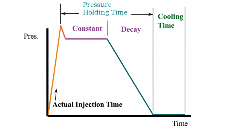
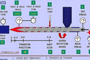
Enjeksiyon kalıplama makinesi dolum süresi, vida hareketinden boşluğun tamamen dolmasına kadar geçen dolum fazı süresidir. Paketleme ve tutma süresini içermez, bu nedenle mühendisler ilk hız profilini ayarlamak, kayma ısısını tahmin etmek ve makine kapasitesini kalıp hacmiyle karşılaştırmak için kullanır.
Üretim ortamında “dolum süresi” terimi bazen toplam enjeksiyon süresi ile karıştırılır. Bunlar aynı şey değildir. Makine zamanlayıcısındaki toplam enjeksiyon süresi dolum artı paketlemeyi içerir; V/Q formülü yalnızca dolum aşaması için geçerlidir. Bu ikisini birbirine karıştırmak, mühendislerin yeni bir kalıp kurarken yaptığı en yaygın hatalardan biridir.
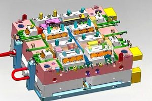
Bu enjeksiyon kalıbı geometry — runner layout, gate type, wall thickness distribution — dictates how the melt front advances. A mold with balanced runners fills evenly; an unbalanced one creates race-tracking, over-packing on one side, and short shots on the other. That is why mold design and fill-time calculation are inseparable.
Why Does Filling Time Matter for Product Quality?
Dolum süresi önemlidir çünkü eriyik sıcaklığını, basınç transferini, kaynak çizgilerini, kısa dolumları, taşmaları ve döngü süresini kontrol eder. Çok yavaş bir dolum, akış cephesini boşluk dolmadan dondurabilirken, çok hızlı bir dolum malzemeyi aşırı kaymaya maruz bırakabilir veya ayırma çizgisinde taşmaya neden olabilir.
Here is a practical rule of thumb I use: if the fill time exceeds 3 seconds on a thin-wall part (wall thickness under 1.5 mm), the probability of a short shot rises above 15 percent. If the fill time is under 0.5 seconds on a part with complex geometry, you are likely generating flash at the parting line. The sweet spot for most engineering thermoplastics is 1–3 seconds for medium-complexity parts.
Parça kalitesinin ötesinde, dolum süresi doğrudan döngü süresini ve üretim kapasitesini etkiler. 16 boşluklu bir kalıpta 12 saniyelik döngüden 0,5 saniye kazanmak, makine başına yıl boyunca yaklaşık 250.000 ek parça anlamına gelir. 47 presin çalıştığı bir fabrika katında, bu yılda 11 milyondan fazla ek parça demektir — önemli bir gelir ve maliyet avantajı.
“Dolum süresi ve paketleme süresi enjeksiyon döngüsünde ayrı aşamalardır.”Doğru
Correct. Filling time covers only the phase when the cavity goes from empty to volumetrically full. Packing time is the subsequent phase where additional material is pushed in to compensate for shrinkage. Most machine timers show injection time as the sum of both.
“Daha uzun bir dolum süresi her zaman daha iyi bir yüzey kalitesi üretir.”Yanlış
Excessively long fill time allows the melt to cool and increase in viscosity, which can cause flow marks, weld lines, and short shots. Optimal surface finish comes from the right fill speed — not the slowest one.
What Factors Affect Filling Time?
Dolum süresini etkileyen ana faktörler malzeme viskozitesi, kalıp geometrisi, enjeksiyon hızı, basınç limiti ve eriyik ile kalıp sıcaklıklarıdır. Malzeme akış davranışı temel çizgiyi belirlerken, yolluk uzunluğu, kapı boyutu, duvar kalınlığı ve makine akış kapasitesi, akış cephesi donmadan önce boşluğun dolup dolamayacağını belirler.
Material Viscosity
Viscosity is the single biggest material factor. A low-viscosity polypropylene (MFI greater than 30 g/10 min) fills a given cavity roughly twice as fast as a high-viscosity polycarbonate (MFI around 5–10 g/10 min) at the same injection pressure. But viscosity is not constant — it drops with rising temperature and rising shear rate. This shear-thinning1 davranışı, doğru tahminler için Newtonyen olmayan modellemenin temel olmasının nedenidir.
Kalıp Geometrisi
Runner length and diameter, gate size, number of cavities, and wall-thickness distribution all create flow resistance. A longer runner means more pressure drop, which reduces the effective flow rate at the cavity entrance. Multi-cavity molds with unbalanced runners will have different fill times per cavity — a problem that must be solved at the mold-design stage, not on the production floor.
Machine Parameters
Enjeksiyon hızı, enjeksiyon basınç limiti, vida çapı ve nozul ucu geometrisi, makinenin sağlayabileceği maksimum hacimsel akış hızı Q'yu belirler. 40 mm vidalı ve 150 mm/s hızında çalışan 200T pres üzerinde, Q yaklaşık pi çarpı 20 kare çarpı 150'dir, bu da yaklaşık 188,5 cm³/s'ye eşittir. Vida 30 mm versiyonla değiştirilirse Q yaklaşık 106 cm³/s'ye düşer — aynı boşluk için dolum süresini anında yaklaşık artırır.
Melt and Mold Temperature
Higher melt temperature reduces viscosity, speeding up the fill. Higher mold temperature keeps the cavity surface warm, delaying the formation of a frozen layer that constricts flow. Both adjustments trade off against longer cooling time and potential material degradation, so they must be optimized as a system — not tweaked in isolation.
How Do You Calculate Filling Time?
There are four main methods, each trading simplicity for accuracy. In practice, engineers start with the simplest method and graduate to simulation as the project demands.
Method 1 — Empirical Formula (tf = V / Q)
En yaygın kullanılan hızlı tahmin, hacimsel orandır. Boşluk hacmi V (cm³) makinenin hacimsel akış hızı Q (cm³/s) ile bölünürse dolum süresi saniye cinsinden bulunur. Akış hızı, vida kesit alanı A ve vida enjeksiyon hızı v'den hesaplanır. Formül olarak: Q, A çarpı v'ye eşittir, bu da pi çarpı (D bölü 2) kare çarpı v'ye eşittir. Ardından tf, V bölü Q'ya eşittir.
Çalışılmış örnek — 100 mm/s'de 30 mm vidalı PP muhafaza, boşluk hacmi 200 cm. Vida alanı A, pi çarpı 15 kareye eşittir, bu da 706.86 mm² verir. Akış hızı Q, 706.86 mm² çarpı 100 mm/s'ye eşittir, bu da 70,686 mm/s veya yaklaşık 70.69 cm/s'dir. Boşluk hacmi 200 cm'yi 70.69 cm/s'ye bölmek, yaklaşık 2.83 saniyelik bir dolum süresi verir.
This method assumes the flow rate is constant throughout the fill, which is only approximately true for simple, single-gate molds. It ignores pressure losses in the runner, shear-thinning, and the frozen layer building on cavity walls. Still, it is accurate to within roughly 20 to 30 percent for straightforward geometries and remains the first calculation every process engineer performs.
Method 2 — Newtonian Fluid Model
For Newtonian fluids, viscosity is constant regardless of shear rate. Under this assumption, you can use the Hagen-Poiseuille equation2 bilinen boyutlardaki kanallardan akış için ve her bir dağıtıcı bölümündeki basınç düşüşünü hesaplayın, ardından mevcut enjeksiyon basıncından Q'yu türetin. Pratikte, çok az termoplastik kalıp dolumu sırasında gerçek Newton akışkanı gibi davranır — çoğu kayma inceltici psödoplastik malzemedir. Newton modeli öncelikle bir öğretim aracı ve simülasyon çıktıları üzerinde bir sağduyu kontrolü olarak kullanışlıdır.
Method 3 — Non-Newtonian (Power-Law) Model
Bu power-law model3 kayma gerilimi ile kayma hızı arasındaki ilişkiyi iki parametreyle — kıvam indeksi k ve akış davranış indeksi n — tanımlar. Çoğu termoplastik için n, 1'den küçüktür, bu da kayma inceltici davranış anlamına gelir. Tipik bir PP, işleme sıcaklıklarında n yaklaşık 0,3 ila 0,4 değerine sahip olabilir. Güç yasası modeli, gerçek kalıplama koşullarında Q için daha iyi bir tahmin sağlar çünkü kapı yakınındaki yüksek kayma hızlarında viskozite azalmasını hesaba katar.
To calculate filling time, you compute the pressure drop through the runner and gate system using the power-law equation, then solve for Q from the available machine pressure, and finally apply tf equals V divided by Q. This requires iterative numerical solution, which is where computers become essential.
“Çoğu termoplastik kayma incelticidir, yani kayma hızı arttıkça viskozite azalır.”Doğru
Correct. Under the power-law model, most thermoplastics have a flow behavior index n less than 1, so effective viscosity drops at higher shear rates. This is why injection speed has a non-linear effect on fill time and why faster injection can fill cavities more efficiently than a simple linear model would predict.
“Ampirik V/Q formülü, besleyici sistemindeki basınç kaybını hesaba katar.”Yanlış
The simple tf equals V divided by Q formula assumes constant flow rate and ignores runner pressure drop, shear-thinning, and frozen layer build-up. It is a first approximation only.
Çoğu orta karmaşıklıktaki termoplastik parçalar, tipik üretim ekipmanlarında standart işleme koşullarında 1 ila 3 saniye içinde doldurulur. İnce duvarlı ambalaj kalıpları 0,5 saniyenin altında dolabilirken, kalın duvarlı büyük yapısal parçaların tamamen dolması 5 ila 10 saniye sürebilir. Kesin aralık, boşluk hacmine, malzeme viskozitesine, duvar kalınlığına ve enjeksiyon kalıplama makinesinin maksimum akış hızı kapasitesine bağlıdır. Yeni bir kalıp projesi için işlem parametrelerini hassas ayarlamadan önce, gerçekçi bir temel oluşturmak için kendi üretim geçmişinizdeki benzer kalıplarla karşılaştırma yapın.
Modern CAE araçları, malzemenin gerçek reolojik verilerini (genellikle reçine üreticisi tarafından sağlanır) kullanarak kalıp geometrisinin 3B ağı üzerinde tam momentum, enerji ve süreklilik denklemlerini çözer. İş akışı şöyledir: CAD'i içe aktar, modeli ağla, malzeme verilerini ata, proses koşullarını ayarla, çözücüyü çalıştır, ardından sonuçları analiz et.
Simulation accuracy for filling time is typically within 3 to 8 percent compared to measured values — a dramatic improvement over the 20 to 30 percent margin of the empirical formula. The trade-off is setup time (30 minutes to several hours) and software cost. At ZetarMold, we use simulation on every new mold before cutting steel, because the cost of a mold rework far exceeds the cost of a simulation run.
For the PP housing example above, Moldflow predicted a fill time of 2.85 seconds — within 0.7 percent of the measured 2.83 seconds. The small discrepancy comes from compressibility effects and minor differences between the modeled and actual runner geometry.
“Profillenmiş enjeksiyon hızı, dolum süresini azaltırken aynı zamanda hata oranlarını da düşürebilir.”Doğru
By starting slow through the gate (preventing jetting), speeding up in the cavity, and decelerating near end-of-fill (allowing air evacuation), profiled injection achieves the best of both worlds — shorter fill and fewer defects. Most modern machines support 5 to 10 velocity stages.
“İkinci bir kapı eklemek her zaman parça kalitesini iyileştirir.”Yanlış
A second gate reduces fill time but introduces a weld line where the two melt fronts meet. If the weld line falls on a structural or cosmetic surface, the part may be weaker or visually defective. Gate placement must be optimized holistically using simulation to predict weld-line location.
How Do All Calculation Methods Compare?
Hesaplama yöntemleri ampirik V/Q, Newton akışı, güç yasası akışı ve sayısal simülasyondur. Basit V/Q yöntemi erken tahminler için yeterince hızlıyken, Moldflow veya Moldex3D ince duvarlı, çoklu geçitli veya yüksek riskli üretim kalıpları için en iyi tahmini verir.
| Method | Calculated Fill Time | Accuracy vs. Measured | Setup Effort |
|---|---|---|---|
| Empirical (V/Q) | 2.83 s | baseline | 1 minute |
| Newtonian model | 2.83 s | same assumptions | 10 minutes |
| Power-law model | 2.78 s | approximately minus 1.8% | 30 minutes |
| Moldflow simulation | 2.85 s | plus 0.7% | 1 to 2 hours |
| Measured (trial shot) | 2.80 s | actual | 2 to 4 hours |
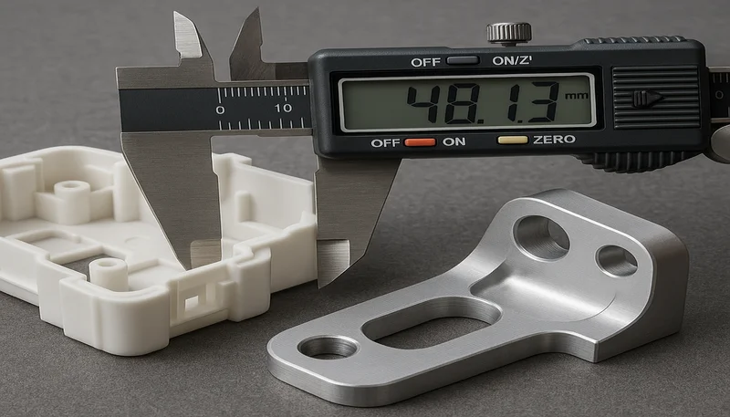
Bu nispeten basit tek kapılı parça için, tüm yöntemlar %2 içinde uyuşur. Farklar, çok kapılı, ince cidarlı veya insert kalıplı parçalarda çok daha büyük olur — tam da simülasyonun fayda sağladığı durumlar. Sıkı toleranslı parçalarda (CNC işlenmiş kalıplar ±0,05 mm tutuyorsa), 0,2 saniyelik bir dolum süresi hatası bile boyutları spesifikasyon dışına itebilir, bu nedenle çoğu yüksek hassasiyetli kalıpçı, tam üretim öncesinde hesaplamayı kısa dolum çalışmasıyla doğrular.
How Can You Optimize Filling Time?
Calculating fill time is only the beginning. Optimizing it — reducing cycle time while maintaining or improving part quality — is where the real engineering value lies. Here are the levers we pull most often on the production floor.
Increase Injection Speed
Raising the screw velocity from 100 mm/s to 150 mm/s in our example drops fill time from 2.83 s to about 1.89 s. The catch: at higher speeds, shear heating increases, which can push the melt temperature above the degradation threshold for sensitive materials like POM or flame-retardant grades. Always monitor melt temperature with a pyrometer after speed changes.
Optimize Runner and Gate Design
Adding a second gate to our example mold reduced simulated fill time from 2.85 s to 1.75 s — a 39 percent improvement. Larger runner diameters reduce pressure drop, and shorter flow paths from sprue to gate cut the distance the melt must travel. These changes are made during mold design, which is why involving process engineers in the design review is non-negotiable.
Raise Melt Temperature Within Limits
Increasing melt temperature from 220 degrees C to 240 degrees C for PP can reduce viscosity by 20 to 30 percent, shortening fill time proportionally. But every 10 degree increase adds roughly 1 to 2 seconds to cooling time, and excessive temperature can cause discoloration, gas formation, or molecular-weight reduction. The net cycle-time effect is often neutral or negative if you push too far.
Use Profiled Injection Speed
Rather than running at a single speed, modern machines allow multi-stage velocity profiles — slow through the gate to prevent jetting, then fast through the cavity, then slow again near the end of fill to prevent flash and allow air to escape. Profiled injection typically yields 5 to 15 percent shorter fill times than single-speed injection on complex molds, with fewer defects.
What Does Real-World Production Teach Us About Filling Time?
Gerçek dünya üretimi, dolum süresinin kısa dolum çalışmaları, boşluk denge kontrolleri ve parça incelemesiyle doğrulanması gereken bir tahmin olduğunu gösterir. Şanghay tesisimizde, V/Q tahminiyle başlar, dolum desenini doğrular ve ardından hız profillerini hatalara, döngü süresine ve boyutsal stabiliteye karşı ayarlarız.
Gerçek dünya üretimi, dolum süresinin kısa dolum çalışmaları, boşluk denge kontrolleri ve parçaların incelenmesiyle doğrulanan bir tahmin olduğunu öğretir. Şanghay tesisimizde, başlangıç enjeksiyon hızını ayarlamak için V/Q tahminiyle başlar, ardından hız profillerini hatalara, döngü süresine ve boyutsal stabiliteye karşı ayarlamadan önce kısa dolum çalışmaları yürütürüz.
One lesson that took years to internalize: the fastest fill time is rarely the best fill time. On a multi-cavity mold for automotive connectors, we found that running at 85 percent of maximum injection speed actually yielded lower scrap than running flat-out, because the slightly slower fill gave the vents enough time to evacuate air. The 0.3 seconds we added to fill time saved 12 percent in scrap — a far larger cost saving than the tiny throughput reduction.
Enjeksiyon kalıplı parçalar tedarik ediyorsanız ve sadece makine hızını artırmak yerine dolum süresini bilimsel olarak optimize eden bir tedarikçi arıyorsanız, üretim ortaklarını değerlendirmek için çerçevemize göz atmak üzere enjeksiyon kalıplama tedarikçi tedarik rehberimize bakın.

Frequently Asked Questions About Filling Time
What is a normal filling time for injection molding?
Most medium-complexity thermoplastic parts fill in 1 to 3 seconds under standard processing conditions on typical production equipment. Thin-wall packaging molds may fill in under 0.5 seconds, while large structural parts with thick walls can take 5 to 10 seconds to fill completely. The exact range depends on cavity volume, material viscosity, wall thickness, and the injection molding machine maximum flow rate capability. Always benchmark against similar molds in your own production history to establish a realistic baseline before fine-tuning process parameters for a new mold project.
power-law akışkan modeli, kayma gerilimini kayma hızına τ = k × γ̇ⁿ denklemiyle ilişkilendiren power-law veya Ostwald-de Waele modelini ifade eder; burada k tutarlılık indeksi ve n akış davranış indeksidir.
Most modern injection molding machines display fill time directly on the controller screen, making it easy to read during initial setup and subsequent process optimization runs. You can also observe the transition from injection pressure to holding pressure on the pressure-versus-time graph, where the inflection point clearly marks the end of the fill phase. For older machines without digital readouts, a stopwatch from screw start to the pressure switchover click gives a reasonable approximation of the actual fill duration in seconds.
Does filling time change with different plastics?
Yes, filling time changes significantly with different plastics due to their varying melt viscosities and thermal properties during the molding process. Low-viscosity materials like polypropylene with an MFI above 20 fill faster than high-viscosity materials like polycarbonate or PEEK, even at the same injection pressure setting on the machine. The material shear-thinning behavior also plays an important role in practice — some polymers thin dramatically under high shear rates, which effectively speeds up cavity filling compared to what a constant-viscosity calculation would predict.
Can filling time be too short?
Absolutely, filling time can definitely be too short for the specific part and mold design at hand. Extremely fast fills cause excessive shear heating, air traps, jetting through the gate, and flash at the parting line of the mold. On transparent parts, jetting creates visible worm-like cosmetic defects on the surface; on structural parts, trapped air causes internal burns and mechanically weak spots. The optimal fill time balances speed with part quality and dimensional consistency — it is not always the minimum possible time your machine can achieve.
What happens if filling time is too long?
When filling time is too long, the melt cools progressively and thickens as it flows through the cavity, increasing the risk of short shots, surface flow marks, and high residual stress in the finished part. Thin-wall parts are especially sensitive to this particular problem — if the frozen layer closes off the flow channel before the cavity is completely full, you get an incomplete part. Long fill times also reduce overall production throughput by extending the injection phase of the molding cycle unnecessarily.
Is Moldflow simulation worth the cost for small molds?
For simple single-cavity molds with straightforward geometry, the basic V/Q formula is usually sufficient for initial setup and saves the simulation fee entirely. For multi-cavity, thin-wall, or high-precision molds, simulation pays for itself by preventing even a single mold revision, which typically costs 10 to 50 times the combined simulation software and engineering time fee. As a practical guideline, any mold with more than two cavities or a flow-length-to-thickness ratio above 100 should definitely be simulated before the mold tool is cut.
How does wall thickness affect filling time?
Thinner walls restrict polymer flow and increase viscous resistance in the mold cavity, requiring higher injection pressure and often resulting in longer overall fill times for the part. The flow length-to-thickness ratio is a key metric for judging fillability of a design — ratios above 150 typically require very high injection speeds to fill completely without short shots. Product designers should aim for uniform wall thickness throughout the part geometry to avoid flow hesitations that cause air traps, weld-line visibility issues, and uneven fill patterns.
What is the difference between fill time and cycle time?
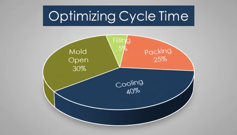
Fill time is just the cavity-filling phase, typically lasting 1 to 3 seconds depending on part size, material choice, and mold complexity. Cycle time includes the complete sequence of filling, packing, cooling, mold opening, ejection, and mold closing — usually 10 to 60 seconds total for a complete production molding cycle. Fill time is typically only 5 to 15 percent of the total cycle. Reducing fill time alone may not significantly reduce overall cycle time if cooling is the dominant bottleneck in the process.
Sonuç
Filling time sits at the intersection of material science, mold engineering, and machine capability. The simplest calculation — tf equals V divided by Q — gives you a useful starting point. Adding rheological modeling or full simulation progressively improves accuracy. And real-world trial shots remain the ultimate validation.
Optimizing fill time is not about chasing the fastest possible number. It is about finding the speed that delivers dimensionally stable, cosmetically clean parts at the lowest total cost — accounting for cycle time, scrap rate, and tooling longevity. That balance is exactly what our engineering team at ZetarMold works toward on every project.
Need help optimizing your injection molding process? ZetarMold’ın mühendislik ekibi, DFM geri bildirimi, kalıp akış simülasyonu ve üretim süreci optimizasyonu sağlar. 400+ malzeme ve 47 makine (90T–1850T) üzerinde 20+ yıllık deneyimle, dolum süresini — ve diğer tüm parametreleri — doğru ayarlamanıza yardımcı olabiliriz. Hemen ücretsiz teklif isteyin.
-
shear-thinning: Kayma incelmesi, bir akışkanın viskozitesinin uygulanan kayma hızı arttıkça azalması olgusunu ifade eder. Çoğu termoplastik eriyik, enjeksiyon kalıplama sırasında bu davranışı sergiler. ↩
-
Hagen-Poiseuille equation: The Hagen-Poiseuille equation describes laminar flow of a Newtonian fluid through a long cylindrical pipe, relating flow rate to pressure drop, pipe radius, and fluid viscosity. ↩
-
power-law model: power-law fluid model refers to the power-law or Ostwald-de Waele model relates shear stress to shear rate with the equation τ = k × γ̇ⁿ, where k is the consistency index and n is the flow behavior index. ↩



 EN
EN  ES
ES  FR
FR  DE
DE  PT
PT  AR
AR  RU
RU  JA
JA  KO
KO  IT
IT  NL
NL  TR
TR  PL
PL 