 Перейти к содержанию

Основные выводы
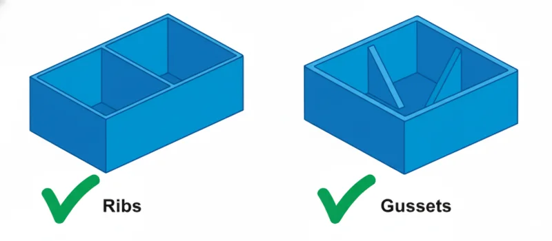
Ribs are thin, wall-like features projecting from the nominal wall of a plastic part, designed to add stiffness and strength without increasing overall wall thickness. By allowing engineers to “core out” thick sections, ribs significantly reduce material usage and part weight. When designed correctly (typically 40–60% of the nominal wall thickness), they prevent defects like sink marks and shorten cooling cycles, thereby optimizing the injection molding process for both cost and performance.
What Is the Definition of Ribs in Injection Molding?
В контексте Литье под давлением, a Ребро is a functional design feature used to reinforce structural integrity. Rather than increasing the thickness of the entire part to achieve stiffness—which increases weight, material cost, and cycle time—engineers utilize ribs to increase the part’s bending stiffness (Moment of Inertia) while maintaining a uniform, thin wall.
Ribs are essential for Lightweighting, a critical objective in automotive and aerospace industries. They allow for the replacement of metal components with Термопласты like Polyamide 66 (PA66) или Поликарбонат (PC) by compensating for the lower modulus of elasticity of plastics through geometric design.
Rib structures allow for significant weight reduction by maintaining structural stiffness without thickening the entire part wall.Правда
Ribs increase the area moment of inertia, providing strength comparable to thicker walls while using less material and reducing cooling time.
Ribs should be designed with the same thickness as the main wall to maximize part strength.Ложь
Ribs must be thinner (typically 40-60% of the wall) to prevent sink marks and voids caused by uneven cooling and volumetric shrinkage.
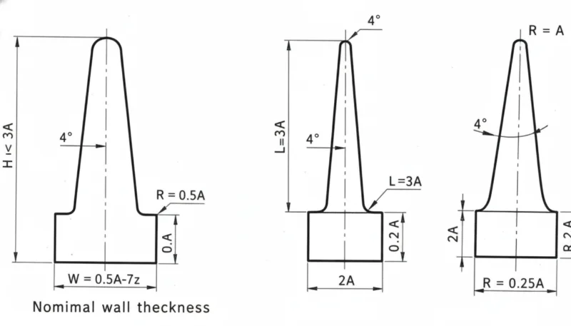
What Are the Key Design Parameters for Ribs?
To maximize weight reduction without inducing cosmetic or structural failures, adherence to specific industry standards (such as DFM or Design for Manufacturing guidelines) is required.
| Параметр | Рекомендуемое значение / диапазон | Ключевые заметки |
|---|---|---|
| Толщина ребра (w) | 40% – 60% of Nominal Wall (t) | Exceeding 60% significantly increases the risk of следы от раковины1 на видимой поверхности (сторона A). |
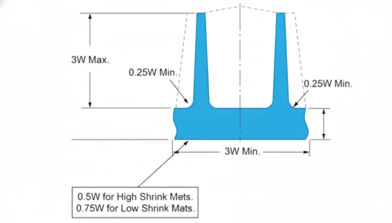
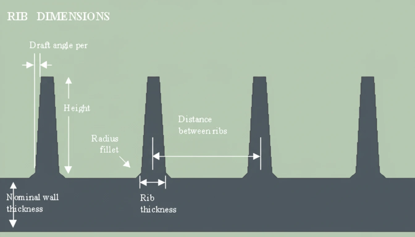
| Высота ребра (h) | ≤ 3.0 × Nominal Wall (t) | Excessive height requires high draft angles and causes mold filling difficulties (gas traps). |
| Угол наклона | 0.5° – 1.5° per side | Essential for ejection; deeper ribs require larger draft angles to prevent drag marks. |
| Радиус основания (филе) | 0.25 × Nominal Wall (t) | Reduces stress concentrations at the rib base; too large a radius mimics a thick wall, causing sinks. |
| Spacing (s) | ≥ 2.0 × Nominal Wall (t) | Ensures adequate steel condition in the mold for cooling channels and structural durability. |
| Equivalent Stiffness | Replaces solid walls ≥ 150% thickness | A ribbed thin wall can match the stiffness of a solid wall 50% thicker, saving ~30% weight. |
What Are the Advantages and Disadvantages of Using Ribs?
| Характеристика | Преимущества | Недостатки |
|---|---|---|
| Снижение веса | Significantly lowers raw material consumption (e.g., Акрилонитрил-бутадиен-стирол (ABS) usage). | Reduces the overall mass, which may affect the perceived quality (heft) of consumer goods if not managed. |
| Время цикла | Thinner walls cool faster; replacing a thick section with ribs reduces the critical cooling path. | Complex rib patterns increase mold surface area, potentially requiring more ejection force. |
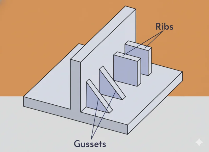
| Structural Integrity | Increases stiffness-to-weight ratio and load-bearing capacity. | Poor design leads to stress concentrators, making parts brittle under impact. |
| Flow Dynamics | Can act as internal flow runners to assist material distribution. | Disrupted flow fronts can cause weld lines or air traps in deep rib sections. |
Adding base radii (fillets) to ribs reduces stress concentration and improves the fatigue life of the part.Правда
Sharp corners act as stress risers; a radius disperses mechanical stress and improves flow during molding.
Adding more ribs always results in a stronger and better plastic part.Ложь
Excessive ribbing can lead to mold filling issues, gas traps, and increased internal stress, potentially causing warpage.
Where Are Ribs Most Commonly Applied?
Ribs are ubiquitous in industries prioritizing Strength-to-Weight ratios:
- Automotive Components:
- Used in bumper fascias, instrument panels, and door trims utilizing Полипропилен (PP).
- Цель: Meet CAFE (Corporate Average Fuel Economy) standards by reducing vehicle weight.
- Потребительская электроника:
- Laptop chassis and smartphone internal frames made of Деформация — это искажение, при котором деталь отклоняется от заданной формы; правильно сбалансированные ребра помогают снизить внутреннее напряжение..
- Цель: Provide rigidity to protect internal PCBs without adding bulk.
- Power Tool Housings:
- Drill shells and battery casings using Glass-Filled Nylon (PA6-GF30).
- Цель: Resist high impact and vibration while maintaining a lightweight ergonomic design.
- Industrial Containers:
- Crates and pallets.
- Цель: Prevent buckling under heavy stacking loads.
How Should Engineers Implement Ribs for Weight Reduction (Step-by-Step)?
To successfully replace solid sections with ribs, follow this engineering workflow:
- Identify Structural Requirements:
Determine the load path and required bending stiffness. Use Анализ методом конечных элементов (FEA)2 to simulate stress. - Determine Nominal Wall Thickness:
Select the minimum wall thickness required for mold filling based on the material’s Melt Flow Index (MFI). - Calculate Rib Thickness:
Apply the 0.6 × t rule. If the material is high-gloss (e.g., PC), reduce to 0.4 × t to avoid cosmetic defects. - Design Rib Geometry:
- Set height limits (<3t).
- Apply draft angles (1° typical).
- Add base radii (0.25t).
- Optimize Spacing (Coring Out):
Remove material from thick sections and replace with a grid or cross-hatch rib pattern. Ensure spacing allows for proper mold cooling. - Analyze for Warpage:
Ribs can cause non-uniform shrinkage. Ensure ribs are oriented in the direction of flow where possible, or use a balanced pattern to minimize деформация3. - Tooling Validation:
Verify that the mold design includes adequate venting for the deep rib cavities to prevent diesel effect (burning).
What Are the Frequently Asked Questions (FAQ)?
Q1: Can ribs eliminate the need for thicker walls entirely?
Yes, in most bending load scenarios. By increasing the Moment of Inertia geometrically, a ribbed part can match the stiffness of a solid part that is 2–3 times heavier.
Q2: Why do ribs cause sink marks on the opposite side of the part?
Sink marks occur because the intersection of the rib and the wall creates a localized thick mass of material. This area cools slower than the surrounding wall, and as it shrinks, it pulls the surface inward. Keeping ribs under 60% of wall thickness minimizes this.
Q3: What is the best material for ribbed parts requiring high stiffness?
Glass-filled materials, such as Polyamide 66 with 30% Glass Fiber (PA66-GF30), are ideal. The fibers align along the ribs during flow, providing exceptional structural reinforcement.
Q4: How does rib height affect the molding cycle?
While ribs are thin, deep ribs (tall height) increase the surface area contacting the mold. If not properly cooled, heat can build up in the mold steel between ribs, potentially extending the cycle time or causing ejection issues.
Q5: What is the role of "crush ribs"?
Crush ribs are small, specialized ribs designed to deform (crush) when a mating part (like a bearing or shaft) is pressed in. They provide a tight interference fit without requiring tight tolerances on the main hole diameter.
Резюме
Ribs are the cornerstone of efficient plastic part design, enabling substantial reductions in part weight and cycle time without compromising structural integrity. By adhering to critical design rules—specifically the rib-to-wall thickness ratio of 40–60% and appropriate draft angles—manufacturers can avoid defects like sink marks and warpage. As industries move toward sustainability and lightweighting, mastering rib design in injection molding is essential for cost-effective and high-performance manufacturing.
-
Sink marks are depressions on the surface of injection molded parts caused by localized shrinkage at thick sections; understanding their cause is vital for cosmetic quality. ↩
-
Simulation software like Moldflow allows engineers to visualize stress and flow before cutting steel, saving time and tooling costs. ↩
-
Warpage is a distortion where the part creates a shape deviation from the design; properly balanced rib patterns help mitigate this internal stress. ↩


