 Saltar para o conteúdo

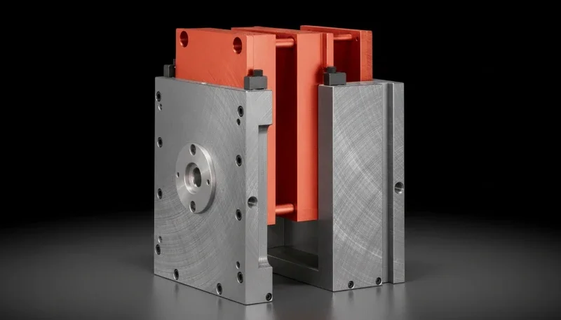
Ferramentas de uso geral, com boa relação custo-benefício
– Sprue diameter typically ranges from 4–8 mm with a 1–3° taper angle, and runner cross-sections are usually 5–12 mm depending on material viscosity.
– Choosing between hot runner and cold runner systems can reduce material waste by 15–30% and cut cycle times by 10–25%.
– Proper sprue and runner design directly impacts part quality, filling balance, and overall production cost in injection molding.
What Is a Sprue in Injection Molding and How Does It Work?
A sprue is the primary channel through which molten plastic travels from the injection molding machine’s nozzle into the mold’s internal runner system. It serves as the single entry point for all material flowing into the mold.
In our factory, we often describe the sprue as the “front door” of the mold. Every gram of plastic that forms your final part must pass through this channel first. The sprue sits inside a sprue bushing1, which is a hardened steel insert that connects the machine nozzle to the mold. The bushing has a precisely machined bore with a tapered interior — typically 1–3° draft angle — that allows the solidified sprue to be pulled out cleanly during ejection.
The sprue performs several critical functions:
- Material delivery: Transfers molten plastic at temperatures of 200–350°C from nozzle to runner system
- Pressure transmission: Maintains injection pressure (typically 500–1500 bar) throughout the filling phase
- Flow guidance: The tapered design minimizes turbulence and ensures smooth material flow
- Desmoldagem: The draft angle and polished surface enable clean separation during part ejection
We’ve found that sprue design mistakes are among the most common issues in new mold projects. An undersized sprue creates excessive pressure drop, while an oversized one wastes material and increases cooling time.
“Sprues and runners are interchangeable terms in injection molding.”Falso
Sprues and runners serve entirely different functions. A sprue is the single vertical entry channel from the nozzle, while runners are the branching horizontal channels that distribute material to multiple cavities.
“Every mold requires a sprue as the primary entry point for molten plastic.”Verdadeiro
Regardless of whether a mold uses a hot runner or cold runner system, there must be a sprue channel that connects the machine nozzle to the internal flow network of the mold.
What Is a Runner in Injection Molding and Why Does It Matter?
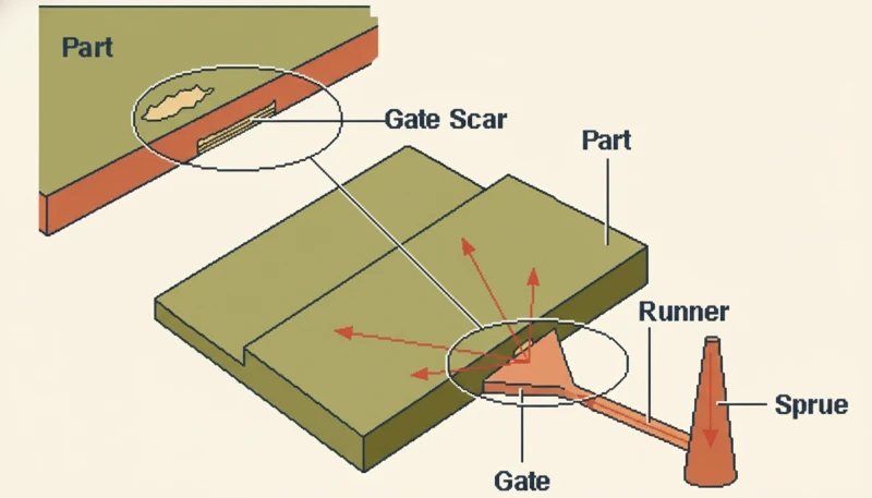
A runner is a channel system within the mold that distributes molten plastic from the sprue to the individual mold cavities through gates. Runners are the “highway network” that ensures each cavity receives the right amount of material at the right pressure.
In our experience working with multi-cavity molds, runner design is where most of the engineering challenge lies. A well-designed runner system must achieve balanced filling — meaning all cavities fill simultaneously and uniformly. This becomes increasingly complex as cavity count rises from 2 to 4, 8, 16, or even 64 cavities.
Runner systems have three main components:
- Primary (main) runner: Connects directly to the sprue, carrying the full volume of material
- Secondary (sub) runners: Branch off the main runner to reach individual cavities or cavity groups
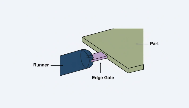
- Gates: The narrow restriction point where plastic enters each cavity, controlling flow rate and allowing clean separation
Common runner cross-section shapes include:
| Cross-Section Shape | Flow Efficiency | Machining Difficulty | Melhor para |
|---|---|---|---|
| Full Round | Highest (100%) | High (requires both mold halves) | High-volume production, engineering resins |
| Trapezoidal | Good (85–90%) | Médio | General purpose, cost-effective tooling |
| Muito liso pode causar aderência | Moderate (70–80%) | Low (single mold half) | Prototype molds, low-volume runs |
| Rectangular | Lowest (60–70%) | Baixa | Not recommended — high pressure drop |
What Are the Key Differences Between Sprue and Runner?
The fundamental difference is that a sprue is a single vertical channel connecting the machine nozzle to the mold interior, while runners are a branching network of horizontal channels distributing material to multiple cavities. They work in sequence — plastic flows through the sprue first, then into the runners, and finally through gates into cavities.
Here is a detailed comparison between sprue and runner in injection molding:
| Caraterística | Tubo | Corredor |
|---|---|---|
| Localização | Between nozzle and runner system | Between sprue and mold cavities |
| Orientação | Typically vertical | Typically horizontal |
| Quantity per mold | Usually one | Multiple branches |
| Shape | Tapered cone (1–3° draft) | Round, trapezoidal, or half-round |
| Typical diameter | 4–8 mm | 5–12 mm |
| Primary function | Deliver material into mold | Distribute material to cavities |
| Material waste | Relatively small volume | Can be significant in cold runner systems |
| Design complexity | Simple — standard bushing | Complex — requires balancing and layout optimization |
In our daily mold design work, we treat the sprue as a standard component — most sprues follow established sizing guidelines based on part weight and material type. Runners, on the other hand, require careful engineering with análise do fluxo do molde2 software to achieve balanced filling across all cavities.
How Does Runner Design Affect Part Quality and Production Cost?
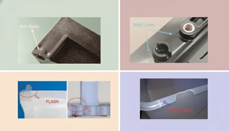
Runner design directly impacts filling balance, cycle time, material waste, and part quality. A poorly designed runner system can cause short shots, uneven filling, weld lines, and increased scrap rates — all of which drive up production costs.
From our factory experience, here are the most critical runner design parameters and their effects:
| Design Parameter | Too Small | Optimal | Too Large |
|---|---|---|---|
| Runner diameter | High pressure drop, short shots | Balanced fill, minimal waste | Long cooling time, excess waste |
| Runner length | Limited cavity layout options | Efficient flow path | Temperature drop, pressure loss |
| Surface finish | N/A | Ra 0.4–0.8 μm | Too smooth can cause sticking |
Consideração Chave
“Larger runners always produce better parts because more material flows through.”Falso
Oversized runners increase material waste, extend cooling time, and can cause sink marks near the gate area. The optimal runner size balances flow efficiency with minimal waste and appropriate cooling time.
“Runner balance is critical for multi-cavity molds to ensure uniform part quality.”Verdadeiro
In multi-cavity molds, unbalanced runners cause some cavities to fill before others, leading to overpacking in early-filling cavities and short shots in late-filling ones. Balanced runner layout ensures all cavities fill simultaneously.
What Is the Difference Between Hot Runner and Cold Runner Systems?
A hot runner system3 keeps the plastic in the runner channels molten using heated manifolds and nozzles, eliminating runner waste entirely. A sistema de canais frios4 allows the plastic in the runners to solidify with each cycle, creating waste material that must be removed and often reground.
This is one of the most important decisions in mold design, and we discuss it with every client during the quoting stage. Here’s how the two systems compare:
| Fator | Corredor quente | Cold Runner |
|---|---|---|
| Mold cost | $5,000–$30,000+ higher | Lower initial investment |
| Material waste | Near zero (no runner scrap) | 15–30% of total shot weight |
| Duração do ciclo | 10–25% shorter | Longer (runner must cool) |
| Color changes | Difficult, time-consuming | Easy and fast |
| Manutenção | Complex, requires specialists | Simple, standard procedures |
| Best for | High-volume, expensive materials | Low-volume, frequent color changes |
In our production facility, we use hot runner systems for about 60% of our high-volume automotive and electronics molds. For medical device components where we need frequent material validation and color changes, we typically recommend cold runner systems with regrind capability.
How Can You Optimize Sprue and Runner Design for Better Results?
Optimizing sprue and runner design involves using simulation software for flow analysis, selecting the right cross-section geometry, implementing balanced runner layouts for multi-cavity molds, and choosing the appropriate runner system type based on production requirements.
Here’s our proven optimization workflow that we follow at Zetar for every new mold project:
- Material analysis: Review the resin’s melt flow index (MFI), recommended processing temperature range, and viscosity data
- Initial sizing: Calculate preliminary sprue and runner dimensions based on part weight, wall thickness, and cavity count
- Flow simulation: Run mold flow analysis to verify fill pattern, pressure distribution, and temperature uniformity
- Balance verification: Ensure all cavities fill within 5% of each other in terms of fill time
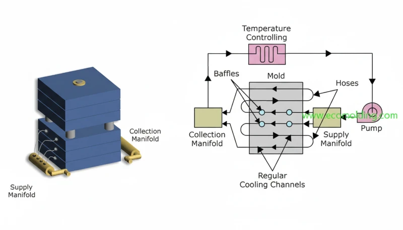
- Cooling optimization: Design cooling channels around sprues and runners to minimize cycle time
- Steel cutting: Machine the mold with optimized dimensions, starting steel-safe (slightly undersized runners)
- Trial and adjustment: Fine-tune during mold trials using actual processing data
We’ve found that investing 2–3 days in proper simulation analysis before steel cutting saves an average of 1–2 weeks of trial-and-error adjustments later — a lesson we learned the hard way on early projects.
What Are Real-World Applications of Sprue and Runner Systems?
Sprue and runner systems are used in every injection molded product, from automotive components and medical devices to consumer electronics housings and packaging. The specific design varies significantly based on the industry’s requirements for precision, volume, and material.
Here are examples from our project portfolio showing how sprue and runner choices differ by application:
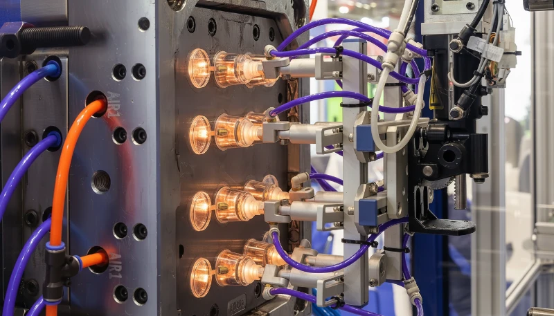
| Indústria | Typical Runner System | Key Consideration | Ferramentas de moldagem por injeção de precisão mostrando canais de alimentação e distribuição |
|---|---|---|---|
| Automóvel | Hot runner, valve-gated | Gate vestige control, high volume | Dashboard trim panels |
| Dispositivos médicos | Cold runner or hot runner | Material traceability, clean room | Syringe barrels |
| Eletrónica de consumo | Hot runner, thermal-gated | Cosmetic surface quality | Phone case housings |
| Embalagem | Hot runner, 48–96 cavity | Maximum throughput, minimal waste | Bottle caps |
| Household goods | Cold runner, 2–4 cavity | Cost-effective tooling | Storage containers |
Perguntas frequentes (FAQ)
What is the main difference between a sprue and a runner in injection molding?
A sprue is the single vertical channel connecting the injection machine nozzle to the mold interior, while runners are horizontal channels that branch out from the sprue to distribute molten plastic to individual mold cavities. The sprue is the entry point; runners are the distribution network.
Can you eliminate the sprue in injection molding?
In hot runner systems with direct gating (sprue gating), the traditional cold sprue can be eliminated because the plastic remains molten all the way to the cavity. However, there is still a flow path from the nozzle — it’s just heated rather than forming a solid waste piece.
How do you calculate the correct runner size for a mold?
Runner size depends on the material’s melt flow index, part weight, wall thickness, and flow length. A common starting formula is: runner diameter = wall thickness × 1.5 + 1.5 mm. For example, a part with 2 mm wall thickness would start with a 4.5 mm runner diameter, then optimize through flow simulation.
What causes runner imbalance in multi-cavity molds?
Runner imbalance occurs when cavities are at different distances from the sprue, runners have unequal cross-sections, or there are differences in flow path geometry. Even in geometrically balanced (H-pattern) runners, shear-induced imbalance can cause the inner cavities to fill differently than outer ones. Solutions include using melt flippers or adjusting individual gate sizes.
How much material waste do runners typically generate?
In cold runner systems, runner waste typically accounts for 15–30% of total shot weight, depending on the number of cavities and runner layout. For a 100-gram total shot, 15–30 grams may be runner scrap. Hot runner systems eliminate this waste almost entirely, making them cost-effective for high-volume production or expensive engineering resins.
What is a sprue puller and why is it important?
A sprue puller is a feature on the ejector side of the mold (usually a reverse taper or Z-pin) that grips the solidified sprue during mold opening, pulling it out of the sprue bushing. Without a properly designed sprue puller, the sprue can stick in the bushing and cause production stoppages.
Should I choose a hot runner or cold runner system for my project?
Choose hot runner when: annual production exceeds 100,000 parts, material cost is high, cycle time reduction is critical, or gate vestige must be minimal. Choose cold runner when: production volume is low to medium, frequent color or material changes are needed, budget is limited, or simple maintenance is preferred.
Resumo
Understanding the difference between sprue and runner is fundamental to successful injection molding. The sprue serves as the single entry channel from machine to mold, while runners form the distribution network delivering material to each cavity. Together with gates, they form the complete feed system that determines part quality, cycle time, and production cost.
At Zetar, with over 20 years of mold-making experience, we’ve optimized thousands of sprue and runner systems across automotive, medical, electronics, and consumer product applications. Whether you need a simple two-cavity cold runner mold or a complex 64-cavity hot runner system, our engineering team uses advanced flow simulation to ensure optimal design before cutting steel.
Ready to optimize your injection molding project? Contact Zetar’s engineering team for a free mold design review and quotation.
-
A sprue bushing is a hardened steel insert installed in the mold’s stationary platen that provides the interface between the injection machine nozzle and the mold’s internal runner system. It features a precision-machined tapered bore for clean material flow and easy sprue removal. ↩
-
Mold flow analysis is a computer simulation technique using software like Moldflow or Moldex3D to predict how molten plastic will fill a mold cavity, identifying potential issues such as air traps, weld lines, and pressure drops before the mold is manufactured. ↩
-
A hot runner system is a heated manifold assembly inside the mold that keeps plastic in a molten state throughout the runner channels, eliminating solidified runner waste and reducing cycle time compared to cold runner systems. ↩
-
A cold runner system uses unheated channels where molten plastic solidifies along with the part during each molding cycle. The solidified runner must be ejected, separated from parts, and is typically reground for reuse. ↩


