 Skip to content

- Plastic molds fall into five main types: single-cavity, multi-cavity, family, hot runner, and cold runner—each suited to different production volumes and part geometries.
- Mold steel grade directly determines lifespan: aluminum prototypes last 5,000–50,000 cycles; P20 pre-hardened steel reaches 500,000 cycles; H13 hardened steel exceeds 1,000,000 cycles.
- Mold cost ranges from $3,000 for a simple single-cavity prototype to over $150,000 for a complex multi-cavity production mold—with steel grade, cavity count, and surface finish as the three biggest cost drivers.
- Every plastic mold requires proper venting (0.02–0.05 mm depth), draft angles (1–3° per side), and uniform wall thickness to prevent defects like flash, short shots, and warpage.
- ZetarMold builds plastic molds in P20, H13, S136, and NAK80 steels, with T1 samples delivered in as fast as 15 days.
What Are Plastic Molds?
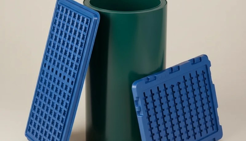
Plastic molds are precision-machined steel or aluminum tools that shape molten thermoplastic or thermoset material into a finished part through the injection molding cycle. Each mold consists of two halves—the cavity (A-side) and core (B-side)—that close under clamping force, receive injected plastic at 150–370°C, and open to eject the cooled part in 15–120 seconds per cycle.
A complete mold assembly includes the cavity and core inserts, the runner system that channels plastic from the machine nozzle to the gate, a cooling circuit to extract heat uniformly, and an ejection system (pins, sleeves, or stripper plates) to release the part. The quality of every dimension, surface finish, and mechanical property in the final plastic part traces directly to how well the mold was designed and built.
Modern plastic molds are built to extremely tight tolerances—cavity dimensions are typically held to ±0.01–0.05 mm—because any deviation is multiplied across every part produced. A well-designed mold running 24/7 at a high-volume facility can produce millions of identical parts over its service life without significant dimensional drift. The mold is not a consumable; it is a capital investment that must be engineered with the same rigor as the part itself.
What Are the Main Types of Plastic Molds?
Five mold configurations cover the vast majority of injection molding applications, each optimized for specific volume, cost, and cycle-time requirements.
| Mold Type | Cavities | Best For | Relative Cost |
|---|---|---|---|
| Single-cavity | 1 | Prototypes, low volume (<10,000 parts/year) | Lowest |
| Multi-cavity | 2–128 | High-volume identical parts (>100,000/year) | Medium–High |
| Family mold | 2–8 (different parts) | Assemblies with multiple components | Medium |
| Hot runner | 1–128 | High volume, zero-waste, fast cycle time | High |
| Cold runner | 1–32 | Flexible material changes, lower upfront cost | Low–Medium |
Single-cavity molds minimize upfront tooling cost and are ideal for prototyping or low-demand parts. Multi-cavity molds—which can run 8, 16, 32, or 64 identical cavities simultaneously—dramatically reduce cost-per-part at volumes above 100,000 units annually. The clamping force and shot size required scale proportionally with cavity count, so the injection machine must be sized accordingly.
Family molds produce two or more different parts in one shot, which suits assembly components that are always used together, such as a housing top and bottom. The trade-off is that an engineering change to any single part puts the entire mold offline. For parts with uncertain design stability, separate single-cavity tools provide far greater flexibility.
Hot runner systems eliminate the cold sprue and runner scrap that cold runner molds generate. By keeping the runner manifold at melt temperature, hot runner molds reduce material waste by 15–30% per cycle and typically cut cycle time by 10–20%. The tradeoff is a higher mold cost—manifold components add $8,000–$30,000 to the tooling bill—and more complex maintenance. Cold runner molds are still preferred when material changes are frequent, when regrind is acceptable, or when the production volume does not justify the hot runner premium.
What Materials Are Plastic Molds Made From?
mold steel4 grade is the single most important factor in determining how many cycles a mold will produce before requiring repair or replacement. The four most common materials span a 20× range in both cost and lifespan.
| Material | Hardness | Expected Cycles | Best Application |
|---|---|---|---|
| Aluminum 7075/6061 | 60–80 HB | 5,000–50,000 | Prototype, bridge tooling |
| P20 pre-hardened steel | 28–32 HRC | 300,000–500,000 | Standard production molds |
| H13 tool steel (hardened) | 48–52 HRC | 1,000,000+ | High-volume, abrasive materials |
| S136 stainless steel | 50–54 HRC | 1,000,000+ | Corrosive resins (PVC, flame retardants) |
| NAK80 pre-hardened | 37–43 HRC | 500,000–800,000 | High-polish optical or cosmetic parts |
Aluminum molds are machined in 5–10 days versus 3–6 weeks for hardened steel, making them the standard choice for pre-production validation and low-volume runs. P20 is the workhorse of the industry: it machines easily before heat treatment, takes a good polish, and delivers a reliable 300,000–500,000 cycle service life at a fraction of H13’s cost. The majority of consumer product molds worldwide run in P20 because the volume and resin combination—typically unfilled PP, ABS, or PE—does not justify upgrading to a harder steel.
H13 and S136 require post-machining vacuum heat treatment and more intensive EDM finishing, which adds cost and lead time. For glass-filled, mineral-filled, or flame-retardant materials that aggressively wear cavity surfaces, the investment pays back through reduced maintenance frequency and longer mold life. NAK80 is the preferred choice for consumer-product molds that demand mirror-finish surfaces (Ra ≤ 0.025 μm) because it polishes to optical quality without additional surface treatment. Selecting the wrong steel grade for a given resin-volume combination is one of the most common and costly mold specification errors.
How Is a Plastic Mold Designed?
Plastic mold design begins with a DFM3 review of the part—checking wall thickness uniformity, draft angles, undercuts, and gate location—before any steel is cut. Skipping this step is the single most common cause of costly mold revisions and delayed production launches. A DFM review typically costs $200–$800 and can identify issues that would otherwise require $5,000–$30,000 in mold rework after first trials.
The six critical design decisions every mold engineer must resolve are: (1) parting line location that minimizes flash risk and simplifies ejection; (2) gate type and position—typically edge, submarine, or hot tip—chosen to avoid visible gate marks on cosmetic surfaces; (3) runner balance for multi-cavity tools so all cavities fill simultaneously; (4) cooling layout with channels 10–15 mm from cavity walls for uniform heat extraction; (5) ejection system sized to release the part without distortion; and (6) venting, with 0.02–0.05 mm deep vents every 25–50 mm around the parting line to prevent burn marks and short shots.
Wall thickness is a frequently underestimated design constraint. Walls thicker than 4 mm create sink marks on the opposite surface as plastic cools and shrinks. Walls thinner than 0.8 mm risk short shots because the melt front freezes before filling the cavity. The optimal range for most engineering resins is 1.5–3.5 mm, with transitions between thick and thin walls tapered at no more than a 3:1 ratio to prevent stress concentrations and knit line weakness.
“Uniform wall thickness reduces warpage and cycle time in plastic molds.”True
Walls thicker than 3–4 mm create localized hot spots that increase cooling time and cause differential shrinkage. Maintaining consistent wall thickness (typically 1.5–4 mm) across a part allows the cooling circuit to extract heat evenly, minimizing warp deflection and keeping cycle times at their minimum value for that part geometry.
“Any steel grade can be used for any plastic material without affecting mold life.”False
Abrasive materials—glass-filled nylon, mineral-filled PP, and flame-retardant compounds—wear P20 cavities 3–5× faster than unfilled resins. Using P20 for a glass-filled PA66 part running at 200,000+ cycles per year results in visible cavity wear within 18–24 months, requiring re-texturing or full insert replacement. Matching H13 or hardened S136 to abrasive materials is essential to achieving cost-effective mold life.
Mold flow simulation (CAE analysis) is strongly recommended before finalizing the design. Running a fill, pack, cooling, and warpage simulation takes 1–3 days and can identify weld line locations, air trap risks, and excessive clamp force requirements—each of which is far cheaper to fix in software than after the mold is cut. Studies across production molds show that pre-build simulation reduces first-shot revision rounds by 40–60% and shortens total time-to-production by 2–4 weeks on average.
Undercuts—features that prevent the part from ejecting straight along the mold-open direction—must be resolved through side actions (sliding cores), lifters, or collapsible cores. Each undercut-resolving mechanism adds $500–$5,000 to mold cost and introduces a moving component that requires maintenance. Redesigning the part to eliminate undercuts through creative parting line placement or design simplification is always the first option to evaluate before committing to complex slide mechanisms.
How Much Do Plastic Molds Cost?
Plastic mold cost ranges from $3,000 for a simple single-cavity aluminum prototype to over $150,000 for a complex multi-cavity hardened-steel production tool—a 50× spread driven primarily by steel grade, number of cavities, and part complexity.

| Mold Type | Steel | Cavities | Estimated Cost (USD) |
|---|---|---|---|
| Simple prototype | Aluminum | 1 | $3,000–$8,000 |
| Standard production | P20 | 1 | $8,000–$25,000 |
| Multi-cavity production | P20/H13 | 4–8 | $20,000–$60,000 |
| High-volume hot runner | H13 | 16–32 | $50,000–$150,000 |
| Complex family mold | H13/S136 | 4–8 (diff. parts) | $30,000–$80,000 |
Beyond the upfront tooling investment, total cost of ownership includes maintenance (typically $500–$3,000 per 100,000 cycles), engineering changes ($1,000–$15,000 each), and eventual end-of-life replacement. High-volume buyers who run a mold 24/7 should model the full lifecycle cost—not just the purchase price—when comparing quotes. A $15,000 P20 single-cavity mold requiring three major repairs over five years may cost more over its lifetime than a $25,000 H13 mold that runs maintenance-free for the same period.
Lead time is closely tied to cost. Aluminum prototype molds deliver T1 samples in 10–15 days. P20 single-cavity molds take 3–4 weeks. Complex multi-cavity H13 tools typically require 6–10 weeks. Requesting a faster turnaround usually adds 15–30% to tooling cost due to overtime machining and expedited EDM slots. Providing complete, frozen 3D CAD data and completing the DFM review before purchase order is the single most effective way to maintain quoted lead time.
Geography affects mold price significantly. Chinese toolmakers typically quote 30–60% below European or North American shops for equivalent complexity and steel specification. The tradeoff involves longer shipping times (3–5 weeks by sea freight), potential IP concerns, and limited ability to make on-site adjustments during tryout. Many global manufacturers use China for production tooling while keeping prototype and critical molds onshore to manage these risks.
“Splitting a family mold into separate single-cavity tools increases flexibility for future design changes.”True
When two or more parts are built into one family mold, an engineering change to any single part requires the entire mold to go offline. Separate single-cavity molds can be revised independently, minimizing production interruption. For parts with different design freeze timelines, separate tooling is almost always the lower-risk strategy despite the higher initial investment.
“More mold cavities always reduce cost-per-part.”False
Cavity count reduces cost-per-part only when the production volume is high enough to offset the increased tooling investment. For annual volumes below 50,000 units, a 4-cavity mold’s higher tooling cost and maintenance complexity frequently makes the total cost per part higher than a single-cavity alternative. The breakeven point depends on machine hourly rate, material cost, and annual demand—and should always be calculated before selecting cavity count.
How Are Plastic Molds Manufactured?
Plastic mold manufacturing follows a precise sequence: 3D design and DFM review, steel procurement and mold base machining, CNC rough milling of cavity and core, EDM (electrical discharge machining) of fine details and textures, grinding and fitting, polishing to required surface finish, assembly of all components, and T1 trial sampling.
CNC milling handles the majority of metal removal and produces tolerances of ±0.02–0.05 mm. EDM—both sinker and wire—is used for sharp inside corners, ribs below 1 mm width, and complex contour surfaces that CNC cannot reach. The EDM process erodes material via controlled electrical discharges, achieving tolerances of ±0.005–0.01 mm without cutting forces that would deflect thin features. Sophisticated 5-axis CNC centers have reduced EDM dependency in recent years by accessing previously unreachable cavity angles directly with ball-end mills.
Surface finish is achieved through bench polishing with progressively finer abrasives (from 320 to 3000 grit) or by EDM texturing for matte and leather-grain surfaces. Optical surfaces require diamond paste lapping to achieve Ra ≤ 0.01 μm. The SPI (Society of the Plastics Industry) surface finish classification provides a standard reference: A-1 (super high gloss) through D-3 (rough matte) enables designers and moldmakers to communicate surface requirements unambiguously.
The final step before T1 trials is trial assembly—fitting the mold in the injection machine, checking shut-off surfaces for flash-free closure, and verifying cooling circuit flow rates. A pre-trial checklist should confirm: all cooling circuits are connected and leak-tested, ejector travel is set correctly, mold temperature is at the specified setpoint, and machine tonnage and shot size are within range. Skipping any of these steps risks a failed T1 shot that could damage the mold or part.
T1 evaluation follows a structured process. First-off parts are measured against the part drawing using CMM (coordinate measuring machine) inspection, with all critical dimensions reported in a first article inspection (FAI) report. Dimensional deviations are categorized as: acceptable within tolerance, correctable by process adjustment, or requiring mold modification. Steel-safe design—deliberately leaving cavity dimensions 0.1–0.2 mm undersized on non-draft surfaces—is a best practice that allows the mold to be opened up (removing metal) rather than welded (adding metal, which is harder and less reliable) during dimensional correction.
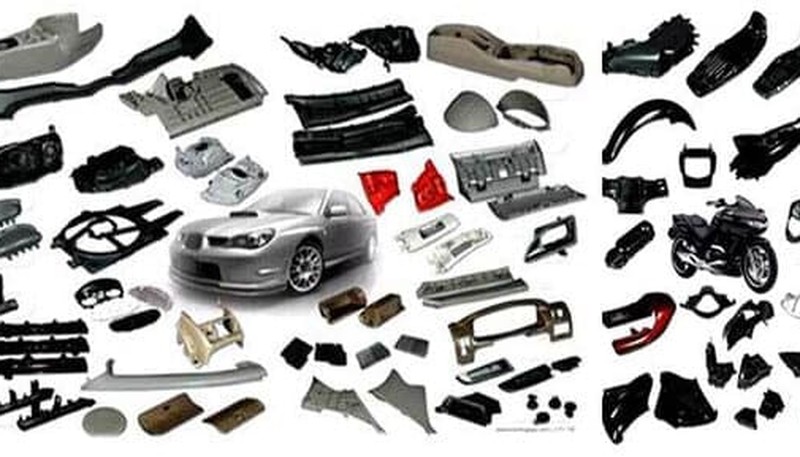
What Are Plastic Molds Used For?
Plastic molds produce virtually every injection-molded component across all major industries. Automotive applications—bumper fascias, interior door panels, dashboard components, and lamp housings—account for approximately 35% of global injection molding output by value. Consumer electronics enclosures, medical device housings, and packaging closures each represent large and growing segments of the total market.
Industrial applications include pump housings, valve bodies, conveyor components, and electrical enclosures where dimensional accuracy and structural performance are critical. Packaging alone consumes more than 40% of all plastic resin produced globally, with high-speed thin-wall molds running at cycle times under 5 seconds for caps, closures, and containers. The design requirements for thin-wall packaging molds—fill speeds above 300 mm/s, injection pressures to 2,000 bar, and cavity tolerances to ±0.01 mm—represent some of the most demanding specifications in the industry.
Consumer electronics is one of the fastest-growing application segments for precision plastic molds. Smartphone housings, laptop bezels, and wearable device enclosures demand SPI A-1 or A-2 surface finishes on cosmetic surfaces, with gate vestige controlled to within 0.1 mm. Achieving these surface standards requires high-polish NAK80 or S136 cavities, carefully designed submarine or hot-tip gates, and precisely balanced cooling to prevent differential shrinkage that would create visible sink marks or waviness.

Advanced applications include multi-material molding—overmolding and insert molding—where a plastic mold is designed to receive a pre-placed metal insert or a previously molded part, bonding two materials in a single production step. These techniques eliminate secondary assembly operations and are widely used in medical devices (metal-to-plastic interfaces), automotive electronics (connector housings with metal terminals), and consumer products (soft-grip handles over rigid cores). Overmolding molds require precise shut-off surfaces where the second material interfaces with the substrate, with tolerances often held to ±0.02 mm to prevent flashing of the overmolded elastomer.
Medical-grade plastic molds demand the highest precision tier: cavity tolerances of ±0.005 mm, S136 corrosion-resistant steel to handle aggressive medical-grade resins (PEI, PEEK, POM), and cleanroom-compliant manufacturing environments. These molds are also subject to FDA validation requirements, including installation qualification (IQ), operational qualification (OQ), and performance qualification (PQ) documentation. A single medical mold project may require 300–500 pages of validation documentation in addition to the physical tool and sample parts.
Aerospace applications push tolerances and material requirements further still. Molds for structural aerospace plastic components must hold cavity dimensions to ±0.003–0.005 mm, use materials with demonstrated traceability, and produce parts that meet AS9100 quality system requirements. The mold cost for these applications routinely exceeds $100,000 for a single-cavity tool because of the precision machining, validation burden, and material certification requirements involved.
The range of plastic materials processed through injection molds spans from commodity resins—polypropylene (PP), polyethylene (PE), ABS, and polystyrene (PS)—to high-performance engineering polymers including PEEK, PEI, PPS, and LCP. Each resin class imposes different requirements on the mold: melt temperature range, shrinkage rate, moisture sensitivity, and corrosiveness all influence steel selection, surface finish, cooling design, and processing window. A mold designed for ABS cannot simply be repurposed for PEEK without mold temperature upgrades (PEEK requires 160–200°C mold temperature versus 40–80°C for ABS) and possibly steel replacement if the cavity was not originally hardened.
Regardless of industry, the economics of plastic molding are defined by the relationship between part volume and tooling cost. Every additional cavity, every side action, every hot runner drop, and every surface finish upgrade adds to the mold investment that must be recovered through production. Understanding this cost structure—and designing both the part and the mold with total lifecycle cost in mind—is the defining skill of an experienced injection molding engineer. Cheap molds that require frequent maintenance or early replacement invariably cost more over a three-to-five year production run than well-specified tools built to match the application’s actual demands.
Selecting a qualified mold supplier requires evaluating machining capability (5-axis CNC, EDM accuracy, CMM metrology), steel sourcing (certified domestic or European steel versus unverified spot-market material), process documentation (DFM reports, mold flow simulation, first article inspection), and after-sales support (modification capability, spare parts, on-site tryout assistance). Price alone is not a reliable proxy for quality; a thorough technical audit of the supplier’s capabilities, combined with reference checks on similar mold complexity, is the most reliable qualification approach.
For global brands sourcing plastic molds in China, the most effective risk mitigation strategy is a clearly written mold specification document covering: steel grade with material certification requirements, required surface finish (SPI classification), dimensional tolerances by feature category, acceptance criteria for first article inspection, delivery milestone schedule with penalty clauses, and IP ownership statements. A comprehensive mold specification reduces ambiguity and creates a contractual baseline that protects both buyer and supplier when disputes arise.
How Do You Maintain Plastic Molds?
Plastic mold maintenance is essential to sustaining part quality and avoiding unplanned downtime—a single mold failure can halt an entire production line for 12–72 hours. Preventive maintenance intervals are based on cycle count: minor service (cleaning, lubrication, vent cleaning) every 25,000–50,000 cycles; full inspection every 100,000–250,000 cycles; and major overhaul (insert replacement, cavity polishing) at 500,000 cycles or when dimensional drift exceeds tolerance.

The most common maintenance tasks are: (1) cleaning vents that clog with polymer degradation byproducts—blocked vents cause burn marks and short shots within days of buildup; (2) re-lubricating ejector pins and sliding cores on a cycle-count schedule to prevent galling and seizure; (3) inspecting and re-stoning parting line surfaces that develop burrs from flash wear; and (4) checking cooling circuit flow rates and inlet/outlet temperature differential—a delta above 10°C between inlet and outlet indicates fouling or blockage in the cooling channel.
Mold storage requires thorough cleaning, coating all steel surfaces with rust inhibitor, and storing the mold in a controlled humidity environment below 60% RH. Molds left in humid conditions without protective coating develop surface rust within weeks, requiring cavity re-polishing before the next production run—a preventable cost that typically runs $500–$3,000 per affected insert. Best practice is to bag the mold in polyethylene after coating and store it in a dedicated racking system where it cannot be damaged by other molds or equipment.
A mold maintenance logbook—recording every service event, cycle count, issue observed, and corrective action taken—is indispensable for managing a fleet of production molds. Without cycle count records, maintenance intervals are guesswork, and the root cause of recurring defects cannot be correlated to specific maintenance events. Modern mold shops implement RFID tags on molds that link to a database tracking cycle count, maintenance history, and location, enabling predictive maintenance rather than reactive repair.
Frequently Asked Questions About Plastic Molds
How long does it take to build a plastic mold?
Lead time depends on complexity and steel grade. Aluminum prototype molds deliver T1 samples in 10–15 days. Single-cavity P20 production molds take 3–4 weeks. Complex multi-cavity H13 tools require 6–10 weeks. Adding hot runner systems extends lead time by 1–2 weeks. Providing complete, frozen 3D CAD data and a finalized DFM review at project start eliminates the most common delays. Late-stage design changes are the single biggest cause of mold delivery overruns—each round of revisions after mold construction begins typically adds 1–2 weeks to the schedule.
What is the minimum order quantity for plastic molds?
There is no minimum order quantity for mold tooling—you can commission a single prototype mold to produce as few as 50 parts. Production justification depends on amortized tooling cost per part: at a $10,000 mold cost, producing 10,000 parts puts $1.00 of tooling cost in every part. Most customers find injection molding becomes cost-competitive with 3D printing or CNC machining above approximately 1,000–5,000 parts per year. For extremely low volumes, bridge tooling in aluminum at $3,000–$8,000 provides production-quality parts while the design stabilizes before committing to full hardened-steel production tooling.
What causes flash defects in plastic molds?
Flash—thin plastic fins that form along the parting line—is caused by insufficient clamping force, worn parting surfaces, excessive injection pressure, or mold plates that have warped out of parallel. The root cause must be isolated before applying a fix: adding clamping tonnage will not help if the issue is a worn parting line. Solutions include increasing clamp force to the calculated minimum (projected area × cavity pressure), re-stoning parting surfaces to restore flat shut-off, reducing injection speed or pack pressure to lower peak cavity pressure, and adding side locks to maintain parting line alignment during injection.
How do I choose between a hot runner and cold runner mold?
Choose a hot runner mold when annual volume exceeds 500,000 parts, material cost is high (engineering resins above $5/kg), or cycle time is critical. Cold runner molds are preferable for colors or materials that change frequently, for small-volume production where runner regrind is acceptable, or when budget constraints make the $8,000–$30,000 hot runner premium impractical. For mid-volume applications, a cold runner with a well-designed balanced runner system often delivers 80% of the efficiency at 30% of the hot runner cost. Always calculate the material savings versus the hot runner investment payback period before specifying.
What draft angle is required for plastic molds?
Draft angle requirements depend on the resin and surface finish. Unfilled resins with smooth polished surfaces require a minimum of 0.5–1° per side. Textured surfaces (leather grain, stipple) require 1.5–3° per 0.025 mm of texture depth—a medium leather grain at 0.1 mm depth requires at least 4° of draft. Fiber-filled or stiff resins need 2–3° minimum to prevent drag marks during ejection. Insufficient draft is one of the most common causes of surface scratches and ejection-force damage on first trial shots. Adding draft at the design stage costs nothing; correcting insufficient draft after mold construction requires cavity welding and remachining, typically costing $1,000–$5,000.
How many parts can a plastic mold produce?
Mold life depends on steel grade and material. Aluminum molds last 5,000–50,000 cycles. P20 molds achieve 300,000–500,000 cycles under normal conditions. H13 hardened molds produce 1,000,000+ cycles reliably. Running abrasive glass-filled or mineral-filled resins reduces life by 40–60% unless an upgraded steel grade is specified upfront. Proper preventive maintenance—cleaning, lubrication, and vent service on a cycle-count schedule—can extend mold life by 20–30% beyond the baseline estimate. Mold life is also affected by injection pressure (higher pressure wears parting surfaces faster), mold temperature (high-temperature resins fatigue steel at accelerated rates), and the corrosiveness of the resin being processed.
What is the difference between a mold and a die in plastic manufacturing?
In plastic manufacturing, ‘mold’ refers to the tooling used in injection molding, blow molding, and compression molding where plastic material is formed by filling an enclosed cavity under pressure. ‘Die’ is used in extrusion to describe the open orifice that gives continuous profiles (pipes, sheets, tubes) their cross-sectional shape. In die casting, ‘die’ describes the equivalent of an injection mold for metal alloys. The two terms are sometimes used interchangeably in informal and regional usage, but mold is the technically correct term for closed-cavity plastic forming tools. In the United Kingdom and Australia, ‘mould’ is the standard spelling.
-
injection mold design: Injection mold design refers to the engineering process of creating the cavity, core, runner system, and cooling channels that shape molten plastic into a finished part. ↩
-
mold flow analysis: Mold flow analysis is a simulation method that predicts how molten plastic fills a mold cavity, identifying potential defects such as weld lines, air traps, and sink marks before tooling is cut. ↩
-
DFM: DFM (Design for Manufacturability) is a design review process that evaluates part geometry, wall thickness, draft angles, and gating strategy to ensure a plastic part can be molded efficiently and defect-free. ↩
-
mold steel: Mold steel refers to specialized tool steels—such as P20, H13, S136, and NAK80—used to machine mold cores and cavities, selected based on required hardness, polishability, and production volume. ↩
-
plastic injection moulding process: The plastic injection moulding process is a manufacturing cycle in which plastic pellets are melted, injected under pressure into a closed mold, cooled, and ejected as a finished part—typically completing one cycle in 15–120 seconds. ↩


