 콘텐츠로 건너뛰기

- Most injection molding defects trace back to the Process-Mold-Material triangle—change one variable at a time.
- Flash usually means clamping force or tooling alignment; sink marks point to packing pressure or thick sections.
- Warpage is driven by differential shrinkage from uneven cooling or fiber orientation.
- Short shots often require venting improvements or injection speed increases.
- Prevention is cheaper than post-processing: design defects out before steel is cut.
What Is the Real Cost of Injection Molding Defects?
The real cost of injection molding defects is defined by the function, constraints, and tradeoffs explained in this section. If you are comparing vendors or planning procurement, our injection molding supplier sourcing guide covers RFQ prep, qualification, and commercial risk checks.
Injection molding defects are expensive because scrap consumes material, press time, labor, and customer trust. In our factory reviews, our engineers start with a 3-part check: process window, mold condition, and material behavior. On a 100,000-part run, even 5.0% scrap means 5,000 parts before rework starts.
Injection molding defects are expensive because scrap consumes material, press time, labor, and customer trust. In our factory reviews, we start with a 3-part check: process window, mold condition, and material behavior. On a 100,000-part run, even 5% scrap means 5,000 bad parts before rework starts.
You just pulled a batch of parts off the press and 18% of them have visible defects. That is not a cosmetic problem—it is money walking out the door. Scrap, rework, delayed shipments, and angry customers all trace back to the same root: something in your process, mold, or material was not dialed in.
에서 사출 성형 industry, understanding injection molding defect classification is one of the most valuable skills an engineer can develop. The classic framework is the Process-Mold-Material triangle: almost every defect has one primary root cause and two contributing factors. The trick is isolating which variable is the culprit before you start turning knobs.
Semi-crystalline polymers like Polypropylene (PP) and Nylon (PA) shrink significantly more than amorphous ones like ABS or Polycarbonate (PC). That means a defect-free part in ABS can warp badly if you swap in PA66 without adjusting your process. Knowing your material’s shrinkage behavior is not optional—it is step zero of any serious troubleshooting effort.
The financial impact compounds quickly. A 5% scrap rate on a 100,000-part run means 5,000 wasted parts—plus the machine time, material, and labor that went into making them. In medical or automotive applications, a single defective part reaching the customer can trigger recalls, regulatory headaches, and reputational damage that costs far more than any tooling fix would have.
What Causes Flash and How Can You Fix It?
플래시—that thin, unwanted flap of plastic escaping the mold cavity—is one of the most common and frustrating defects. It shows up at the parting line, around ejector pins, or at any seam where two mold halves meet. If you have ever seen a razor-thin lip of plastic on the edge of a part, that is flash.
The immediate cause is always the same: the cavity pressure exceeded the clamping force at some point during injection. But the underlying reason can be any of several things, and just cranking up the clamp tonnage is not always the answer—too much clamp force can crush vents and create gas trap problems downstream.
| Category | Root Cause | Engineering Fix |
|---|---|---|
| 프로세스 | Injection pressure too high | Reduce pressure by 5–10% and observe |
| 프로세스 | Clamping force insufficient | Verify tonnage ≥ 2.5–5 tons per sq inch of projected area |
| 프로세스 | Melt temperature excessive | Lower barrel temperature to reduce viscosity |
| 곰팡이 | Parting line damage or debris | Clean mold surfaces; check for worn edges |
| 곰팡이 | Tooling deflection under pressure | Add or verify support pillars behind cavities |
| 재료 | Low-viscosity resin (e.g., PA, POM) | Adjust packing profile to reduce peak cavity pressure |
Process adjustments should always be your first move. Drop injection pressure in 5% increments and watch whether the flash diminishes. If it does not, the problem is likely mechanical—parting line wear, insufficient support pillars, or thermal expansion causing mold plates to bow. Each of these requires a different fix, which is why changing only one variable at a time matters so much.
“Reducing injection speed can help eliminate flash by lowering the peak cavity pressure at the moment of filling.”True
Slower injection speeds reduce shear heating and the momentary pressure spike inside the cavity, which means less force pushing the mold halves apart.
“Increasing the clamp tonnage is always the first and safest solution to eliminate flash.”False
While low clamp tonnage causes flash, excessive tonnage can crush vents, damage the mold parting line, and worsen gas entrapment. Always optimize injection pressure and melt temperature first.
When flash cannot be fully eliminated through process adjustments, flash removal methods become necessary. The three main approaches are: manual trimming with knives or scrapers (labor-intensive but fine for small batches), cryogenic deflashing using liquid nitrogen to embrittle the flash before tumbling (excellent for high-volume small parts), and robotic routing for large automotive or industrial components requiring tight tolerances.
What Engineering Fixes Solve Sink Marks Effectively?
금형 수명 종료: are those depressions you see on the show surface of a part, usually right above a rib, boss, or any thick section. They happen because injection molding sink mark1 dictate that the interior of a thick wall stays hot longer than the exterior skin. As the core finally cools and shrinks, it pulls the visible surface inward.
The first thing to check is your packing phase. If holding pressure is too low or ends too early (before the gate freezes), the cavity cannot compensate for volumetric shrinkage. A practical rule: packing time should be at least 1–2 seconds longer than the gate seal time. Monitor your screw cushion—if it bottoms out to zero, you are not transferring any pressure to the cavity, and sink marks are guaranteed.
Melt temperature matters too. Running hotter than necessary means more volumetric shrinkage as the material cools. Stay within the resin manufacturer’s recommended range, but bias toward the lower end if sink marks are your primary issue. A 10°C reduction in barrel temperature can make a measurable difference on thick-section parts.
But process alone will not save you if the part design is working against you. The rib thickness rule is non-negotiable: ribs should be 40–60% of the adjacent nominal wall thickness. Go thicker and you are guaranteeing a sink mark. Other design strategies include coring out thick sections to achieve uniform wall thickness and gating into the thickest area so packing pressure reaches the regions most prone to shrinkage.

ZetarMold의 상하이 시설에서는 8명의 수석 엔지니어가 6단계 품질 관리 프로세스를 통해 싱크 마크가 고객에게 도달하기 전에 포착합니다. 45대의 사출 성형기(90T~1850T)와 데이터베이스에 400종 이상의 소재를 보유한 우리는 거의 모든 소재-결함 조합을 경험했으며 효과적인 패킹 프로파일을 알고 있습니다.
What Strategies Work for Preventing Part Warpage?
뒤틀림 가 가장 큰 문제입니다. 금형 안에서는 완벽해 보이는 부품이 나오자마자 비틀리거나, 휘거나, 컵 모양으로 변형될 수 있습니다. 근본 원인은 거의 항상 사출 성형 휨 변형2: 부품의 한 영역이 다른 영역보다 더 많이 또는 빠르게 수축하여 내부 응력이 쌓이고 결국 변형을 유발합니다.
휨의 세 가지 주요 원인은 불균일한 냉각, 섬유 배향, 이젝션 응력입니다. 다음 프로젝트에 적용할 수 있는 실용적인 해결책과 함께 각각을 자세히 살펴보겠습니다.
| 요인 | What Happens | 해결 방법 |
|---|---|---|
| 불균일한 냉각 | 한쪽 금형 하프가 더 뜨거워짐; 제품이 고르지 않게 냉각됨 | 코어와 캐비티에 대한 별도의 냉각 회로; 목표 ΔT < 5°C |
| 섬유 배향 | 유리 섬유가 흐름 방향으로 정렬됨; 수축이 이방성(anisotropic)이 됨 | 게이트 위치 조정; 섬유 중립 충전 전략 고려 |
| 이젝션 응력 | 너무 뜨거운 상태에서 이젝트된 부품이 핀 압력 아래 변형됨 | 냉각 시간 증가; 이젝터 핀 힘이 균형을 이루는지 확인 |
| 벽 두께 변동 | 두꺼운 단면은 얇은 단면보다 더 많이 수축합니다 | 두꺼운 부분은 코어 아웃; 벽 두께 균일성을 ±10% 이내로 목표 |
재료 선택도 큰 역할을 합니다. PE, PP, PA와 같은 고 수축 반결정성 재료는 PC나 ABS와 같은 비정질 재료보다 휨이 발생하기 훨씬 쉽습니다. 휨이 중요한 문제라면, 저수축 등급이나 충전 화합물로 전환하는 것을 고려하세요. 하지만 유리 충전 나일론은 자체적인 이방성 문제를 야기한다는 점에 유의하세요.
“사출 성형 부품의 휨(warpage) 주요 원인은 차등 수축(Differential shrinkage)입니다.”True
불균일한 냉각, 벽 두께 변화 또는 이방성 재료 특성으로 인해 부품의 서로 다른 영역이 다른 속도로 수축할 때 내부 응력이 쌓여 변형을 유발합니다.
“냉각 채널은 열충격을 방지하기 위해 가능한 한 금형 캐비티에서 멀리 배치해야 합니다.”False
냉각 채널은 캐비티 표면에 밀착되거나 가까이 배치되어 빠르고 균일한 열 제거를 보장해야 합니다. 거리가 멀어지면 냉각 효율이 떨어지고 휨이 악화됩니다.
자동차 브래킷이나 의료 기기 하우징과 같은 복잡한 형상의 경우, 기존의 직선 냉각 채널은 부품 윤곽을 충분히 따라가지 못하는 경우가 많습니다. 이럴 때 컨포멀 냉각(conformal cooling)이 필요합니다. 캐비티 표면을 따라가는 채널을 가진 3D 프린팅 금형 인서트를 사용하면 극적으로 더 균일한 냉각을 달성하고 휨(warpage)을 크게 줄일 수 있습니다.
엔지니어는 충전 불량 문제 해결을 어떻게 접근해야 할까요?
A 쇼트 샷 이는 말 그대로입니다: 금형이 완전히 채워지지 않았습니다. 재료가 부족한 제품이 나옵니다—때로는 흐름 끝의 얇은 부분만, 때로는 형상의 상당 부분이 빠져 있습니다. 이는 가장 눈에 띄는 결함 중 하나이며 체계적인 접근을 따르면 진단하기 가장 쉬운 경우 중 하나입니다. 단기(short shot) 문제 해결3 approach.
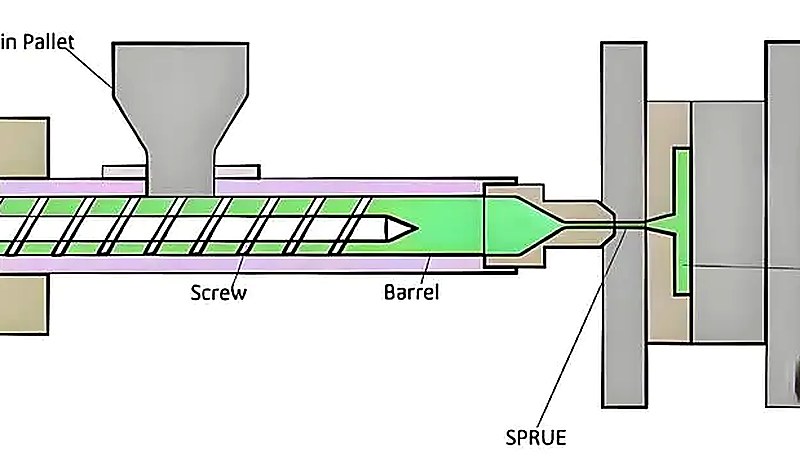
기본부터 시작하세요: 호퍼에 실제로 충분한 원료가 있나요? 펠렛이 뭉쳐서 공급을 막는 피드 스로트 브리징(Feed throat bridging)은 특히 고습기 또는 불규칙한 형태의 펠렛에서 사람들이 인정하는 것보다 더 자주 발생합니다. 원료 공급이 양호함을 확인한 후에는 배기 상태를 확인하세요. 갇힌 공기는 역압을 생성하여 들어오는 용융물의 흐름을 방해합니다. 배기구는 0.0005~0.0015인치 깊이여야 합니다; 너무 얕으면 가스가 빠져나가지 못하고, 너무 깊으면 플래시(flash)가 발생합니다.
배기 검사가 끝나면 사출 속도와 압력을 확인하세요. 재료가 캐비티 끝에 도달하기 전에 굳어버린다면, 충전 속도를 높여 충전 단계 동안 용융물이 냉각되는 시간을 줄이세요. 이는 흐름 채널이 수 밀리초 내에 고체화될 수 있는 얇은 벽 부품에서 특히 중요합니다.
금형 설계 측면에서, 마지막으로 채워지는 영역을 향해 재료를 유도하는 약간 두꺼워진 단면인 흐름 선도부는 완전 충전과 만성적인 충전 불량 사이의 차이를 만들 수 있습니다. 사출 금형 이 문제는 설계 단계에서 해결해야 합니다; 금형이 제작된 후에는 공정 조정만으로 선택지가 제한됩니다.
엔지니어들이 주의해야 할 다른 결함은 무엇인가요?
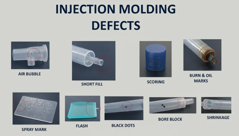
플래시(flash), 싱크 마크(sink mark), 휨(warpage), 단기(short shot)는 '네 가지 주요 불량'이지만, 생산 현장에서 마주칠 유일한 문제는 아닙니다. 엔지니어들을 당황하게 만드는 세 가지 불량이 더 있습니다:
번 마크(디젤 효과): 갇힌 공기가 배기구를 통해 빠져나가는 속도보다 빠르게 압축되면 온도가 급상승하여 플라스틱이 그을립니다. 채우기 끝 부분에 보통 검은색 또는 갈색 변색이 나타납니다. 해결책: 배기 개선, 사출 속도 감소 또는 둘 다를 적용하세요.
용접 라인: 두 개의 흐름 전선(flow front)이 만나는 곳—일반적으로 구멍이나 코어 핀 주변—에서는 용접선(weld line)이 발생합니다. 일부 재료와 형상에서는 이는 단순히 외관상의 문제입니다. 구조용 응용 분야에서는 약점이 될 수 있습니다. 더 높은 용융 온도와 더 빠른 사출 속도는 일반적으로 전선들이 더 잘 융합되도록 도와줍니다.
제팅: 부드럽게 전진하는 흐름 전면 대신, 재료가 호스처럼 게이트를 통해 분사되어 캐비티를 가로질러 뱀처럼 움직입니다. 부품 표면에 물결 모양의 벌레 같은 선이 보입니다. 근본 원인은 일반적으로 벽 두께에 비해 게이트 개구부가 너무 크고, 고속 사출이 결합된 경우입니다. 속도를 줄이거나 게이트 설계를 조정하면 해결됩니다.
시각적 예시가 포함된 완전한 불량 유형 카탈로그는 당사의 사출 성형 불량 가이드를 참조하세요. 불량의 전체적인 상황을 이해하면 패턴을 인식하는 데 도움이 됩니다—가끔 단기(short shot)처럼 보이는 것이 실제로는 가스 트랩(gas trap)일 수 있으며, 해결 방법은 완전히 다릅니다.
사출 성형 불량에 관한 자주 묻는 질문
금형 온도가 플래시 형성에 영향을 미칠 수 있나요?
예. 더 높은 금형 온도는 캐비티로 들어가는 용융물의 점도를 낮춰 재료가 파팅 라인 간극으로 스며들기 쉽게 만듭니다. 플래시(flash) 문제가 있다면, 공정 조정 중 첫 번째 단계로 금형 온도를 5–10°C 낮추어 보세요.
싱크 마크는 왜 항상 리브 근처에 나타날까요?
리브는 명목 벽과의 교차점에 국부적인 질량을 추가합니다. 그 교차점은 주변 벽보다 두껍고, 더 오래 열을 보유하며, 냉각되면서 더 많이 수축합니다. 코어가 수축하면 표면을 안쪽으로 당깁니다. 리브 두께를 벽 두께의 40–60%로 유지하면 싱크 마크를 유발하는 질량 집중을 방지할 수 있습니다.
백 압력(Back Pressure)이 단기(Short Shot)에 어떤 영향을 미치나요?
낮은 백압은 불균일한 용융 밀도(스크류 앞의 용융된 재료와 반고체 재료의 불균일한 혼합)를 초래합니다. 스크류가 전진할 때 사출 용적을 예측할 수 없어 부족한 양이 나올 수 있습니다. 백압을 50–100 psi 증가시키면 균일한 용융과 일정한 사출 용적을 보장합니다.
휨은 항상 냉각 문제인가요?
아니요. uneven cooling이 가장 일반적인 원인이지만, warpage는 excessive packing pressure로 frozen-in internal stress를 생성하거나, high-shrinkage resins(PE 등)로 poor material selection을 하여 PC보다 훨씬 더 많이 warp되거나, asymmetric part geometry에서도 발생할 수 있습니다. warpage를 진단하려면 네 가지 요소를 모두 확인해야 합니다.
Short Shot과 Gas Trap의 차이는 무엇입니까?
short shot은 cavity에 충분한 material이 도달하지 못하는 것입니다—flow가 멈춘 곳에 clean, rounded edges가 있습니다. gas trap 또는 diesel effect는 air가 compressed되고 ignited되어 plastic surface를 burn할 때 발생합니다. gas trap은 black 또는 brown burn marks를 남기고, short shot은 smooth boundaries를 가진 unfilled areas를 남깁니다.
물질 수분이 사출 성형 결함을 유발할 수 있습니까?
물론입니다. 나일론, 폴리카보네이트, PET 등 흡습성 물질은 공기 중의 수분을 흡수합니다. 처리 전에 적절하게 건조되지 않으면, 물이 내부에서 기화하여 스플레이 또는 은색 줄무늬, 공동, 구조적 약점을 생성합니다. 성형 전에 항상 dew-point meter로 수분 함량을 확인하세요.
결함 방지를 위한 적절한 기계를 어떻게 선택하나요?
프로젝트된 부품 면적에 10–20%의 안전 마진을 적용하여 기계 토너지를 맞추세요. 너무 작으면 플래시가 발생하고, 너무 크면 에너지를 낭비하고 몰드를 과도하게 clamping할 위험이 있습니다. 기계는 또한 부품 무게와 cycle time 요구 사항에 충분한 shot volume과 plasticizing capacity를 갖추어야 합니다.
사출 성형 결함 해결은 해결책 목록을 암기하는 것이 아니라 체계적인 접근 방식을 구축하는 것입니다. 우리 공장에서는 엔지니어들이 90.0톤부터 1850.0톤까지의 프레스에서 동일한 체크리스트를 사용하며, 한 번에 하나의 변수를 변경하는 것을 권장합니다. 생산을 시작하기 전에 0.5mm shutoff wear, 5.0% pressure steps 및 검증된 샘플을 확인하세요.
사출 성형 결함 해결은 해결책 목록을 암기하는 것이 아니라 체계적인 접근 방식을 구축하는 것입니다. 우리 Shanghai 공장에서는 엔지니어링 팀이 90T부터 1850T까지의 45대 기계에서 동일한 체크리스트를 사용합니다, random changes는 random defects를 생성하기 때문입니다. Process-Mold-Material triangle로 시작하여 한 번에 하나의 변수를 변경하고, 생산을 시작하기 전에 항상 샘플로 결과를 확인하세요.
결함을 방지하는 최적의 시기는 몰드가 제작되기 전, 제조 가능성 설계(DFM) 검토 단계입니다. uniform wall thickness, 적절한 rib proportions, adequate draft 및 잘 배치된 gates는 생산이 시작되기 전에 대부분의 결함을 제거합니다.
ZetarMold은 45대의 사출 성형기(90T–1850T)를 운영하며, 120명 이상의 생산 직원과 평균 10년 이상의 경력을 가진 8명의 고급 엔지니어가 있습니다. 우리의 6단계 QC 프로세스와 400개 이상의 물질 데이터베이스는 결함이 당신의 문제가 되기 전에 조기에 발견할 수 있음을 의미합니다.
완고한 결함 해결이 필요하거나 tooling 전에 DFM 검토를 원하십니까? 무료 견적을 요청하면 엔지니어링 팀이 24시간 내에 프로젝트를 검토합니다.
-
injection molding sink mark: injection molding sink mark은 사출 성형 부품 표면의 depression을 의미하며, 일반적으로 ribs 또는 thick sections 위에서 내부 material이 cooled outer skin보다 더 많이 shrinkage할 때 형성됩니다. ↩
-
injection molding warpage: injection molding warpage은 사출 성형 부품의 warpage를 의미하며, 주로 differential shrinkage—uneven cooling rates 또는 fiber orientation으로 인해 internal stress와 geometric distortion이 발생합니다. ↩
-
short shot troubleshooting: short shot troubleshooting은 사출 시 mold cavity가 완전히 채워지지 않아 material이 부족한 상태를 의미하며, 일반적으로 insufficient pressure, inadequate venting 또는 premature material freeze로 발생합니다. ↩


