 コンテンツへスキップ

- 大きな問題です。金型の中で完璧に見える部品でも、取り出されて室温まで冷える瞬間に、ねじれたり、反ったり、カップ状になったりすることがあります。根本原因はほぼ常に
- Flash usually means clamping force or tooling alignment; sink marks point to packing pressure or thick sections.
- Warpage is driven by differential shrinkage from uneven cooling or fiber orientation.
- Short shots often require venting improvements or injection speed increases.
- Prevention is cheaper than post-processing: design defects out before steel is cut.
What Is the Real Cost of Injection Molding Defects?
The real cost of injection molding defects is defined by the function, constraints, and tradeoffs explained in this section. If you are comparing vendors or planning procurement, our injection molding supplier sourcing guide covers RFQ prep, qualification, and commercial risk checks.
Injection molding defects are expensive because scrap consumes material, press time, labor, and customer trust. In our factory reviews, our engineers start with a 3-part check: process window, mold condition, and material behavior. On a 100,000-part run, even 5.0% scrap means 5,000 parts before rework starts.
Injection molding defects are expensive because scrap consumes material, press time, labor, and customer trust. In our factory reviews, we start with a 3-part check: process window, mold condition, and material behavior. On a 100,000-part run, even 5% scrap means 5,000 bad parts before rework starts.
You just pulled a batch of parts off the press and 18% of them have visible defects. That is not a cosmetic problem—it is money walking out the door. Scrap, rework, delayed shipments, and angry customers all trace back to the same root: something in your process, mold, or material was not dialed in.
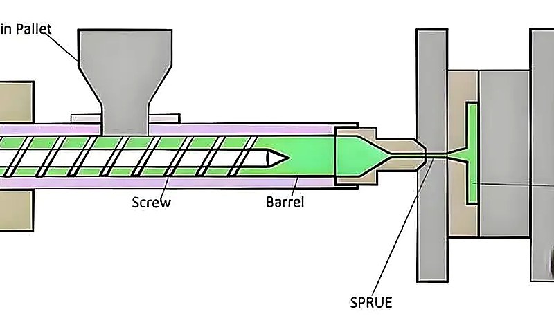
の中で 射出成形 industry, understanding injection molding defect classification is one of the most valuable skills an engineer can develop. The classic framework is the Process-Mold-Material triangle: almost every defect has one primary root cause and two contributing factors. The trick is isolating which variable is the culprit before you start turning knobs.
Semi-crystalline polymers like Polypropylene (PP) and Nylon (PA) shrink significantly more than amorphous ones like ABS or Polycarbonate (PC). That means a defect-free part in ABS can warp badly if you swap in PA66 without adjusting your process. Knowing your material’s shrinkage behavior is not optional—it is step zero of any serious troubleshooting effort.
The financial impact compounds quickly. A 5% scrap rate on a 100,000-part run means 5,000 wasted parts—plus the machine time, material, and labor that went into making them. In medical or automotive applications, a single defective part reaching the customer can trigger recalls, regulatory headaches, and reputational damage that costs far more than any tooling fix would have.
What Causes Flash and How Can You Fix It?
フラッシュ—that thin, unwanted flap of plastic escaping the mold cavity—is one of the most common and frustrating defects. It shows up at the parting line, around ejector pins, or at any seam where two mold halves meet. If you have ever seen a razor-thin lip of plastic on the edge of a part, that is flash.
The immediate cause is always the same: the cavity pressure exceeded the clamping force at some point during injection. But the underlying reason can be any of several things, and just cranking up the clamp tonnage is not always the answer—too much clamp force can crush vents and create gas trap problems downstream.
| Category | Root Cause | Engineering Fix |
|---|---|---|
| プロセス | Injection pressure too high | Reduce pressure by 5–10% and observe |
| プロセス | Clamping force insufficient | Verify tonnage ≥ 2.5–5 tons per sq inch of projected area |
| プロセス | Melt temperature excessive | Lower barrel temperature to reduce viscosity |
| 金型 | Parting line damage or debris | Clean mold surfaces; check for worn edges |
| 金型 | Tooling deflection under pressure | Add or verify support pillars behind cavities |
| 素材 | Low-viscosity resin (e.g., PA, POM) | Adjust packing profile to reduce peak cavity pressure |
Process adjustments should always be your first move. Drop injection pressure in 5% increments and watch whether the flash diminishes. If it does not, the problem is likely mechanical—parting line wear, insufficient support pillars, or thermal expansion causing mold plates to bow. Each of these requires a different fix, which is why changing only one variable at a time matters so much.
“Reducing injection speed can help eliminate flash by lowering the peak cavity pressure at the moment of filling.”真
Slower injection speeds reduce shear heating and the momentary pressure spike inside the cavity, which means less force pushing the mold halves apart.
“Increasing the clamp tonnage is always the first and safest solution to eliminate flash.”偽
While low clamp tonnage causes flash, excessive tonnage can crush vents, damage the mold parting line, and worsen gas entrapment. Always optimize injection pressure and melt temperature first.
When flash cannot be fully eliminated through process adjustments, flash removal methods become necessary. The three main approaches are: manual trimming with knives or scrapers (labor-intensive but fine for small batches), cryogenic deflashing using liquid nitrogen to embrittle the flash before tumbling (excellent for high-volume small parts), and robotic routing for large automotive or industrial components requiring tight tolerances.
What Engineering Fixes Solve Sink Marks Effectively?
Sink marks are those depressions you see on the show surface of a part, usually right above a rib, boss, or any thick section. They happen because injection molding sink mark1 dictate that the interior of a thick wall stays hot longer than the exterior skin. As the core finally cools and shrinks, it pulls the visible surface inward.
The first thing to check is your packing phase. If holding pressure is too low or ends too early (before the gate freezes), the cavity cannot compensate for volumetric shrinkage. A practical rule: packing time should be at least 1–2 seconds longer than the gate seal time. Monitor your screw cushion—if it bottoms out to zero, you are not transferring any pressure to the cavity, and sink marks are guaranteed.
Melt temperature matters too. Running hotter than necessary means more volumetric shrinkage as the material cools. Stay within the resin manufacturer’s recommended range, but bias toward the lower end if sink marks are your primary issue. A 10°C reduction in barrel temperature can make a measurable difference on thick-section parts.
But process alone will not save you if the part design is working against you. The rib thickness rule is non-negotiable: ribs should be 40–60% of the adjacent nominal wall thickness. Go thicker and you are guaranteeing a sink mark. Other design strategies include coring out thick sections to achieve uniform wall thickness and gating into the thickest area so packing pressure reaches the regions most prone to shrinkage.

At ZetarMold’s Shanghai facility, our 8 senior engineers use a 6-step quality control process to catch sink marks before they reach customers. With 45 injection molding machines (90T–1850T) and 400+ materials in our database, we have seen just about every material-defect combination and know the packing profiles that work.
What Strategies Work for Preventing Part Warpage?
反り is the big one. A part that looks perfect in the mold can twist, bow, or cup the moment it comes out and cools to room temperature. The root cause is almost always 機械のトンネージを、部品の投影面積に10〜20%の安全マージンを加えて一致させてください。小さすぎるとフラッシュが発生し、大きすぎるとエネルギーを浪費し、金型を過クランプするリスクがあります。また、機械は部品重量とサイクルタイム要件に対応する十分な射出容量と可塑化能力を備えている必要があります。2: one area of the part shrinks more or faster than another, building up internal stress that eventually causes deformation.
The three main drivers of warpage are uneven cooling, fiber orientation, and ejection stress. Let us break each one down with practical fixes you can apply on your next project.
| ファクター | What Happens | How to Fix It |
|---|---|---|
| Cooling Non-Uniformity | One mold half runs hotter; the part cools unevenly | Separate cooling circuits for core and cavity; target ΔT < 5°C |
| Fiber Orientation | Glass fibers align with flow; shrinkage becomes anisotropic | Adjust gate location; consider fiber-neutral fill strategies |
| Ejection Stress | Part ejected too hot deforms under pin pressure | Increase cooling time; verify ejector pin force is balanced |
| Wall Thickness Variation | Thick sections shrink more than thin ones | Core out thick areas; target uniform wall thickness within ±10% |
Material selection also plays a huge role. High-shrinkage semi-crystalline materials like PE, PP, and PA are far more warp-prone than amorphous materials like PC or ABS. If warpage is a critical concern, consider switching to a low-shrinkage grade or a filled compound—but note that glass-filled nylon introduces its own anisotropy challenges.
“Differential shrinkage is the primary cause of warpage in injection molded parts.”真
When different regions of a part shrink at different rates due to uneven cooling, wall thickness variations, or anisotropic material behavior, internal stresses build up and cause deformation.
“Cooling channels should be placed as far from the mold cavity as possible to prevent thermal shock.”偽
Cooling channels should be conformal or placed close to the cavity surface to ensure rapid and uniform heat removal. Distance reduces cooling efficiency and worsens warpage.
For complex geometries—think automotive brackets or medical device housings—conventional straight-drilled cooling channels often cannot follow the part contour closely enough. That is where conformal cooling comes in. Using 3D-printed metal mold inserts with channels that follow the cavity surface, you can achieve dramatically more uniform cooling and cut warpage significantly.
How Should Engineers Approach Short Shots Troubleshooting?
A short shot is exactly what it sounds like: the mold did not fill completely. You end up with a part that is missing material—sometimes just a thin section at the end of flow, sometimes a major portion of the geometry. It is one of the most visible defects and often one of the easiest to diagnose if you follow a systematic short shot troubleshooting3 approach.
Start with the basics: is there actually enough material in the hopper? Feed throat bridging—where pellets pack together and block the feed—happens more often than people admit, especially with high-moisture or irregularly shaped pellets. Once you confirm material feed is good, check your venting. Trapped air creates backpressure that fights the incoming melt. Vents should be 0.0005–0.0015 inches deep; too shallow and gas cannot escape, too deep and you get flash.
If venting checks out, look at your injection speed and pressure. If the material is freezing before it reaches the end of the cavity, increasing fill speed gives the melt less time to cool during the fill stage. This is especially critical for thin-wall parts where the flow channel can solidify in milliseconds.
On the mold design side, flow leaders—slightly thickened sections that guide material toward last-to-fill areas—can make the difference between a complete fill and chronic short shots. The 射出成形金型 design phase is where you address this; once the tool is built, your options are limited to process tweaks.
What Other Defects Should Engineers Watch For?
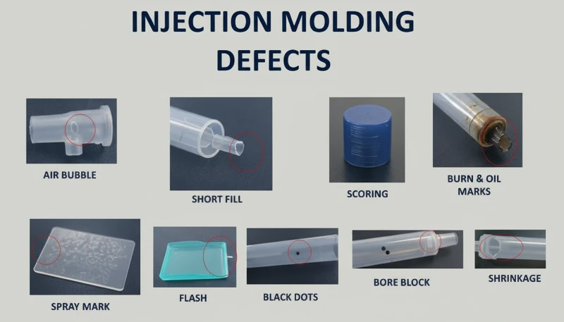
Flash, sink marks, warpage, and short shots are the “big four,” but they are not the only problems you will encounter on a production floor. Here are three more that catch engineers off guard:
Burn marks (diesel effect): When trapped air gets compressed faster than it can escape through vents, the temperature spikes and scorches the plastic. You will see black or brown discoloration, usually at the end of fill. The fix: improve venting, reduce injection speed, or both.
溶接ライン: Where two flow fronts meet—typically around a hole or core pin—you get a weld line. In some materials and geometries, this is just cosmetic. In structural applications, it can be a weak point. Higher melt temperature and faster injection speed usually help fuse the fronts better.
Jetting: Instead of a smooth advancing flow front, the material shoots through the gate like a hose and snakes across the cavity. You see wavy, worm-like lines on the part surface. The root cause is usually too large a gate opening relative to the wall thickness, combined with high injection speed. Reducing speed or adjusting the gate design solves it.
For a complete catalog of defect types with visual examples, see our injection molding defects guide. Understanding the full landscape of defects helps you recognize patterns—sometimes what looks like a short shot is actually a gas trap, and the fix is completely different.
Frequently Asked Questions About Injection Molding Defects
Can Mold Temperature Affect Flash Formation?
Yes. Higher mold temperatures lower the viscosity of the melt as it enters the cavity, making it easier for material to seep into the parting line gap. If you are battling flash, try reducing mold temperature by 5–10°C as one of your first process adjustments.
Why Do Sink Marks Always Appear Near Ribs?
Ribs add localized mass at the intersection with the nominal wall. That intersection is thicker than the surrounding wall, retains heat longer, and shrinks more as it cools. As the core contracts, it pulls the surface inward. Keeping ribs at 40–60% of wall thickness prevents the mass concentration that causes sinks.
How Does Back Pressure Influence Short Shots?
Low back pressure produces inconsistent melt density—an uneven mix of melted and semi-solid material in front of the screw. When the screw pushes forward, the shot volume is unpredictable, and you can come up short. Increasing back pressure 50–100 psi ensures a homogeneous melt and consistent shot size.
Is Warpage Always a Cooling Problem?
No. While uneven cooling is the most common cause, warpage can also come from excessive packing pressure creating frozen-in internal stress, poor material selection with high-shrinkage resins like PE that warp far more than PC, or asymmetric part geometry. Diagnosing warpage requires checking all four factors.
What Is the Difference Between a Short Shot and a Gas Trap?
A short shot is simply not enough material reaching the cavity—clean, rounded edges where the flow stopped. A gas trap or diesel effect occurs when air is compressed and ignites, burning the plastic surface. Gas traps leave black or brown burn marks, while short shots leave unfilled areas with smooth boundaries.
Can Material Moisture Cause Injection Molding Defects?
Absolutely. Hygroscopic materials like Nylon, Polycarbonate, and PET absorb moisture from the air. If not properly dried before processing, the water vaporizes inside the barrel and creates splay or silver streaks, voids, or structural weakness. Always verify moisture content with a dew-point meter before molding.
How Do You Choose the Right Machine for Defect Prevention?
Match the machine tonnage to the projected area of your part with a safety margin of 10–20%. Too small and you get flash; too large and you waste energy and risk over-clamping the mold. The machine should also have sufficient shot volume and plasticizing capacity for your part weight and cycle time requirements.
射出成形の欠陥、フラッシュ、シンクマーク、反り、ショートショット、プロセスドリフト、金型摩耗、および金型設計の問題をトラブルシューティングします。
Troubleshooting injection molding defects is not about memorizing a list of fixes; it is about building a systematic approach. In our Shanghai factory, our engineering team uses the same checklist across 45 machines from 90T to 1850T, because random changes create random defects. Start with the Process-Mold-Material triangle, change one variable at a time, and always verify your results with samples before releasing production.
The best time to prevent defects is during design for manufacturability (DFM) review, before the mold is built. Uniform wall thickness, proper rib proportions, adequate draft, and well-placed gates eliminate the majority of defects before production even starts.
ZetarMold operates 45 injection molding machines (90T–1850T) with 120+ production staff and 8 senior engineers averaging 10+ years of experience. Our 6-step QC process and 400+ material database mean we catch defects early—before they become your problem.
Need help resolving a stubborn defect or want a DFM review before tooling? Request a Free Quote and our engineering team will review your project within 24 hours.
-
injection molding sink mark: injection molding sink mark refers to sink marks are depressions on the surface of an injection molded part, typically forming above ribs or thick sections where the interior material shrinks more than the cooled outer skin. ↩
-
injection molding warpage: injection molding warpage refers to warpage in injection molded parts is primarily caused by differential shrinkage—uneven cooling rates or fiber orientation leading to internal stress and geometric distortion. ↩
-
short shot troubleshooting: short shot troubleshooting refers to a short shot occurs when the mold cavity is not completely filled during injection, resulting in missing material typically caused by insufficient pressure, inadequate venting, or premature material freeze. ↩


