 콘텐츠로 건너뛰기

Injection molds are precision tools that define the 품질1, cost, and speed of every 플라스틱2 part you produce. Yet many buyers and engineers overlook a critical step between mold completion and full production: a rigorous acceptance inspection. Mold acceptance criteria are the agreed-upon standards that determine whether a newly manufactured or reconditioned 사출 금형3 is fit for production. Without clear criteria, you risk expensive rework, production delays, and parts that fail quality checks downstream. This guide walks you through the acceptance standards across every phase — from design review to final trial — so you know exactly what to check, what to measure, and what to document before signing off.
- Mold acceptance criteria cover design, manufacturing, and testing phases — each with specific checkpoints.
- Dimensional accuracy, surface finish, and material certification are the three pillars of mold acceptance.
- A structured trial run with documented sample parts is mandatory before approving any mold.
- Industry standards such as SPI classifications and ISO 20457 provide objective acceptance benchmarks.
- Using a standardized checklist reduces rework risk and shortens time-to-production.
What Are Injection Mold Acceptance Criteria?
Injection mold acceptance criteria are measurable standards that determine whether a completed mold is fit for production.
더 넓은 관점을 위해 우리의 injection molding complete guide 프로세스 기본 원리, 재료 행동 및 생산 결정을 포함합니다.
In practice, acceptance criteria translate into a checklist that covers everything from cavity dimensions (typically within ±0.01 mm for precision molds) to surface finish grades (SPI A-1 through D-3), cooling channel flow rates, and ejection system reliability. The goal is simple: confirm that the mold will produce parts that meet your specifications consistently and efficiently over its expected lifespan.
In our Shanghai factory, we run 47 injection molding machines from 90T to 1850T, and every new mold goes through a three-stage acceptance protocol before release for production. This includes a dimensional audit, a 200-shot trial run, and a final surface inspection under 10x magnification.
What Are the Design Phase Acceptance Standards?
Design acceptance standards verify that the mold design meets requirements and passes flow analysis before steel is cut.
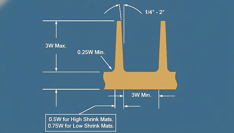
Before machining begins, the mold design must pass several acceptance gates. First, the design must match the product specifications exactly — every dimension, draft angle, and surface finish requirement must be reflected in the CAD model. Second, the mold structure itself must be sound: parting line selection, gate location, cooling channel layout, and ejection method all need to be validated. A poorly chosen gate location alone can cause weld lines, air traps, or uneven filling that no amount of post-machining polish can fix.
At this stage, mold flow analysis software such as Moldflow or Moldex3D is essential. These tools simulate the filling, packing, and cooling phases, predicting potential defects before the mold exists. The analysis should confirm that fill time is balanced across all cavities, maximum injection pressure stays within machine limits, and weld lines fall in non-critical areas. Any design that fails these simulations should be revised, not approved.
A proper design acceptance checklist should include: product dimension compliance (GD&T review), mold structure feasibility (parting line, slide, lifter evaluation), standard component selection (DME, HASCO, or LKM), cooling circuit design (thermal balance verification), and mold flow analysis sign-off. Each item should have a clear pass/fail criterion. In our experience, skipping the mold flow sign-off is the single most common cause of mold rejection at the trial stage.
What Manufacturing Quality Checks Are Required?
Manufacturing quality checks are inspections covering material certification, machining dimensions, surface treatment, and assembly accuracy.
Material selection is the foundation. Mold steels such as P20, H13, S136, and 718H each serve different production volumes and surface finish requirements. Every steel lot must come with a mill certificate confirming composition and hardness. Without this documentation, you have no traceability — and no basis for accepting the mold. Hardness testing (typically Rockwell C scale) should be performed on the actual mold components, not just assumed from the certificate.
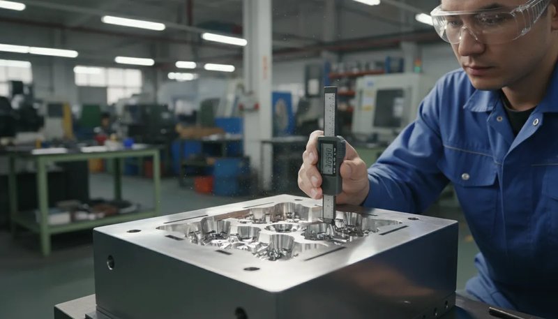
Machining accuracy directly determines part quality. Core and cavity dimensions should be measured against the CAD model using coordinate measuring machines (CMM), with critical dimensions held to ±0.005 mm or tighter for precision molds. Surface roughness should match the SPI classification specified in the design — SPI A-1 requires mirror finish, while SPI D-3 allows light blast texture. Each surface zone must be measured and recorded.
Assembly accuracy ties everything together. The mold halves must align within the specified tolerance (typically ≤ 0.02 mm for precision molds), guide pins and bushings must operate smoothly, and all moving components — slides, lifters, angle pins — must function without binding. A mold that machines perfectly but assembles poorly will produce parts with flash, mismatch, or ejection marks.
Key manufacturing acceptance checks: Steel hardness — Rockwell C tester, ±2 HRC, must match mill certificate. Cavity dimensions — CMM scan, ±0.005–0.01 mm, must match CAD model. Surface roughness — Profilometer, SPI class range A-1 to D-3. Mold alignment — Bluing check, ≤ 0.02 mm, no flash. Ejector travel — Full stroke, smooth, no binding or marks.
What Happens During Mold Testing and Trial?
Mold testing and trial are production-equivalent test runs verifying part quality, cycle time, and thermal performance before acceptance.
The trial run is where theory meets reality. Before the trial, verify that the molding machine is appropriate for the mold — the clamping force must exceed the projected area pressure, and the shot volume must fall within 20 to 80 percent of the barrel capacity. During setup, install thermocouples in the mold to monitor cavity surface temperature at each zone. This data becomes part of your acceptance documentation.
A proper acceptance trial runs a minimum of 50 to 200 shots. The first 10 to 20 shots establish process parameters; these are not evaluated for part quality. From shot 20 onward, collect consecutive samples for dimensional inspection, visual grading, and weight consistency. Weight variation across 50 consecutive shots should be within ±0.2 percent — any more suggests unstable filling or inconsistent packing.

Beyond part quality, the trial verifies mold function under realistic conditions. The mold must open and close smoothly for at least 200 consecutive cycles without manual intervention. The cooling system must achieve steady-state temperatures within the specified range (typically ±3 °C across all zones). And the ejection system must remove parts cleanly every cycle, without marks, deformation, or stuck parts.
Complete documentation is a non-negotiable acceptance requirement. At minimum, the mold maker should deliver: the approved mold design drawings, steel certificates, dimensional inspection reports, mold trial reports with process parameters, sample parts from the trial, and a maintenance guide. Without this documentation package, the mold cannot be considered accepted — regardless of how well it performed during the trial.
What Dimensional and Structural Inspections Are Mandatory?
Dimensional and structural inspections are mandatory checks including cavity measurements, parting line alignment, and cooling flow testing.
Dimensional accuracy inspection is the most quantifiable acceptance test. Using a CMM, every critical cavity dimension should be measured and compared against the CAD nominal, with results falling within the specified tolerance band. For multi-cavity molds, each cavity must be measured independently — cavity-to-cavity variation should not exceed 50 percent of the part tolerance. Shrinkage compensation must also be verified: the mold dimensions should account for material-specific shrinkage rates, which range from 0.2 percent for amorphous materials like PC to 2.5 percent for semi-crystalline materials like POM.
Structural review focuses on the mold mechanical integrity. The parting line must seal completely under clamping force — verified with a bluing check or prussian blue test. Vent channels must be present at all flow ends, typically 0.01 to 0.03 mm deep, to allow trapped air and gases to escape. Support pillars must prevent plate deflection under injection pressure, which can cause flash on large-area parts. Any structural deficiency here will only worsen over production life.
Our in-house mold manufacturing facility produces over 100 mold sets per month, and every mold undergoes a dimensional audit using CMM before trial. We have learned that catching a 0.02 mm cavity deviation at the measurement stage saves ten times the cost of finding it during trial.
Cooling efficiency directly impacts cycle time and part quality. Flow rate through each cooling circuit should be measured — turbulent flow (Reynolds number above 4000) is required for effective heat transfer. Temperature differential between inlet and outlet should not exceed 2 to 3 °C. Higher differentials indicate restricted flow or insufficient circuit design. Mold clamping stability is verified by checking for flash formation at the parting line during normal production pressure. Any flash indicates insufficient clamping force, mold face damage, or plate deflection.
How Do Material and Surface Standards Affect Acceptance?
Material and surface standards are acceptance criteria that determine whether mold steel and finish will withstand production demands.
Material acceptance starts with verifying the steel grade against the design specification. Common mold steels include P20 (pre-hardened, good for 100K+ shots), H13 (through-hardened, excellent for high-volume and hot-runner molds), S136 (stainless, corrosion-resistant, ideal for transparent parts and medical applications), and 718H (pre-hardened, cost-effective for medium-volume production). Each grade must be verified by its mill certificate and confirmed by on-site hardness testing.
Surface quality evaluation has two dimensions: the mold surface itself and the part surface it produces. The mold surface must meet the specified SPI classification, verified with a profilometer. For polished surfaces (SPI A-1 and A-2), any visible tool marks, orange peel, or polishing lines are grounds for rejection. For textured surfaces (SPI C and D), the texture must be uniform and match the approved sample. The part surface, in turn, must reproduce the mold finish faithfully — any gloss variation, flow marks, or weld lines visible on the part surface indicate mold surface issues.
The finished product sample trial is the ultimate test. Sample parts from the acceptance trial must be measured against the part drawing, inspected for visual defects, and tested for functional requirements (fit, assembly, drop test, or other application-specific tests). Only when the parts consistently meet all requirements across multiple consecutive shots can the mold be accepted. Material-specific behavior also becomes apparent — glass-filled nylon requires harder mold surfaces to prevent abrasive wear that would degrade surface finish within the first 10,000 cycles.
What Factors Influence Mold Acceptance Standards?
The key factors influencing acceptance are product complexity, production volume, manufacturer capability, and applicable industry standards.
Product complexity is the biggest driver. A simple two-plate mold for a polypropylene clip has far fewer acceptance checkpoints than a multi-slide, hot-runner mold for an automotive interior panel with Class A surface requirements. Complex molds demand more measurement points, tighter tolerances, and longer trial runs to validate. Production volume also shapes the acceptance bar: a prototype mold for 500 parts may accept compromises in surface finish and cooling efficiency that a production mold for 5 million shots cannot.
The technical level of the mold manufacturer matters because it determines what can be measured and verified. A shop with CMM capability, surface roughness measurement, and thermal imaging can provide objective acceptance data. A shop without these tools can only offer subjective visual assessment — which is insufficient for precision molds. Industry standards provide the common language: the SPI mold classification system (Class 101 through 105) defines expected mold life and precision levels, while ISO 20457 specifies technical specifications for 사출 금형.
Cost control is the final balancing factor. Acceptance criteria should be proportional to the mold intended use. Over-specifying a prototype mold wastes time and money; under-specifying a production mold risks quality failures. The key is to align acceptance criteria with the mold classification: SPI Class 101 (over 1,000,000 shots) demands the tightest tolerances and most comprehensive documentation, while SPI Class 105 (under 500 shots) accepts wider tolerances and minimal documentation.
SPI mold classes define expectations: 클래스 101 — over 1M shots, ±0.005 mm, SPI A-1, full PPAP. 클래스 102 — 500K to 1M shots, ±0.01 mm, SPI A-2 to B-1, detailed report. 클래스 103 — 100K to 500K shots, ±0.02 mm, SPI B-1 to C-1, standard report. 클래스 104 — under 100K shots, ±0.05 mm, SPI C-3, basic report. 클래스 105 — under 500 shots, ±0.1 mm, as-machined, minimal documentation.
“A mold that passes dimensional inspection but produces defective parts during trial should still be rejected.”True
Correct. The trial run is the definitive acceptance test. If parts fail quality checks despite perfect cavity dimensions, the mold has functional issues — often related to gate design, cooling, or venting — that must be resolved before acceptance.
“SPI Class 105 molds require the same documentation as Class 101 molds.”False
Incorrect. SPI Class 101 molds (over 1,000,000 shots) require full PPAP documentation with dimensional reports, trial records, and maintenance guides. Class 105 molds (under 500 shots) require minimal documentation because they are built for prototyping, not production.
Understanding the distinction between visual assessment and instrument-based measurement is critical for acceptance. Many mold buyers assume that a good visual appearance means the mold passes surface standards, but surface finish tolerances are measured in micrometers and cannot be reliably judged by eye alone. Similarly, dimensional compliance must be verified with CMM data, not caliper spot checks, because individual point measurements miss systematic deviations across the entire cavity surface.
“Mold flow analysis should be completed and approved before any steel is cut.”True
Correct. Mold flow analysis predicts filling patterns, weld line locations, and pressure requirements before manufacturing. Approving a design without flow analysis is the most common cause of mold rejection at trial stage.
“Surface finish acceptance only needs to be checked visually.”False
Incorrect. Surface finish must be measured with a profilometer against the specified SPI classification. Visual inspection alone cannot distinguish between SPI A-1 and SPI A-2, and the difference affects both part appearance and mold cost.
결론
Injection mold acceptance criteria are your insurance against production failures and costly rework. By applying structured standards across design, manufacturing, and testing, you ensure every mold has been verified against objective criteria.
With 20+ years of injection molding and tooling experience, and ISO 9001 / ISO 13485 / ISO 14001 / ISO 45001 certified systems, ZetarMold applies a standardized three-stage acceptance protocol to every mold we build. Rigorous acceptance criteria upfront reduce production issues significantly.
Need a Custom Injection Mold with Full Acceptance Documentation?
Get competitive pricing, DFM feedback, mold flow analysis, and a complete acceptance report from ZetarMold engineering team. We work with 400+ materials and produce 100+ mold sets per month in our Shanghai facility.
Available services: Mold Design and Flow Analysis — CAD with Moldflow simulation. Full Acceptance Trial — 200-shot trial with inspection. Documentation Package — Steel certs, CMM reports, trial data. Get a Quote - Request a free quote with 24-hour response.
자주 묻는 질문
자주 묻는 질문
What is the minimum trial shot count for mold acceptance?
Most industry standards recommend a minimum of 50 to 200 shots for mold acceptance trials. The first 10 to 20 shots are always considered process setup and are excluded from quality evaluation entirely. From shot 20 onward, consecutive parts must meet all dimensional, visual, and weight consistency requirements throughout the entire sample set. For SPI Class 101 molds with tight tolerances, 200 shots provide enough statistical confidence to verify both process stability and part consistency over the expected production run.
What SPI mold classification should I specify for my project?
Choose SPI Class 101 for high-volume production exceeding 1 million shots, such as packaging or consumer electronics. Class 102 suits mid-to-high volume from 500K to 1M shots. Class 103 works for moderate production volumes from 100K to 500K shots. Class 104 is appropriate for low-volume or bridge tooling applications. Class 105 should only be used for prototyping under 500 shots. Selecting the right class upfront properly balances mold cost against the precision and lifespan you need for your specific application and production requirements.
How do you measure mold cavity dimensions during acceptance?
Cavity dimensions are measured using a coordinate measuring machine (CMM) that maps the mold surface against the CAD nominal model. Critical dimensions are held to tolerances of plus or minus 0.005 to 0.01 mm for precision molds. For multi-cavity molds, each cavity must be measured independently, and cavity-to-cavity variation must not exceed 50 percent of the part tolerance. Shrinkage compensation is verified by comparing mold dimensions against the expected part dimensions after accounting for material-specific shrinkage rates and process conditions.
Can a mold be accepted if it has minor flash during trial?
No mold should be accepted with flash at the parting line during normal production parameters. Flash indicates one or more underlying issues: insufficient clamping force, mold face damage, plate deflection, or inadequate venting somewhere in the mold tool. While adjusting process parameters may temporarily reduce flash, the root cause must be corrected before final acceptance is granted. Accepting a mold with known flash risk will lead to progressive quality problems and significantly increased maintenance costs over the entire production life of the mold.
What documentation must accompany an accepted injection mold?
A complete mold acceptance package includes: approved mold design drawings in 2D and 3D CAD formats, steel mill certificates with composition and hardness data, CMM dimensional inspection reports with all critical dimensions mapped, surface roughness measurements against SPI classifications, mold trial report with process parameters including temperature pressure and cycle time, sample parts from the acceptance trial run, and a maintenance guide with recommended spare parts list. Automotive or medical applications may require additional PPAP or validation documentation to meet regulatory compliance.
금형 강재 선택이 인수 기준에 어떻게 영향을 미치나요?
금형 강재 등급은 경도 요구 사항, 표면 마감 능력 및 예상 금형 수명을 직접 결정하며, 이 모두는 핵심 인수 기준입니다. 28~36 HRC의 P20 예비 경화 강재는 일반적인 허용 오차를 가진 중간 생량 용도에 적합합니다. 48~52 HRC의 H13 완전 경화 강재는 핫 러너를 사용하는 대량 생산 금형에 필요합니다. 48~54 HRC의 S136 스테인리스 강재는 부식 저항성이 필요한 광학 및 의료 부품에 지정됩니다. 인수 경도 측정은 설계 사양과 정확히 일치해야 장기 금형 성능을 보장합니다.
금형 인수 과정에서 냉각 시스템 검증의 역할은 무엇입니까?
냉각 시스템 검증은 금형이 생산 중 모든 구역에서 캐비티 표면 온도를 ±3°C 범위 내에서 일정하게 유지할 수 있는지를 확인합니다. 이는 각 냉각 회로의 유량을 측정하여 레이놀즈 수가 4000 이상인 난류 흐름을 확인하고, 입구와 출구의 온도 차이가 2~3°C를 초과하지 않는지를 모니터링하여 테스트합니다. 불량한 냉각 설계는 불균일한 수축, 더 긴 사이클 시간, 부품 뒤틀림을 야기하며, 이 모두는 수정해야 하는 인수 실패 사항으로 간주됩니다.
일반적인 금형 인수 과정은 얼마나 걸립니까?
일반적인 금형 인수 과정은 금형 복잡성에 따라 3~7일의 작업일이 소요됩니다. 간단한 2판 금형은 설계 검토, 치수 검사 및 100회 사출 시험을 포함하여 2~3일 내 인수를 완료할 수 있습니다. 복잡한 다중 캐비티 또는 핫 러너 금형은 모든 캐비티의 정밀 CMM 측정, 200회 이상의 확장 시험 운전 및 모든 이동 구성 요소의 기능 테스트를 포함하여 5~7일이 필요합니다. 생산 지연을 방지하기 위해 프로젝트 일정에 인수 타임라인을 초기에 포함하십시오.


