 コンテンツへスキップ

アン 射出成形金型 is the single most expensive and critical tool in plastic manufacturing. Get it right, and you can produce millions of identical parts with tolerances measured in thousandths of an inch. Get it wrong, and every single part that comes off the machine is scrap. After 20+ years of building 射出成形 tooling in our Shanghai factory, we have seen just about every mold-making mistake there is — and this guide distills those lessons into practical, engineer-to-engineer advice you can actually use.
- An injection mold is a precision tool that shapes molten plastic into repeatable, production-quality parts
- Mold design involves 7 core subsystems: gating, cooling, ejection, venting, positioning, cavity, and frame
- Steel selection (P20, H13, S136) directly determines mold lifespan and part surface finish
- A typical production mold takes 4–8 weeks to build and costs $10,000–$100,000+ depending on complexity
- Working with an in-house mold shop reduces lead time by 30–50% compared to outsourcing
What Is an Injection Mold and Why Does It Matter?
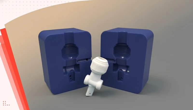
An injection mold and why does it matter is defined by the function, constraints, and tradeoffs explained in this section. An injection mold is a custom-machined steel or aluminum tool that defines the shape, surface finish, and dimensional accuracy of every plastic part produced through the injection molding process. In simple terms: the mold is a hollow metal block with a cavity cut into it. Molten plastic gets injected under high pressure into that cavity, cools, solidifies, and the mold opens to release the finished part.
Why does it matter so much? Because the mold is where quality starts. If the cavity dimensions are off by even 0.05 mm, every single part will carry that error across the entire production run — which could be 100,000 parts or more. The mold also controls surface finish (glossy, matte, textured), the location of parting lines, gate marks, and weld lines. In our factory, we regularly see parts that “almost work” because the mold was designed without enough draft angle, or the gate was placed in a high-stress area. These are expensive lessons that proper mold design prevents upfront.
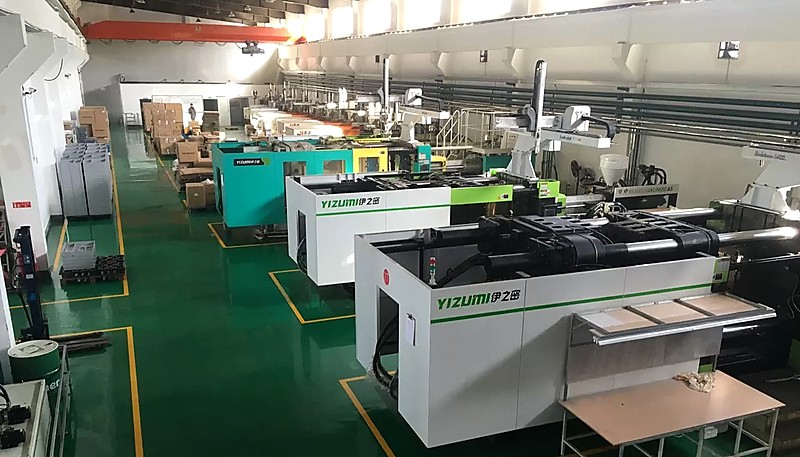
With over 20 years of experience and an in-house mold manufacturing facility, our team has built thousands of production molds — from simple single-cavity tools to complex multi-cavity molds with lifters, slides, and hot runner systems.
What Are the Key Components of an Injection Mold?
A production-grade injection mold is far more than two halves of a metal block. It is a precision assembly of 7 distinct subsystems, each with a specific job. Understanding these components is essential whether you are reviewing a mold quote or troubleshooting a production issue.
Gating System (Runner and Gate)
The gating system is the channel network that delivers molten plastic from the machine nozzle into the mold cavity. It consists of the sprue (the main vertical channel), the runners (horizontal distribution channels), and the gate (the final, narrow opening into the cavity). Gate design is one of the most critical decisions in mold engineering: the gate type (edge, submarine, pin-point, fan, diaphragm) and location directly affect part appearance, dimensional accuracy, and fill pattern. A poorly placed gate can cause jetting, air traps, or excessive weld lines — defects that no amount of processing parameter adjustment can fully fix.
冷却システム
The cooling system controls mold temperature through a network of water channels drilled into the mold plates. Efficient cooling is the single biggest factor in cycle time — which directly determines your per-part cost. A mold with well-designed conformal cooling channels (following the contour of the cavity) can reduce cycle time by 20–40% compared to traditional straight-drilled channels. In practice, cooling must be balanced: uneven cooling causes differential shrinkage, warpage, and sink marks. Our engineering team uses MOLDFLOW simulation1 to optimize cooling layout before any steel is cut.
排出システム
Once the part has cooled enough to retain its shape, the mold opens and the ejection system pushes the part off the core side. The most common ejection methods are ejector pins (round pins that push on non-critical surfaces), stripper plates (for cylindrical or box-shaped parts), and air blast ejection (for thin-walled parts). The ejection system must be designed so that the part does not warp, stick, or get damaged during removal. Ejector pin placement is an art — put them on non-visible surfaces, and make sure the ejection force is balanced to prevent part deformation.
排気システム
As molten plastic fills the cavity at injection speeds that can exceed 100 mm/s, the air that was inside the cavity has to go somewhere. The venting system provides narrow channels (typically 0.01–0.03 mm deep) that let air escape but are too small for plastic to flash through. Insufficient venting causes burn marks (diesel effect — the trapped air literally ignites), short shots (air traps prevent complete fill), and high internal pressure that can damage the mold. In our experience, venting problems account for roughly 15–20% of all mold-related quality issues we encounter during T1 sampling.
Positioning and Alignment System
The mold has three levels of positioning precision. Guide pillars provide coarse alignment during mold closing. Tapered interlocks (also called side locks) provide intermediate alignment of the mold bases. Finally, the core and cavity inserts themselves are machined to extremely tight tolerances for final, precise alignment. Each level refines the positioning — if your guide pillars are worn or the interlocks are damaged, you will see flash, dimensional shifts, and accelerated tool wear.
How Are Injection Molds Classified?
This section is about injection molds classified and its impact on cost, quality, timing, or sourcing risk. Injection molds are categorized by several dimensions, and understanding these classifications helps you specify the right tool for your production needs.
By runner system: Hot runner molds use heated channels to keep plastic molten in the runner, eliminating runner waste and reducing cycle time — ideal for high-volume production. Cold runner molds are simpler and cheaper to build, making them suitable for lower volumes or materials that degrade in hot runners.
By cavity count: Single-cavity molds produce one part per cycle. Multi-cavity molds produce multiple identical parts per cycle (e.g., a 4-cavity mold makes 4 parts per shot). Family molds produce different parts from the same mold in one cycle — useful for assemblies, but harder to balance.
By production intent: Prototype molds (sometimes called soft tools) are built from aluminum or soft steel for short runs of 100–1,000 parts — fast and inexpensive, but limited lifespan. Production molds (hard tools) are built from hardened steel for runs of 100,000 to millions of parts.
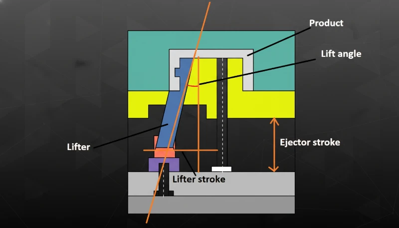
By mold structure: Two-plate molds are the simplest and most common — the mold splits into two halves at the parting line. Three-plate molds add a stripper plate that automatically separates the runner from the parts. Side-action molds incorporate slides or lifters for parts with undercuts or external threads.
What Does the Injection Mold Design Process Involve?
Mold design is where manufacturing success or failure is decided. A well-designed mold runs reliably for hundreds of thousands of cycles. A poorly designed mold will haunt you with quality issues, downtime, and expensive modifications throughout its life. The design process follows a structured sequence that experienced mold makers never skip.
Step 1: Part Analysis and DFM Review
Before any mold design work begins, the engineering team performs a thorough 製造可能設計(DFM)2 review of the part. This analysis examines wall thickness uniformity (ideal: 2–4 mm for most engineering plastics), draft angles (minimum 0.5° per side, 1–2° recommended), rib proportions (rib thickness should not exceed 60% of the nominal wall to avoid sink marks), and undercuts that will require side actions. In our experience, about 30% of the part designs we receive need at least minor modifications before they can be tooled efficiently. Catching these issues during DFM saves weeks of rework later.
Step 2: Mold Flow Simulation
Using MOLDFLOW or similar simulation software, the design team predicts how molten plastic will fill the cavity, where weld lines will form, how the part will shrink and warp, and whether the cooling layout will provide even temperature distribution. Simulation is not optional for production molds — it is the difference between a mold that works right on the first trial and one that needs three rounds of steel modifications. Our 8 senior engineers run simulations on every mold we build, using the results to optimize gate placement, cooling channel layout, and processing parameters before the first chip of steel is cut.
Step 3: Steel Selection and Mold Layout
Steel selection depends on the expected production volume, plastic material, and surface finish requirements. P20 is the workhorse mold steel — good for 100,000–500,000 cycles with most engineering plastics. H13 is a hot-work steel that handles high-temperature resins (PC, PEEK) and abrasive glass-filled materials. S136 is a stainless tool steel used when corrosion resistance is needed or when the part requires a mirror-polished SPI A-1 surface finish. The mold layout determines cavity placement, runner routing, cooling channel positions, and the overall mold base size — all of which must fit within the platen dimensions of the target injection molding machine.
Our 8 senior engineers use UG, SOLIDWORKS, and MOLDFLOW to design molds optimized for our 47 injection molding machines, ensuring every mold is purpose-built for the exact production environment where it will run.
Step 4: Detailed Design and 2D Drawing Release
The final design phase produces a complete set of 2D drawings for every mold component — cavity inserts, core inserts, slides, lifters, ejector pins, cooling plugs, and the mold base itself. Each component is toleranced for its function: cavity dimensions are held to ±0.01 mm or tighter for precision parts, while structural components have broader tolerances. The complete design package is reviewed and approved before machining begins.
“Mold flow simulation can predict weld line location and part warpage before any steel is cut.”真
Modern simulation tools like MOLDFLOW use finite element analysis to model polymer flow, cooling, and shrinkage with high accuracy. Predicting weld lines, air traps, and warpage patterns during the design phase is standard practice at professional mold shops — and prevents costly steel modifications after T1 sampling.
“Aluminum molds can produce the same part quality as hardened steel molds for high-volume production.”偽
Aluminum molds are excellent for prototyping and low-volume runs (under 10,000 parts), but they lack the wear resistance and thermal stability of hardened steel. For production runs exceeding 50,000 parts, steel molds (P20, H13, S136) maintain dimensional accuracy and surface finish far better over time.
How Is an Injection Mold Manufactured Step by Step?
Once the design is finalized and approved, the mold enters the manufacturing phase. This is where precision machining transforms raw steel blocks into the complex tool that will produce your parts. The typical timeline for a production mold is 4–8 weeks, depending on complexity.
Phase 1: Material Procurement and Roughing
The mold base and cavity/core blocks are ordered from steel suppliers. Standard mold bases (LKM, DME, HASCO) are available off-the-shelf, while cavity inserts are custom-machined from solid tool steel blocks. Roughing removes the bulk of the material using large-diameter end mills at high material removal rates. After roughing, the steel is stress-relieved (heat treated) to remove internal stresses that could cause dimensional drift later. This step is frequently skipped by low-cost mold shops — and it always shows up as dimensional instability after a few thousand cycles.
Phase 2: Precision CNC Machining and EDM
After roughing and heat treatment, the cavity and core inserts are finish-machined using high-speed CNC milling centers capable of holding ±0.005 mm positional accuracy. Features that cannot be reached with CNC cutting tools — deep ribs, sharp internal corners, complex 3D surfaces — are machined using 放電加工(EDM)3. Sinker EDM creates complex 3D cavity shapes by burning the form into the steel with controlled electrical sparks. Wire EDM cuts precise through-holes and profiles using a thin wire electrode. Both processes are essential for production molds.
Phase 3: Surface Finishing and Polishing
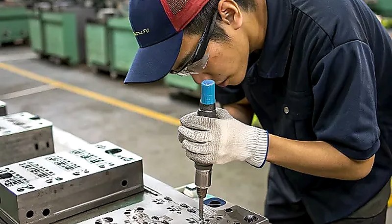
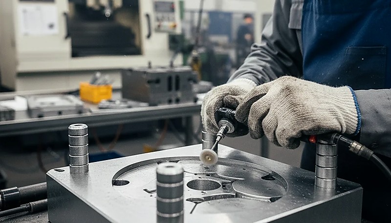
The cavity surface finish directly determines the part surface finish. SPI finishing standards range from A-1 (mirror polish, #3 diamond buff) down to D-3 (dry blast, 240-grit stone). Optical lens molds may require surface roughness below Ra 0.01 μm, while structural parts typically need only an SPI B-2 (320-grit paper) finish. Polishing is manual work done by skilled craftsmen — it is time-intensive and represents a significant portion of total mold cost for high-finish applications.
Phase 4: Assembly, Testing, and T1 Sampling
All machined components are assembled into the mold base. The cooling system is pressure-tested for leaks. Guide pins, slides, lifters, and ejector pins are fitted and checked for smooth operation. Then the mold is mounted in the injection molding machine for T1 (first article) sampling. T1 sampling is a critical milestone — it is the first time molten plastic fills the actual production mold. The samples are measured against the part drawing, and any dimensional deviations are recorded for mold adjustment.
Our in-house mold shop produces 100+ mold sets per month, with full CNC, EDM, and CMM inspection capabilities — meaning we control the entire mold-making process from design to T1 sampling without relying on outside vendors.
“Mold cooling time typically accounts for 50–70% of the total injection molding cycle time.”真
In most injection molding applications, the cooling phase dominates the cycle. Optimizing cooling channel design — using conformal cooling, baffle systems, or hot-to-cold water switching — is the most effective way to reduce cycle time and per-part cost without sacrificing quality.
“A mold that produces good parts during T1 sampling will never need modification.”偽
T1 samples are produced under carefully controlled laboratory conditions. As production volumes increase, variations in material batches, machine wear, ambient temperature, and operator technique can reveal issues that were not apparent during initial sampling. Most production molds undergo 1–3 rounds of fine-tuning after T1 to optimize for real-world production conditions.
Why Does Mold Quality Determine Your Final Part Quality?
This section is about es mold quality determine your final part quality and its impact on cost, quality, timing, or sourcing risk. There is a saying in the injection molding industry: “The mold is the quality.” Processing parameters (temperature, pressure, speed, time) can be adjusted within a range, but they cannot compensate for fundamental mold design problems. If the gate is in the wrong place, no amount of pressure adjustment will eliminate the resulting weld line. If the cooling is uneven, no hold time will prevent warpage. If the ejector pins are too few or poorly placed, parts will deform during ejection regardless of how carefully you tune the machine.
Mold quality affects five critical aspects of your production outcome. Dimensional accuracy: The cavity must be cut to compensate for plastic shrinkage (typically 0.5–2.5% depending on material and part geometry), and the mold must maintain those dimensions over hundreds of thousands of cycles without wearing. 表面仕上げ: The polish on the cavity steel is the finish on your part — there is no secondary process that improves it. 一貫性: A precision mold produces part-to-part variation under 0.05 mm; a poorly built mold will drift by 0.2 mm or more as it wears. Cycle time: Efficient cooling design shaves seconds off every cycle — and at 500,000 parts, saving 2 seconds per cycle means 278 fewer machine hours.
Mold lifespan: A properly hardened and maintained production mold can run 500,000 to over 1,000,000 cycles before needing major refurbishment.
How to Choose the Right Injection Mold Manufacturer?
This section is about to choose the right injection mold manufacturer and its impact on cost, quality, timing, or sourcing risk. Choosing a mold supplier is a long-term decision — you will be working with this company for the entire production life of your product, which could span years. Here are the factors that actually matter, based on our experience working with hundreds of clients.
In-house tooling capability: A company that designs, machines, assembles, and tests molds under one roof will always deliver better results than one that outsources individual steps. When your designer, machinist, and process engineer sit in the same building, problems get solved in hours instead of weeks. Ask whether the mold shop has its own CNC centers, EDM machines, and CMM inspection equipment — or whether they subcontract these operations.
Engineering depth: The best mold shops do not just execute your design — they improve it. A strong engineering team will catch DFM issues you missed, suggest better gating schemes, and optimize cooling for your specific geometry. Ask about their simulation capabilities (MOLDFLOW is the industry standard) and the experience level of their design engineers.
材料に関する専門知識: Different plastics behave very differently in the mold. A shop that has experience with 400+ materials has seen how each resin flows, shrinks, and degrades — and they design molds accordingly. If your part uses glass-filled nylon, for example, the mold needs hardened steel (H13 minimum) in wear areas because glass fibers are extremely abrasive to standard P20 tooling.
Communication and support: For international buyers, clear English communication is not a luxury — it is a necessity. Misunderstanding a single dimensional tolerance can result in a mold that produces parts that do not fit your assembly. Look for suppliers with dedicated English-speaking project managers and engineers who understand your technical requirements without constant clarification loops.
If you are evaluating mold suppliers for your next project, our team at ZetarMold can provide a detailed mold design proposal and competitive quote — including DFM feedback, mold flow analysis, and a clear timeline from design approval to T1 sampling. Visit our injection molding sourcing guide for a complete framework on evaluating and selecting manufacturing partners.
With experience across 400+ plastic materials and certified under ISO 9001, ISO 13485, ISO 14001, and ISO 45001, our engineering team provides material-specific mold design recommendations backed by real production data.
よくある質問
How long does it take to build an injection mold?
A standard single-cavity production mold typically takes 4–6 weeks from design approval to T1 sampling. Complex multi-cavity molds with slides, lifters, or hot runner systems can take 8–12 weeks, depending on the number of side actions and the surface finish requirements. Prototype molds built from aluminum can be completed in as little as 1–3 weeks. The key factors that drive timeline are part complexity (undercuts, thin walls, tight tolerances), cavity count, and whether the mold uses a hot runner system.
射出成形金型の典型的な費用はいくらですか?
Yes — a family mold can produce multiple different parts in the same injection molding cycle, which is especially useful for product assemblies where you need several components in matched quantities. However, family molds require careful flow balancing to ensure each cavity fills completely and consistently every cycle. They work best when the individual parts have similar volume, wall thickness, and material requirements. Parts with very different geometries or sizes may be better served by separate dedicated molds to avoid quality trade-offs.
Can an injection mold produce multiple different parts?
A hot runner mold uses heated channels to keep plastic molten inside the runner system, eliminating runner waste entirely and often reducing cycle time by 1–3 seconds per shot. The trade-off is that hot runner systems add 30–50% to the initial mold construction cost and require additional maintenance compared to cold runners. A cold runner mold uses unheated channels where the runner material solidifies along with the parts and must be separated and reground. Cold runners are simpler, more affordable, and preferred for lower-volume production runs or prototyping applications.
What is the difference between a hot runner and a cold runner mold?
A hot runner mold uses heated channels to keep plastic molten inside the runner system, eliminating runner waste entirely and often reducing cycle time by 1–3 seconds per shot. The trade-off is that hot runner systems add 30–50% to the initial mold cost and require more maintenance. A cold runner mold uses unheated channels where the runner solidifies along with the parts and must be separated and reground. Cold runners are simpler, cheaper, and preferred for lower-volume production or prototyping.
射出金型は摩耗する前に何個の部品を生産できますか?
標準的な射出成形では、適切に設計された金型と安定した加工条件により、25mm以下の寸法に対して±0.05~0.10mmの公差を一貫して達成できます。最適化されたゲート設計、制御された冷却、厳密なプロセス監視を備えた精密成形では、適切に設計された部品の重要な寸法特徴に対して±0.025mmを達成できます。より大きな寸法の公差はほぼ比例的にスケールし、通常100mmを超える寸法に対して±0.1~0.3mmとなります。金型は、生産全体を通じてこれらの公差目標を一貫して確実に達成するために、材料固有の適切な収縮補償を考慮して設計する必要があります。
What tolerances can injection molding achieve?
金型流動シミュレーションは、鋼材が切削される前に、溶融プラスチックがキャビティをどのように充填するか、溶接ラインがどこに形成されるか、部品がどのように収縮・反りするかを正確に予測します。これにより、金型を製作し、T1サンプリングで問題が明らかになった後に修正するという高コストな試行錯誤アプローチが排除されます。鋼材修正には通常、1回の修正ラウンドごとに2~4週間と$2,000~$10,000+の追加コストがかかります。プロの金型工場では、1回のシミュレーション実行コストが1回の鋼材修正コストのごく一部であるため、すべての生産金型に対してシミュレーションを標準設計工程として実施しています。
金型製作前に金型流動シミュレーションが重要なのはなぜですか?
金型流動シミュレーションは、鋼材が切削される前に、溶融プラスチックがキャビティをどのように充填するか、溶接ラインがどこに形成されるか、部品がどのように収縮・反りするかを正確に予測します。これにより、金型を製作し、T1サンプリングで問題が明らかになった後に修正するという高コストな試行錯誤アプローチが排除されます。鋼材修正には通常、1回の修正ラウンドごとに2~4週間と$2,000~$10,000+の追加コストがかかります。プロの金型工場では、1回のシミュレーション実行コストが1回の鋼材修正コストのごく一部であるため、すべての生産金型に対してシミュレーションを標準工程として実施しています。
射出金型にはどのようなメンテナンスが必要ですか?
生産用金型は、部品品質を維持し、工具寿命を延ばすために、定期的なスケジュールメンテナンスが必要です。主要なメンテナンス作業には、50,000~100,000サイクルごとのキャビティ清掃と研磨による表面仕上げの回復、エジェクタピンの検査と潤滑、熱性能維持のための冷却水路のスケール除去、侵食損傷のゲート領域検査(特にガラス繊維充填材で重要)、摩耗のためのスライドおよびリフター機構の検査が含まれます。体系的な予防保全プログラムは通常、金型の耐用年数を2~3倍に延長し、高価な計画外の生産停止を防止します。
-
MOLDFLOWシミュレーション: Moldflowは、オートデスクが開発したプラスチック射出成形シミュレーションソフトウェアで、有限要素解析を用いて射出成形プロセスにおけるポリマーの流動、冷却、収縮挙動を予測します。 ↩
-
製造性のための設計(DFM): 製造性を考慮した設計(DFM)とは、肉厚の均一性、抜き勾配、リブの比率、アンダーカットの最小化などの要素を考慮して、部品を容易かつ費用効果的に製造できるように設計する実践を指し、成功した射出成形を確保します。 ↩
-
放電加工(EDM): 放電加工(EDM)は、電極とワークピースの間で制御された電気火花を用いて材料を除去する精密加工プロセスであり、従来の切削工具では達成できない硬化鋼材の複雑な形状を加工することが可能です。 ↩



 EN
EN  ES
ES  FR
FR  DE
DE  PT
PT  AR
AR  RU
RU  JA
JA  KO
KO  IT
IT  NL
NL  TR
TR  PL
PL 